Your 2025 Guide to Series and Parallel Resistors
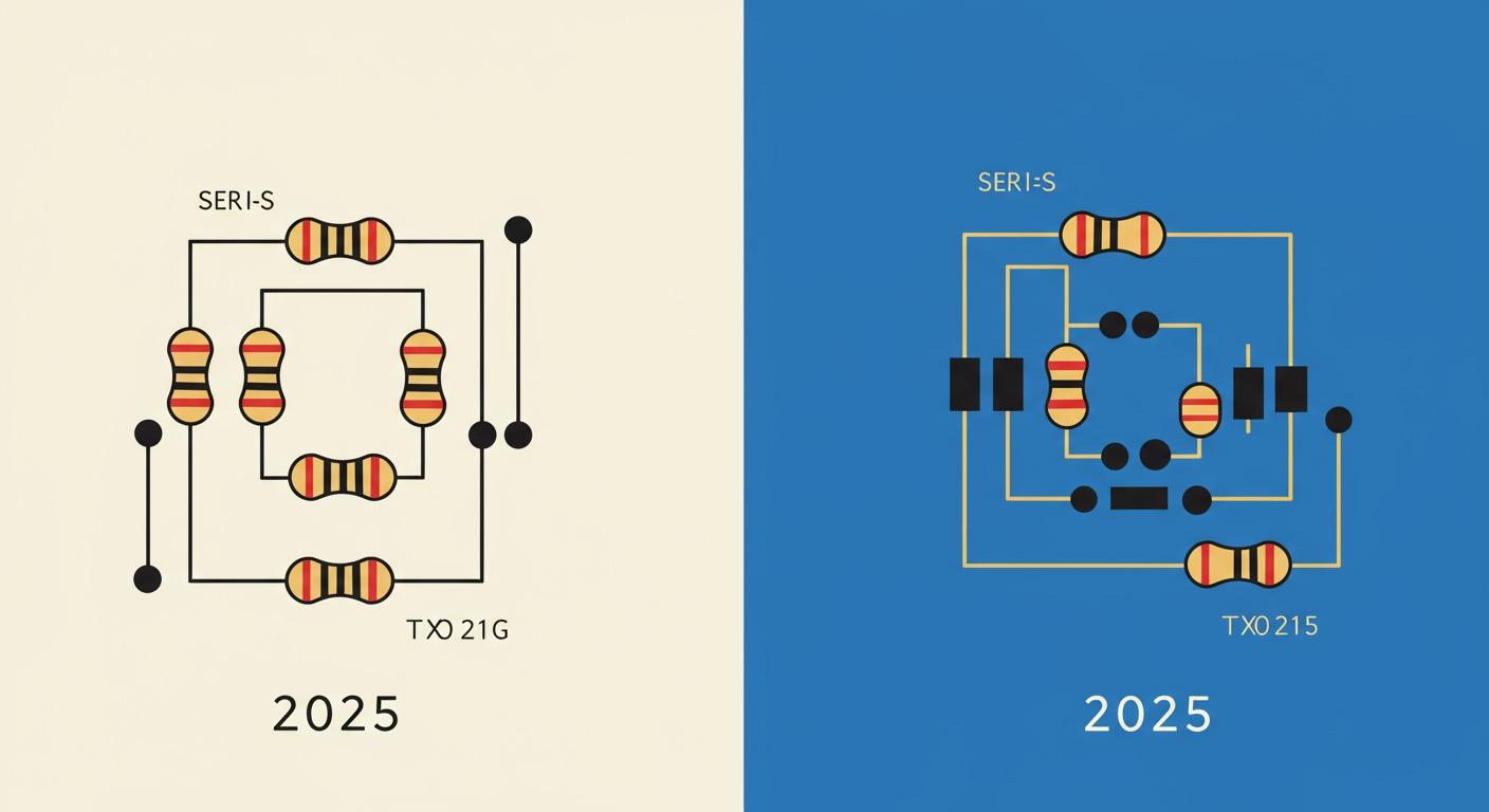
Connecting a resistor end-to-end versus side-by-side creates different outcomes in your projects. You join a growing community of hobbyists. This group drives a booming market for resistor kits. Understanding resistors in series and parallel is a core skill for any electronics enthusiast. Your circuit design depends on choosing the right resistor. Each resistor placement affects the entire circuit.
Have you ever wondered why adding another resistor to your circuit can dim an LED? 💡
This guide will empower you to make the right design choices for every project.
Key Takeaways
- Series circuits have one path for current. All components are in a line.
- Parallel circuits have multiple paths for current. Components are side-by-side.
- Total resistance increases in series circuits. It decreases in parallel circuits.
- Voltage divides in series circuits. Voltage stays the same across parallel branches.
- A single failure stops a series circuit. Other parts work if one fails in a parallel circuit.
- Use series for voltage dividers or current limiting. Use parallel for shared voltage or redundancy.
- Ohm's Law (V = IR) explains how voltage, current, and resistance relate.
- You can combine series and parallel parts to solve complex circuits.
Understanding Resistors in Series and Parallel
Before you can master circuit design, you need to understand the two basic ways to connect components. The concepts of resistors in series and parallel form the foundation of electronics. Each configuration changes how your circuit behaves. Let's explore what makes them different.
What is a Series Circuit?
A series circuit provides a single, continuous path for electrical current. Imagine all the components are arranged sequentially, like beads on a string. The current flows through the first resistor, then the second, and so on, without any alternative routes.
You can think of it like water flowing in a single river. All the water must pass through every part of the riverbed to reach the ocean. In the same way, all the electricity in a series circuit must pass through every resistor.
Key characteristics of a series circuit include:
- The current is the same at every point in the circuit.
- The total voltage is the sum of the voltages across each component.
- The total resistance is the sum of every individual resistor.
What is a Parallel Circuit?
A parallel circuit offers multiple paths for the current to flow. You create this when you connect two or more components side-by-side. Their "heads" are all joined at one common point, and their "tails" are all joined at another. This setup splits the main current, allowing a portion of it to travel through each separate branch of the circuit. Different resistor types can be mixed in these configurations.
How Do Resistors Work in a Circuit?
You might wonder, how do resistors work to control this flow? A resistor acts like a bottleneck in a pipe. It impedes the flow of electrons. As electrons push through the resistive material, they collide with atoms. This process converts electrical energy into heat, slowing the current down.
This relationship is perfectly described by a fundamental rule called Ohm's Law (V = IR). It connects voltage (V), current (I), and resistance (R).
- Voltage (V) is the "push" or pressure driving the electrons.
- Current (I) is the "flow" or rate of electrons passing a point.
- Resistance (R) is the opposition to that flow.
A resistor with a higher value provides more opposition, which reduces the current for a given voltage. Understanding the different types of resistors and how they function is crucial for building effective electronics. This knowledge of resistors in series and parallel is your first step toward designing more complex projects.
Analyzing a Series Circuit
You can master your projects by understanding how a series circuit behaves. This configuration is fundamental, and its properties are predictable and easy to calculate. Let's break down its characteristics so you can use it effectively.
Core Characteristics
Every series circuit shares three defining traits. These traits dictate how current, voltage, and resistance interact within the circuit.
Single Current Path
In a series circuit, you provide only one path for the electricity. The current flows through each component one after another. Imagine a single-lane road; every car must follow the same route. Similarly, the amount of current is identical at every point in the circuit. If you measure the current before the first resistor and after the last one, the value will be the same.
Voltage Division
The total voltage supplied by your power source is shared among all the components. Each resistor "drops" or uses a portion of the total voltage. The amount of voltage each resistor drops depends on its resistance value. A resistor with a higher resistance will use a larger share of the voltage. This property makes the series circuit a natural voltage divider.
Resistance Summation
The total opposition to the current, or total resistance, is the sum of all individual resistances. Each resistor adds its own resistance to the total. This means the total resistance in a series circuit will always be greater than the value of any single resistor in it.
The Total Resistance Formula
Calculating resistance in a series circuit is straightforward. You just need one simple formula.
The R_total Equation
You can find the total resistance (R_total) by adding the values of each resistor. The formula is:
R_total = R₁ + R₂ + R₃ + ... + Rₙ
Here, R₁, R₂, and R₃ represent the resistance of the first, second, and third resistor, and so on.
Rationale for Simple Addition
You might ask why you can just add the resistance values together. The reason comes from Ohm's Law and the conservation of energy. The total voltage in the circuit is the sum of the voltage drops across each individual resistor.
This simple addition works because the same current flows through every component. Let's walk through the logic:
- The total voltage (V_total) equals the sum of each voltage drop:
V_total = V₁ + V₂ + V₃ + ... - You can express each voltage drop using Ohm's Law (V = IR):
V₁ = I × R₁,V₂ = I × R₂, etc. - Substitute these into the first equation:
V_total = (I × R₁) + (I × R₂) + (I × R₃) + ... - You can factor out the common current (I):
V_total = I × (R₁ + R₂ + R₃ + ...) - Since total resistance is
R_total = V_total / I, you can see thatR_totalmust equalR₁ + R₂ + R₃ + ...
This proves that each resistor contributes its full resistance to the circuit's total opposition.
Calculation Example
Let's apply this to a real-world scenario. Imagine you have a circuit with two resistors connected in series.
- Resistor 1 (R₁) has a value of 100 Ω.
- Resistor 2 (R₂) has a value of 220 Ω.
Your task is calculating resistance for the entire circuit.
Step-by-Step Calculation:
State the formula:
R_total = R₁ + R₂Substitute the values:
R_total = 100 Ω + 220 ΩCalculate the result:
R_total = 320 Ω
The total resistance of your series circuit is 320 Ω. This higher resistance will limit the overall current more than either resistor would alone.
Analyzing a Parallel Circuit
You can unlock more advanced designs by understanding the parallel circuit. This configuration behaves very differently from a series circuit. It opens up new possibilities for controlling current and voltage in your projects. Let's dive into its unique properties.
Core Characteristics
A parallel circuit has three distinct traits that define its function. You will use these characteristics to create more versatile electronics.
Multiple Current Paths
You create a parallel circuit by giving the current more than one path to follow. Think of a highway splitting into multiple lanes. The total traffic (current) divides, with some cars flowing through each lane. In your circuit, the main current from the power source splits at a junction. A portion of the current travels through each separate branch containing a resistor. The current then recombines after passing through the branches.
Constant Voltage
The voltage across each parallel branch is the same. Every branch connects to the same two points in the circuit. Therefore, each resistor in a parallel setup receives the full voltage from your power source. If you supply 9V to a parallel circuit, every resistor in that circuit will have a 9V potential difference across it. This constant voltage is a key feature.
Decreased Total Resistance
Adding a resistor in parallel decreases the total resistance of the circuit. This might seem strange at first. You are adding more components, yet the opposition to the current goes down. This happens because you are providing more pathways for the current to flow. Each new path makes it easier for the overall current to move through the circuit.
Key Takeaway: The total resistance in a parallel circuit will always be less than the value of the smallest individual resistor.
The Total Resistance Formula
Calculating the total resistance for a parallel circuit requires a different approach than a series circuit. You have two main formulas to use.
The Reciprocal Equation
You find the total resistance (R_total) using the reciprocals of each resistor value. The general formula is:
1 / R_total = 1 / R₁ + 1 / R₂ + 1 / R₃ + ... + 1 / Rₙ
To get the final resistance, you first add up all the 1/R terms. Then, you take the reciprocal of that sum.
The Product-Over-Sum Rule
You can use a handy shortcut when your circuit has only two parallel resistors. This is called the product-over-sum rule. It simplifies the calculation significantly.
R_total = (R₁ * R₂) / (R₁ + R₂)
This rule is a direct mathematical simplification of the general reciprocal equation for a two-resistor scenario. Here is how you derive it:
- You start with the reciprocal formula for two resistors:
1 / R_total = 1 / R₁ + 1 / R₂ - You find a common denominator for the right side:
1 / R_total = (R₂ / (R₁ * R₂)) + (R₁ / (R₁ * R₂)) - You combine the fractions:
1 / R_total = (R₁ + R₂) / (R₁ * R₂) - Finally, you flip both sides to solve for
R_total, which gives you the product over the sum:R_total = (R₁ * R₂) / (R₁ + R₂)
Calculation Example
Let's see these formulas in action. Imagine a circuit with two resistors connected in parallel.
- Resistor 1 (R₁) has a value of 1kΩ (1000 Ω).
- Resistor 2 (R₂) has a value of 2kΩ (2000 Ω).
Your goal is to find the total resistance of this parallel arrangement.
Method 1: The Reciprocal Equation
State the formula:
1 / R_total = 1 / R₁ + 1 / R₂Substitute the values:
1 / R_total = 1 / 1000 Ω + 1 / 2000 Ω1 / R_total = 0.001 + 0.00051 / R_total = 0.0015Solve for R_total (take the reciprocal):
R_total = 1 / 0.0015 ≈ 667 Ω
Method 2: The Product-Over-Sum Rule
State the formula:
R_total = (R₁ * R₂) / (R₁ + R₂)Substitute the values:
R_total = (1000 * 2000) / (1000 + 2000)R_total = 2,000,000 / 3000Calculate the result:
R_total ≈ 667 Ω
Both methods give you the same total resistance. Notice that 667 Ω is less than the smallest resistor value of 1000 Ω. This confirms that adding the 2kΩ resistor in parallel provided an extra path for the current, reducing the overall resistance of the circuit and allowing more total current for a given voltage.
Series vs. Parallel: A Direct Comparison

You now understand the individual characteristics of series and parallel circuits. Let's place them side-by-side to highlight their key differences. This direct comparison will help you decide which configuration to use for your specific project goals. Understanding the behavior of resistors in series and parallel is crucial for effective circuit design.
Current Flow
The path of the electrical current is the most fundamental difference.
- In a Series Circuit: You create a single lane for the current. The electricity must flow through the first resistor, then the second, and so on. The amount of current is the same at every point in this circuit.
- In a Parallel Circuit: You provide multiple lanes for the current. The main current from your power source splits, and a portion of it travels through each parallel branch. The current in each branch can be different, depending on the resistance in that path.
Voltage Behavior
The way your circuit handles voltage changes dramatically between the two setups. This behavior is explained by a rule called Kirchhoff's Voltage Law.
In a series circuit, the total voltage from your power source is divided among the components. Each resistor "uses up" a portion of the voltage. The sum of these individual voltage drops equals the total source voltage. A resistor with higher resistance will claim a larger share of the voltage.
In a parallel circuit, the opposite is true.
The voltage across every parallel branch is constant and equal. Each resistor connects to the same two points in the circuit, so each one receives the full source voltage. If you supply 9V to the circuit, every parallel resistor gets 9V. No voltage division occurs.
Total Resistance Impact
Your choice of circuit configuration directly controls the total resistance.
- Series Increases Resistance: When you add a resistor in series, you increase the total resistance of the circuit. The total resistance is always greater than your largest individual resistor's resistance. Each component adds its full resistance to the total opposition.
- Parallel Decreases Resistance: When you add a resistor in parallel, you decrease the total resistance. This happens because you are adding another path for the current to flow. This makes it easier for electricity to move through the entire circuit. The total resistance will always be less than your smallest individual resistor's resistance. This lower overall resistance allows more total current to flow for a given voltage.
Circuit Behavior on Failure
You must consider what happens when a component fails. The way your circuit responds to a broken resistor depends entirely on whether you used a series or parallel design. This is a critical factor for building reliable and robust projects.
In a series circuit, a single failure is catastrophic.
- Imagine one resistor burns out and creates an open gap. The single path for the current is now broken.
- This stops the flow of electricity completely. The entire circuit ceases to function.
- You can think of old-fashioned holiday lights. When one bulb went out, the whole string went dark. The total resistance of the circuit effectively becomes infinite.
A parallel circuit offers much greater resilience.
If one resistor fails by becoming an open circuit, the other branches are not affected. The remaining resistors will continue to conduct current. This ensures your circuit remains at least partially operational.
The voltage across the other parallel branches remains unchanged because they are still connected directly to the power source. Since their individual resistance values have not changed, their branch currents also stay the same. The main impact is on the total resistance and total current of the circuit. With one less path available, the total resistance of the circuit increases, which in turn decreases the total current drawn from the source. The failure of a single resistor does not shut down the entire system. This inherent redundancy is a major advantage of a parallel circuit. The change in total resistance is a key diagnostic clue.
To help you choose the right setup, here is a summary table that contrasts the two configurations.
| Feature | Series Circuit | Parallel Circuit |
|---|---|---|
| Current | Stays the same through each component. | Splits among the different branches. |
| Voltage | Divides among the components. | Stays the same across each branch. |
| Total Resistance | R_total = R₁ + R₂ + ... (Increases) | 1/R_total = 1/R₁ + 1/R₂ + ... (Decreases) |
| Failure Impact | If one part fails open, the entire circuit stops working. | If one branch fails open, the other branches continue to work. |
This table provides a quick reference for the fundamental differences in resistance, current, and overall behavior. Understanding these distinctions in resistance and circuit integrity is essential for your designs.
Practical Use of Resistors in Circuits
You can now move from theory to practice. Understanding the practical applications of resistors will transform your projects. Your choice between series and parallel configurations depends entirely on what you want your circuit to accomplish. Let's explore common scenarios for each setup.
Common Series Applications
You will use a series circuit when you need to increase total resistance or divide voltage. This configuration is essential for controlling and protecting components.
Voltage Dividers
You can use a series circuit to create a voltage divider. This circuit taps into the voltage between two resistors to produce a lower output voltage. This is a fundamental technique in circuit design. You can find voltage dividers in many devices.
- Reading Sensors: You can use a voltage divider to measure resistance changes from sensors like photoresistors or thermistors. Your microcontroller reads the output voltage to determine light or temperature levels.
- Adjusting Signal Levels: You can scale down a 5V signal to a 3.3V level. This allows components with different voltage requirements to communicate.
- Creating Controls: You use a potentiometer, which is a variable resistor, as an adjustable voltage divider. This is how volume knobs on stereos and control knobs on other electronics work.
Current Limiting for LEDs
You must protect components like LEDs from receiving too much current. An LED has very little internal resistance, so you need to add a resistor in series to limit the current flow. Without this protection, the LED will burn out instantly.
You can calculate the correct resistor value with a simple formula. This ensures your LED gets the right amount of current.
Resistor = (Source Voltage – LED Voltage) / Desired LED Current
To find the right resistance, you follow these steps:
- Find your power source's voltage (e.g., 9V battery).
- Find your LED's forward voltage and desired current from its datasheet (e.g., 2V and 20mA).
- Apply the formula to calculate the necessary resistance.
Increasing Resistance Values
Sometimes, your circuit design requires a specific resistance value that you do not have. You can achieve a higher total resistance by connecting multiple resistors in series. The total resistance is simply the sum of the individual values.
Common Parallel Applications
You will use a parallel circuit when you need to decrease total resistance or supply the same voltage to multiple components. These are some of the most useful practical applications of resistors.
Ensuring Circuit Redundancy
A parallel circuit offers reliability. If one component in a branch fails (breaks open), the other parallel branches continue to function. The overall circuit remains operational, which is critical for building robust systems.
Decreasing Resistance Values
You may need a resistance value that is not a standard component value. You can create a smaller, custom resistance by placing a resistor in parallel with another. For example, if you need a 90Ω resistance but only have a 100Ω resistor, you can place a 910Ω resistor in parallel with it to get a total resistance of about 90.099Ω. This technique gives you great flexibility.
Supplying a Shared Voltage
A parallel configuration delivers the same voltage to every branch. This is essential when you need multiple components to receive the full source voltage. Your home's electrical wiring is a perfect example. All outlets in a room are wired in parallel, ensuring every appliance you plug in receives the same 120 volts. This is one of the most important uses of resistors in circuits.
Advanced Circuit Analysis Techniques
You are now ready to tackle more complex circuits. Your skills in series and parallel configurations are the building blocks for advanced analysis. These techniques will help you solve almost any resistor network you encounter.
Reading Resistor Circuit Diagrams
You first need to learn the language of electronics: schematic diagrams. These drawings use standard symbols to represent components. Understanding these symbols is the first step to analyzing resistor circuit diagrams.
You will also see other important symbols:
- Power Supply: A series of alternating long and short lines often shows a battery or DC voltage source.
- Ground (0V): This is your circuit's reference point. It is usually drawn as three descending horizontal lines.
Learning these symbols helps you visualize how a circuit is connected.
Solving Combination Circuits
Many circuits are not purely series or parallel. They are "combination" circuits that mix both types. You can solve them by breaking the problem down into smaller steps.
To find the total resistance of a combination circuit, you can follow this method:
- Identify the parallel sections. Look for branches where the current splits.
- Simplify each parallel section. Calculate the equivalent resistance for each parallel group. This turns each group into a single conceptual resistor.
- Redraw the circuit. After simplifying, your complex circuit becomes a simple series circuit.
- Calculate the final resistance. Add up all the series resistances to find the total for the entire circuit.
This systematic approach transforms a confusing layout into a simple problem. It is the key to mastering complex resistor circuit diagrams.
Introduction to Nodal Analysis
For very complex circuits, you may need a more powerful tool. Nodal analysis is a universal technique that can solve almost any circuit. It works by focusing on the "nodes" in a circuit. A node is any point where two or more components connect.
You apply this law at each main node to create a set of equations. Solving these equations gives you the voltage at each node. This method is very effective for circuits with multiple power sources. It simplifies the math needed for complicated resistor circuit diagrams.
Introduction to Mesh Analysis
You can use another powerful method called mesh analysis for certain circuits. This technique is especially useful for "planar" circuits. A planar circuit is one you can draw on a flat surface without any wires crossing over each other. This method helps you make sense of complex resistor circuit diagrams with multiple power sources.
Mesh analysis uses Kirchhoff's Voltage Law (KVL). KVL states that the sum of all voltages around any closed loop in a circuit must equal zero. You apply this law to each "mesh" or loop in your circuit to create a set of equations.
Solving these equations helps you find the current in each loop. These loop currents then combine to give you the actual current flowing through any component. This technique is very efficient when your circuit has many voltage sources or fewer loops than nodes. It simplifies the process of analyzing otherwise confusing resistor circuit diagrams. However, you cannot use this method for non-planar circuits, where wires must cross.
Simplifying with Norton's Theorem
Sometimes, you only care about the behavior of one part of a large circuit. Norton's theorem lets you simplify the rest of the circuit into a much easier model. This theorem helps you replace a complex network of sources and resistors with a simple equivalent. The equivalent circuit contains a single current source in parallel with a single resistor. This makes analyzing resistor circuit diagrams much faster.
This simplified model is called a Norton equivalent circuit. It consists of:
- A Norton Current Source (I_N): This represents the total current the original circuit can deliver.
- A Norton Resistance (R_N): This represents the internal resistance of the original circuit.
You can find these values by following a few steps:
- First, you identify the component you want to analyze (the "load") and temporarily remove it.
- You then create a short circuit where the load was and calculate the current flowing through it. This value is your Norton Current (I_N).
- Next, you turn off all independent power sources in the original circuit. You replace voltage sources with short circuits and current sources with open circuits.
- You calculate the total resistance looking back into the terminals where the load was. This value is your Norton Resistance (R_N).
Once you have I_N and R_N, you can draw your simplified circuit. You just connect your original load to this new equivalent circuit to easily calculate its voltage and current.
You now understand the core concepts of resistors in series and parallel. Series circuits add resistance and divide the total voltage. Parallel circuits decrease resistance and keep the voltage the same across each branch. This knowledge is your guide for effective circuit design. You can now build better electrical circuits.
You have the skills to analyze and design your own electrical circuits. Go create something amazing! 🚀
FAQ
Why does total resistance decrease in a parallel circuit?
You give the current more paths to travel. Think of opening more checkout lanes at a store. More lanes make it easier for shoppers (current) to get through. This lowers the overall opposition, or resistance, of the entire system.
What happens if I use resistors with different values in parallel?
The voltage across each resistor stays the same. The current, however, will split. The path with the lower resistance will get more current. The path with the higher resistance will get less current. This is a key principle of parallel circuits.
Can I mix series and parallel connections in one circuit?
Yes, you absolutely can. You create a "combination circuit" by mixing them. Many electronic devices use combination circuits. You solve them by simplifying the parallel parts into single resistors first, then adding up the series parts.
Which is better for wiring multiple LEDs?
For most projects, you should wire LEDs in parallel. Each LED gets its own current-limiting resistor in its branch. This ensures every LED receives the correct voltage and current. It also keeps the other LEDs lit if one burns out.
How do I find a short circuit in my project?
A short circuit creates a very low-resistance path. This causes a large amount of current to flow. You can use a multimeter in continuity mode to test for shorts. A continuous beep between two points indicates a direct connection.
Why do modern holiday lights stay on if one bulb fails? 🎄
Modern holiday lights connect the bulbs in parallel. Each bulb is its own branch. If one bulb burns out, it only breaks its own path. The other parallel branches remain complete, so the rest of the lights stay lit.