A Simple Look at Diodes in Electronics
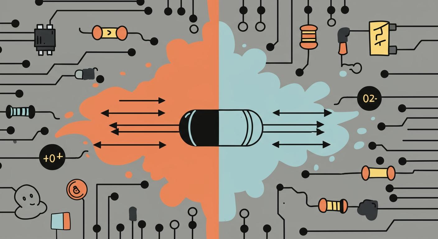
So, what is a diode? You can see a diode as a fundamental one-way switch for electric current. Karl Ferdinand Braun first observed this effect in 1874, creating the first semiconductor diode. This simple function is the core of the diodes meaning.
A diode acts like a one-way street for electricity 🚦. It allows current to travel in one direction but blocks it from going the other way.
Every diode has two terminals: an anode and a cathode. You can easily find the cathode on a physical diode by looking for the stripe. This tiny component is a big deal; the global diode market is estimated to reach over $18 billion by 2025.
Key Takeaways
- A diode acts like a one-way street for electricity. It lets current flow in one direction but stops it from going the other way.
- Diodes work because of a special P-N junction inside them. This junction controls when electricity can pass through.
- You can turn a diode 'on' by connecting it in 'forward bias.' This lets current flow. Connecting it backward, in 'reverse bias,' turns it 'off' and blocks current.
- Different types of diodes do different jobs. For example, LEDs make light, and Zener diodes help keep voltage steady.
- Always check the diode's symbol and stripe to connect it correctly in your circuit. A wrong connection can stop your project from working.
The Diodes Meaning and Function
To truly understand the diodes meaning, you need to look inside. A diode is a semiconductor device, usually made of silicon. The magic happens at its P-N junction, which is the core of the theory of diode operation. Here’s how it’s made:
- Pure silicon is "doped" or mixed with specific impurities to change its properties.
- N-type silicon is created by adding elements like phosphorus. This gives the silicon an excess of free negative charge carriers (electrons).
- P-type silicon is created by adding elements like boron. This creates an excess of positive charge carriers (called "holes").
- When these two materials meet, electrons from the N-side rush to fill the holes on the P-side. This creates a thin barrier at the junction called the depletion region, which is empty of free charge carriers. This region establishes a small electric field, creating a built-in voltage of about 0.7 volts for silicon.
This simple P-N junction is how diodes work, allowing it to control the flow of current. The direction of the voltage connected to the diode determines whether it's "on" or "off."
Forward Bias: Letting Current Pass
You turn a diode "on" by connecting it in forward bias. This means you connect the positive terminal of your power source to the anode (P-side) and the negative terminal to the cathode (N-side).
When you apply a voltage this way, it pushes the electrons and holes toward the P-N junction. This action shrinks the depletion region. Once the voltage connected to the diode overcomes the small built-in voltage (about 0.7V for a standard silicon diode), the barrier is broken. Current can now flow easily from the anode to the cathode.
The current-voltage relationship in a forward-biased diode is exponential. After hitting the threshold voltage, even a tiny increase in voltage causes a large increase in current. This is described by the Shockley diode equation:
I = I_S * (e^(V_D / (n * V_T)) - 1)
This small voltage requirement is known as the forward voltage drop. It's the "price" you pay in voltage to turn the diode on.
Pro Tip 💡: The forward voltage of a diode changes with temperature. For most silicon diodes, the voltage drop decreases as the temperature rises. This property is so reliable that you can even use a diode as a simple temperature sensor!
Reverse Bias: Blocking Current
Now, what happens if you flip the connections? When you connect the positive terminal of your power source to the cathode (N-side) and the negative terminal to the anode (P-side), the diode is in reverse bias.
In this state, the external voltage pulls the electrons and holes away from the P-N junction. This causes the depletion region to become wider, strengthening the barrier. The wider barrier effectively blocks the main current from flowing. The diode acts like an open switch, and your circuit is "off."
However, no diode is perfect. A tiny amount of current, called reverse leakage current, still manages to sneak through. This current is usually extremely small (in the microamps or nanoamps range) and is caused by minority charge carriers.
One of the most important diode properties is its Peak Inverse Voltage (PIV).
Warning! ⚠️ The Peak Inverse Voltage (PIV) is the maximum reverse voltage a diode can handle before it breaks down. If the voltage you apply exceeds the PIV rating, the diode will fail and may be permanently damaged, potentially harming other components in your circuit. Always choose a diode with a PIV rating higher than any voltage it will face in your application.
If the PIV is exceeded, the diode enters a breakdown state. The two common types of breakdown are:
| Feature | Avalanche Breakdown | Zener Breakdown |
|---|---|---|
| Doping | Lightly doped diode | Heavily doped diode |
| Mechanism | High voltage accelerates electrons, causing them to crash into atoms and create more free electrons. | A strong electric field pulls electrons directly from their atoms. |
| Voltage | Occurs at higher voltages (typically >5V) | Occurs at lower voltages (typically <5V) |
Understanding this two-sided behavior—conducting in forward bias and blocking in reverse bias—is the key to grasping the diodes meaning and its role in electronics.
Common Types of Diode
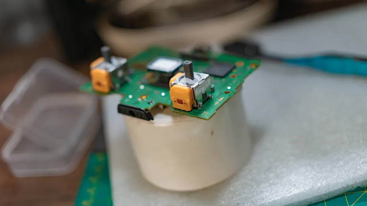
The basic one-way function is the foundation for all diodes. However, engineers have created different types of diodes optimized for specific tasks. You can think of them as specialized tools in your electronics toolkit. Understanding these common types unlocks a new level of circuit design possibilities.
Rectifier Diodes
You will most often encounter rectifier diodes in power supplies. Their main job is to convert alternating current (AC), which constantly changes direction, into direct current (DC), which flows in only one direction. This process is called rectification. These rectifiers act as one-way routes for electricity.
A very common circuit for this is the full-bridge rectifier. It uses four diodes to steer the current. Here is how you can visualize its operation:
- Arrangement: Four diodes are set up in a diamond or bridge shape.
- Positive AC Half-Cycle: During the first half of the AC wave, two of the diodes turn on (become forward-biased). They allow current to flow through the load (the part of the circuit doing the work). The other two diodes block the current.
- Negative AC Half-Cycle: When the AC wave flips, the roles reverse. The other two diodes now turn on and conduct current, while the first pair blocks it.
- Unidirectional Flow: This clever switching ensures the current always travels through the load in the same direction. You get a pulsating DC output from an AC input.
A popular family of rectifier diodes is the 1N400x series. The 1N4004 is a great general-purpose diode. You can see its typical ratings below.
| Characteristic | Rating |
|---|---|
| Maximum Reverse Voltage | 400 volts |
| Maximum Average Current | 1.0 amp |
| Peak Forward Surge Current | 30 amps |
| Maximum Forward Voltage | 1.1 volts |
Not all rectifiers are the same. You must choose based on the circuit's frequency.
| Feature | Fast Recovery Rectifier Diodes | Standard Rectifier Diodes |
|---|---|---|
| Best For | High-frequency circuits (e.g., switch-mode power supplies) | Low-frequency circuits (e.g., mains power 50/60Hz) |
| Switching Speed | Very fast (nanoseconds) | Slower |
| Use Case | Inverters, motor drives | Simple power supplies, battery chargers |
Light-Emitting Diodes (LEDs)
You are likely familiar with light-emitting diodes, or the LED. An LED is a special type of diode that does something amazing: it converts electrical energy directly into light. When you forward-bias an LED, electrons and holes recombine at the P-N junction. This recombination releases energy in the form of photons, which are particles of light.
The color of light an LED produces is not random. It is determined by the semiconductor material's energy band gap.
The band gap is like a fixed-height step. When an electron "hops" down this step, it releases a specific, consistent amount of energy. This energy corresponds to a specific wavelength, or color, of light.
Different materials create different colors. You can see some examples here:
- Red Light: Gallium Arsenide Phosphide (GaAsP)
- Green Light: Gallium Nitride (GaN) or Gallium Phosphide (GaP)
- Blue Light: Gallium Nitride (GaN) or Silicon Carbide (SiC)
The applications for light-emitting diodes go far beyond simple indicator lights. Many LED types emit light outside the visible spectrum, leading to important industrial and consumer applications.
| Wavelength Range | LED Type | Common Applications |
|---|---|---|
| 200–280 nm (UV-C) | Ultraviolet LED | Water purification, air and surface sterilization |
| 315–400 nm (UV-A) | Ultraviolet LED | Curing industrial inks and adhesives, counterfeit currency detection |
| 850–940 nm (Infrared) | Infrared LED | TV remote controls, night-vision cameras, security systems |
Zener Diodes
While most diodes are designed to block current in reverse bias, Zener diodes are special. You use them specifically for their ability to conduct current backward at a precise voltage. This makes them perfect for voltage regulation.
The most important property of a Zener diode is its Zener Voltage (Vz).
You can use this unique feature to build a simple voltage regulator. You connect the Zener diode in reverse bias, parallel to your load. A series resistor is placed between the power source and the Zener. This resistor limits the total current. The Zener diode then maintains a steady voltage output, protecting your circuit from fluctuations in the input supply. If the input voltage rises, the Zener simply draws more current to keep the output voltage stable at Vz.
When you select Zener diodes, you must also consider their power rating. This rating tells you how much power the Zener can handle without overheating. You can calculate the minimum power rating your Zener needs with a simple formula:
Power = Zener Voltage * Maximum Current
Choosing a Zener with a power rating that is too low for your circuit will cause it to fail. Common Zener diodes are available with ratings like 0.5W and 1W.
Schottky Diodes
When you need speed and efficiency, you turn to Schottky diodes. A Schottky diode is known for two main advantages: a very low forward voltage drop (typically 0.15V to 0.45V) and extremely fast switching speed. This makes the Schottky diode a star player in high-frequency and low-voltage applications.
The secret to the Schottky diode's performance is its unique structure. Unlike other types, it does not have a P-N junction. Instead, it uses a metal-semiconductor junction. This design difference is key.
| Diode Type | Junction Structure | Doping Level |
|---|---|---|
| Rectifier Diode | P-N junction | Normal |
| Zener Diode | P-N junction | Heavily doped |
| Schottky Diode | Metal-semiconductor junction | N/A (unipolar device) |
Because there are no minority charge carriers to clean out of the junction when it switches, a Schottky can turn on and off almost instantly. This rapid response is essential for modern electronics. The fast switching of Schottky diodes makes them perfect for one of the most common typical diode applications: switch-mode power supplies (SMPS). In an SMPS, the Schottky acts as a rectifier, converting AC to DC with very little energy lost as heat. This high efficiency is vital for creating compact and cool-running power supplies for computers and other devices.
The Diode Schematic Symbol
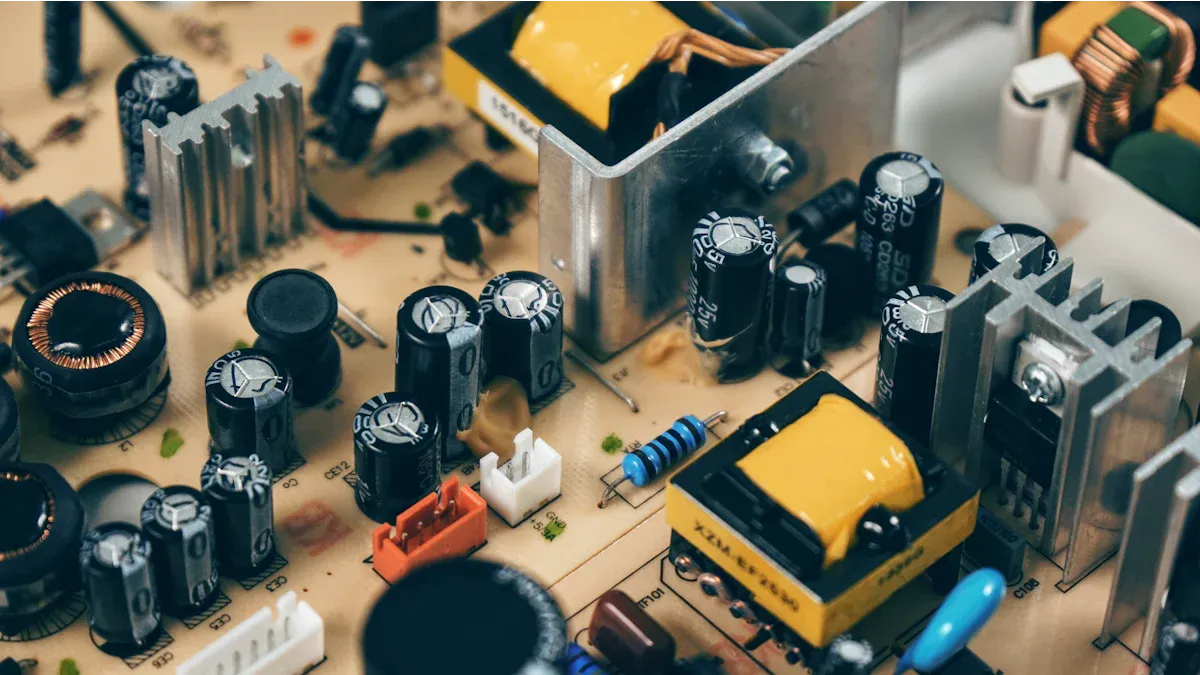
When you read a circuit diagram, you will see symbols instead of pictures of components. The schematic symbol for a diode is simple and tells you everything you need to know about its orientation. This universal symbol helps engineers everywhere read and understand circuits.
International standards help ensure these symbols are consistent. Key standards include:
- IEC 60617: An international standard for graphical symbols.
- IEEE 315: A standard widely used in North America for many years.
These standards create a uniform visual language for electronics, so a diode symbol looks the same on diagrams around the world.
The Triangle and Line
The standard diode symbol consists of two parts: a triangle and a line. Each part has a specific meaning.
The triangle represents the anode and points in the direction of conventional current flow. Think of it as an arrow showing the "one-way street" for electricity. The current flows from the positive side to the negative side. The flat line at the tip of the triangle represents the cathode. This line acts as a barrier, visually showing how the diode blocks current from flowing in the reverse direction. A higher voltage on the anode side allows current to pass through the diode.
Matching Symbol to Component
You must correctly match the schematic symbol to the physical diode. Placing a diode backward will block current and prevent your circuit from working. It can even cause the diode to overheat and fail if the reverse voltage is too high.
Here is how you can match the symbol to the component 💡:
- The Stripe: Most physical diodes have a colored band or stripe on one end. This stripe marks the cathode. It corresponds to the flat line in the schematic symbol.
- The Arrow: The body of the diode without the stripe is the anode. This corresponds to the base of the triangle in the symbol.
When you place a diode on a printed circuit board (PCB), you can also look for markings on the board itself. The PCB silkscreen often shows the diode symbol (triangle and line) or uses a + sign for the anode and a - sign for the cathode. Always double-check the orientation to ensure the current can flow correctly and the diode functions as intended. A wrong connection stops the flow of current and can damage your project.
You now understand the core diodes meaning. A diode is a fundamental one-way gate for electric current. You connect a diode correctly in forward bias to let current pass. Connecting the diode backward in reverse bias stops the current. This simple diode is a key building block. Understanding this diode unlocks countless circuits. You can see how a rectifier diode and a Zener diode work together in a phone charger to provide stable power. This knowledge helps you understand how your everyday electronics function.
FAQ
What happens if I put a diode in backward?
You connect the diode in reverse bias. It acts like an open switch and blocks most current. Your circuit will likely not work as intended. Applying too much reverse voltage can permanently damage the diode and other components.
Can I use any diode for my project?
You must choose the right diode for the job. Consider the maximum current and reverse voltage your circuit uses. For high-frequency circuits, you need a fast-switching diode like a Schottky. Always check the component's datasheet.
Why do LEDs need a resistor?
An LED has very little internal resistance. You must add a series resistor to limit the current flowing through it. Without a resistor, the LED will draw too much current from the power source and burn out quickly.
What is the difference between a diode and a resistor?
A resistor and a diode both affect current, but they function differently.
A resistor limits current flow equally in both directions. A diode allows current to flow easily in one direction and blocks it in the other, acting like a one-way valve.