Mastering Oscilloscope Basics for Beginners
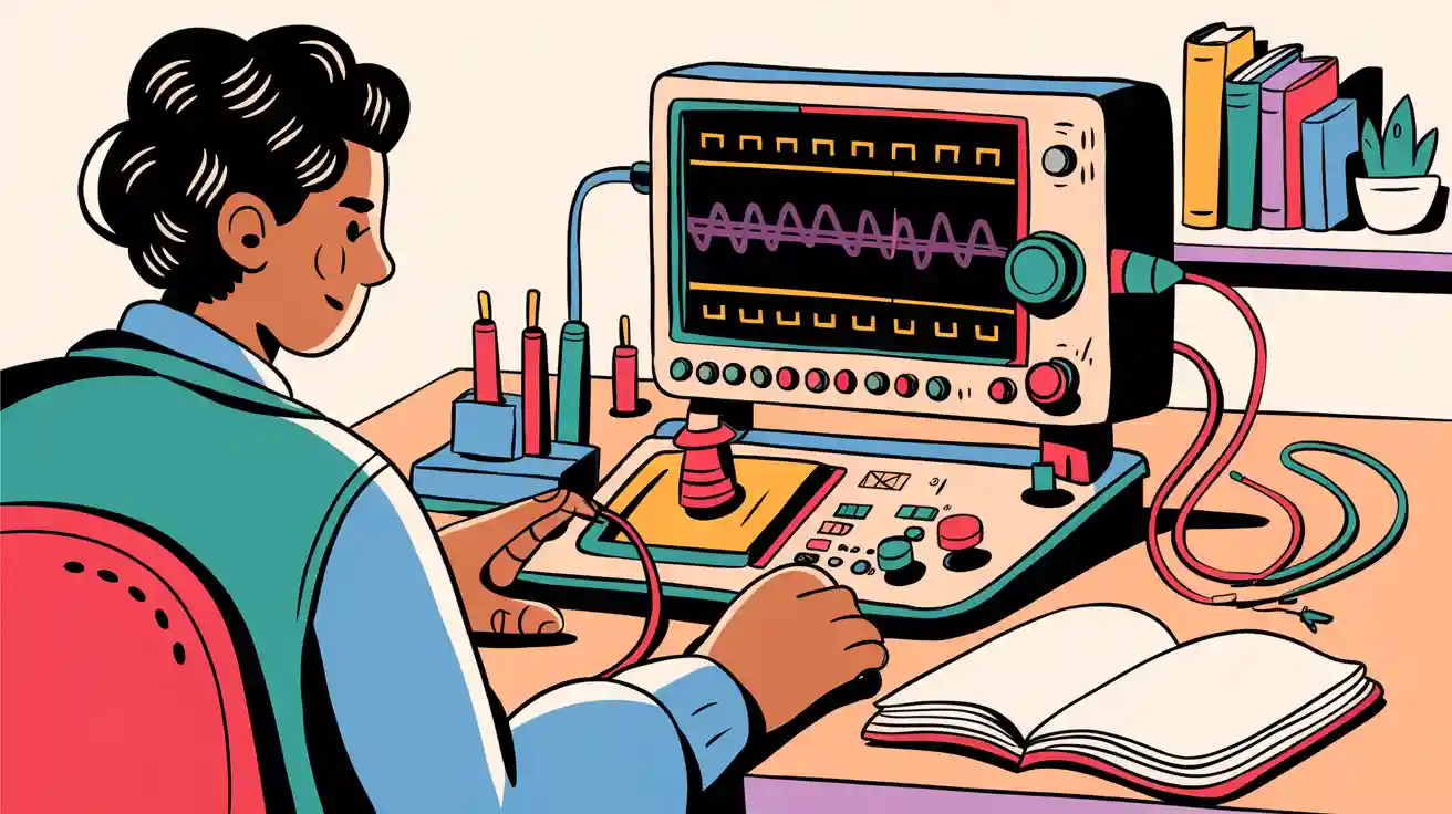
Have you ever tried fixing a blinking LED circuit and wondered why it just won’t work? You grab an oscilloscope, and suddenly, you see the hidden world of electrical signals. That’s what is an oscilloscope: a tool that lets you visualize voltage changes over time. When you learn how to use it, you solve problems faster and understand your projects better. You don’t need to feel intimidated—oscilloscopes make electronics easier and more fun!
Key Takeaways
- An oscilloscope visualizes electrical signals, helping you understand voltage changes over time. This tool simplifies troubleshooting and enhances your electronics projects.
- Use an oscilloscope to analyze signals, measure voltage levels, and troubleshoot circuit issues. It reveals problems that a multimeter might miss.
- Choose the right oscilloscope for beginners. Look for user-friendly features like automated measurements and clear instructions to aid your learning.
- Always prioritize safety when using an oscilloscope. Ensure proper grounding and check for damaged probes to avoid electrical hazards.
- Practice with simple projects to build your oscilloscope skills. Each project helps you gain confidence and understand how to measure and analyze signals effectively.
What Is an Oscilloscope
Definition
You might ask yourself, what is an oscilloscope? It’s a special tool that helps you see electrical signals as pictures on a screen. When you connect an oscilloscope to a circuit, it shows you how voltage changes over time. This makes it easier to understand what’s happening inside your project.
Here’s a quick look at what is an oscilloscope, based on leading electronics textbooks:
| Aspect | Description |
|---|---|
| Definition | An oscilloscope is a laboratory instrument commonly used to display and analyze the waveform of electronic signals. |
| Function | It draws a graph of the instantaneous signal voltage as a function of time. |
| Usage | Widely used in various fields, including physics, engineering, and electronics. |
| Properties | Allows analysis of wave properties such as speed, amplitude, frequency, and period. |
When you use an oscilloscope, you can see signals that change very quickly or slowly. Most entry-level oscilloscopes let you check signals from a few hertz up to 200 megahertz. This means you can use them for simple projects or more advanced ones.
How does an oscilloscope work? Let’s break it down:
- The oscilloscope takes in an electrical signal through its input.
- It boosts the signal so you can see it clearly.
- The horizontal part of the screen shows time, while the vertical part shows voltage.
- You can adjust the time scale to zoom in or out on the signal.
- The trigger helps keep the signal steady, so it doesn’t jump around.
Tip: Synchronization controls help you keep the signal still on the screen, just like a strobe light can freeze motion.
Purpose
So, what is an oscilloscope used for? You use it to solve problems, test new designs, and learn how circuits behave. If your project isn’t working, the oscilloscope can show you if the signal looks wrong or noisy.
Here’s why you might use an oscilloscope:
- Signal analysis
- Measuring voltage levels
- Testing circuit integrity
- Troubleshooting electronic circuits
Let’s look at some main purposes in a table:
| Purpose | Description |
|---|---|
| Troubleshooting | Identifying faults in electronic equipment by revealing oscillations or incorrect signals. |
| Checking New Designs | Analyzing newly designed circuits for design errors, voltage levels, and electrical noise. |
| Real-time Software Development | Monitoring missed deadlines and latencies during software development. |
You need an oscilloscope if you want to see what’s really happening inside your electronics. It helps you spot problems that you can’t see with just a multimeter. When you master what is an oscilloscope, you unlock a new way to explore and fix your projects.
Why Use an Oscilloscope
Importance
You might wonder why you should bother learning to use an oscilloscope. The answer is simple: it helps you see what’s really happening in your circuits. When you ask yourself what is an oscilloscope good for, think about all the times you’ve struggled to find out why a project isn’t working. An oscilloscope lets you spot problems that you can’t see with just a multimeter.
Oscilloscopes are essential for troubleshooting. If you ever face issues like no display, unstable signals, or distorted waveforms, you can use an oscilloscope to check what’s wrong. Here’s a quick guide to common problems and how you can use your scope to fix them:
| Problem | First Check | Then Try | Last Resort |
|---|---|---|---|
| No display | Power, intensity, vertical settings | Different probe, factory reset | Service center |
| Unstable signal | Trigger settings, probe connection | Trigger coupling, holdoff | External triggering |
| Distorted waveform | Probe compensation, ground lead | Bandwidth limitations, sample rate | New probe or scope |
| Inaccurate readings | Calibration, probe attenuation setting | Self-test, verification signal | Professional calibration |
| Intermittent issues | Cable connections, environment | Different power source, location | Service center |
Tip: When you use an oscilloscope, you can quickly check each part of your circuit and find the exact spot where things go wrong.
Benefits
Learning to use an oscilloscope gives you a big advantage. You can measure signals in real time and compare different parts of your circuit. This helps you find timing problems and see how signals interact. You can even work with friends or teachers remotely, since many digital oscilloscopes let you share what you see.
Here are some benefits you’ll notice as a beginner:
| Benefit | Description |
|---|---|
| Analyze time-varying signals | You can watch how signals change over time, which helps you understand your circuit. |
| Measure frequency and amplitude | You can find out how strong and how fast your signals are. |
| Diagnose circuit issues | You get detailed information that helps you fix problems quickly. |
You’ll also be able to:
- Determine the frequency and amplitude of signals.
- Spot noise in your circuit.
- Recognize different waveform shapes, like sine or square waves.
- Measure phase differences between signals.
Note: Using an oscilloscope makes you faster and more accurate when you troubleshoot. You don’t have to guess what’s wrong—you can see it right on the screen.
Types of Oscilloscopes
Analog vs. Digital
When you start learning about oscilloscopes, you will see two main types: analog and digital. Each type works in a different way. Analog oscilloscopes show signals in real time. You see the waveform as it happens, thanks to an electron beam inside the screen. Digital oscilloscopes take a different approach. They sample the signal, turn it into digital data, and then rebuild the waveform for you to see.
Here’s a quick table to help you compare the two:
| Feature | Analog Oscilloscope | Digital Oscilloscope |
|---|---|---|
| Signal Processing | Direct display with electron beam | Samples and digitizes signals |
| Bandwidth (BW) | Limited bandwidth | Higher bandwidth available |
| Sample Rate | Not applicable | Shows how fast data is captured |
| Memory Depth | No waveform storage | Stores waveforms for later viewing |
| Resolution (ADC Bits) | Not applicable | Higher resolution for clearer signals |
| Trigger | Basic controls | Many trigger modes for better measurements |
You might wonder which one is better for you. Analog scopes give you a live view, which feels simple and direct. Digital scopes offer more features, like saving signals and zooming in on details. You can even use advanced tools to study the frequency of your signals.
Tip: Digital oscilloscopes let you pause, zoom, and analyze signals. This makes them great for learning and troubleshooting.
Here’s a quick summary:
- Analog scopes show signals instantly.
- Digital scopes let you store, analyze, and share waveforms.
Choosing for Beginners
If you are just starting out, picking the right oscilloscope can feel tricky. You want something easy to use and helpful for learning. Look for a model with a simple interface. Big buttons and clear menus make it easier to understand what you see on the screen.
Here are some things you should consider:
- Choose an oscilloscope with automated measurements. This saves you time and helps you avoid mistakes.
- Look for advanced analysis tools, like FFT, if you want to study signal frequencies.
- Pick a design with clear instructions and on-screen help. Some models even offer tutorials.
- Make sure the oscilloscope supports your language. Multilingual support helps you learn faster.
- Buy from a trusted brand. Good support and warranties give you peace of mind.
Note: You don’t need the most expensive oscilloscope to get started. A basic digital model with easy controls and helpful features will help you learn and grow.
If you follow these tips, you will find an oscilloscope that fits your needs and helps you master electronics.
Components and Controls
Display
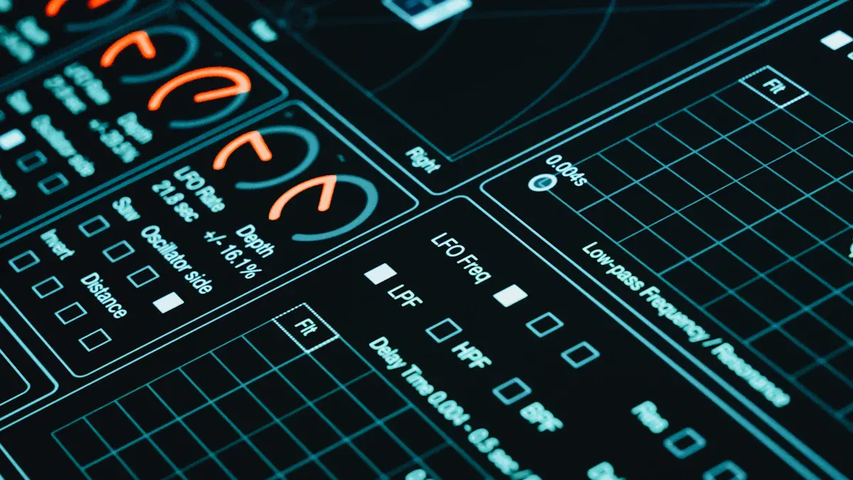
When you look at an oscilloscope, the display is the first thing you notice. This screen shows you the electrical signals as waveforms. You can watch the signal move in real time, or you can freeze it to take a closer look. The display helps you measure things like voltage and frequency right on the screen.
- The oscilloscope lets you:
- Plot signal waveforms live.
- Capture and hold a waveform for detailed study.
- Use trigger controls to keep the signal steady.
- See automatic measurements, such as voltage and frequency.
- Decode data signals, which is helpful for troubleshooting.
A stable display is important. If the signal drifts, it becomes hard to read. The oscilloscope uses synchronization to keep the waveform steady. This makes it easier for you to analyze and measure signals.
Tip: Always check the display settings before you start measuring. A clear and stable screen makes your work much easier.
Probes
Probes connect your oscilloscope to the circuit. You have different types of probes for different jobs. Here’s a quick guide:
| Probe Type | Description |
|---|---|
| Voltage or Current | Measures voltage or current signals. |
| Passive | Simple and affordable, good for most basic tasks. |
| Active | Handles high-frequency signals, great for advanced projects. |
| Single-ended or Differential | Single-ended measures one point; differential measures between two points. |
| High-Voltage | Safely measures high voltages. |
You might use a passive probe for most beginner projects. If you need to measure fast or tiny signals, try an active probe. For high-voltage circuits, always use a high-voltage probe to stay safe.
Controls
Oscilloscopes have several control systems. You use these to adjust how the signal appears on the screen. The main controls are:
| Control System | What It Does |
|---|---|
| Horizontal System | Moves the signal left or right and changes the time scale. |
| Vertical System | Adjusts the height of the signal and sets how much voltage each division shows. |
| Triggering | Keeps the signal steady so you can measure it easily. |
Each oscilloscope model is a little different. Take time to read the manual. You will learn what each button and knob does. This helps you avoid mistakes and get the best results from your oscilloscope.
Note: Getting comfortable with the controls makes you faster and more confident when testing circuits.
Setup and Calibration
Safety
Before you start using your oscilloscope, safety comes first. You want to protect yourself and your equipment. Here are some important tips to keep in mind:
- Always make sure the oscilloscope and your circuit are properly grounded. This keeps you safe from electrical shock and helps you get accurate readings.
- Check your probes for any damage. Damaged probes can give you wrong results or even cause harm.
- Keep your workspace clean and dry. High humidity or extreme temperatures can mess with your measurements.
- Wear safety gear like gloves or grounding straps if you work with high voltages.
Tip: Always read the manufacturer’s safety instructions before you set up your oscilloscope. If you need to clean or change anything inside the oscilloscope, unplug it first.
Probe Connection
Connecting your probe the right way makes a big difference. Here’s a simple step-by-step guide:
- Find the test point in your circuit that you want to measure.
- Pick the right probe for your job. Most beginner projects use a passive probe.
- Plug the probe into the oscilloscope input.
- Attach the probe tip to your test point.
- Clip the ground lead to a good ground spot on your circuit. This reduces noise and interference.
- Adjust your oscilloscope settings so you can see the signal clearly.
- Use the controls to steady the waveform on the screen.
- Double-check your signal. If you see noise, try moving the ground clip or using noise reduction features.
- Save or write down your results for later.
Note: A secure ground connection helps you get a clean, accurate signal every time.
Calibration
Calibration makes sure your oscilloscope gives you correct results. When you calibrate, you match your oscilloscope’s settings to a known signal. This step is key for getting reliable data.
- Calibration helps you trust your measurements. You can make better decisions when you know your data is right.
- Always calibrate your probes, since they touch the signals directly.
Here’s how you can calibrate most entry-level oscilloscopes:
- Learn what each control does on your oscilloscope.
- Make sure all ports and connectors are clean.
- Turn on the oscilloscope.
- Check for any software updates.
- Adjust for room temperature and humidity if needed.
- Connect your probe to the input.
- Use the calibration terminal on the oscilloscope to test the probe.
- Adjust the display until the test signal looks right.
- Make any other tweaks needed.
- Compare your results with a reference signal.
- Write down your calibration results.
Remember: Proper setup and calibration help you get the most accurate and useful measurements from your oscilloscope.
Basic Measurements
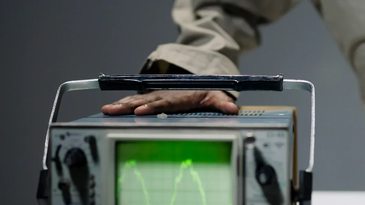
When you start using an oscilloscope, you unlock the power to measure voltage, frequency, and pulse width. These are the building blocks for understanding how your circuit works. Let’s break down each measurement so you can get hands-on right away.
Voltage
You want to know how strong your signal is. Measuring voltage with an oscilloscope is easy once you know what to look for. Here’s how you do it:
- Pick the right probe. Use a probe with minimal attenuation. This keeps your signal within the oscilloscope’s range and gives you a clear picture.
- Keep your ground leads short. Short ground leads help you avoid noise and keep your readings accurate.
- Try differential probes. If you’re working with floating signals, differential probes give you better accuracy.
Once you connect your probe, you’ll see the waveform on the screen. The vertical axis shows voltage. You can use the vertical sensitivity knob to zoom in or out. If your signal looks squished or stretched, adjust the amplitude so the waveform fills about three to six divisions on the screen.
Tip: If you see a fuzzy or shaky line, check your ground connection. A solid ground keeps your signal clean.
Frequency
Frequency tells you how fast your signal repeats. You can measure it by looking at the time between repeating parts of the waveform. Here’s what you need to know:
- Oscilloscopes capture the signal’s periods. You can use the time base to stretch or compress the waveform until you see three or four cycles across the screen.
- Accuracy depends on how steady your signal is. If your signal jitters or has noise, your measurement might jump around.
- You can average several captures to get a more stable reading. This helps smooth out errors, but don’t expect perfect accuracy for very high frequencies.
To measure frequency, use the cursors or the automatic measurement feature. Place one cursor at the start of a cycle and another at the end. The oscilloscope will show you the time difference. Divide one by this time to get the frequency.
Note: If you’re working with high-frequency signals, you might see more errors. Try averaging your measurements or using a scope with higher bandwidth.
Pulse Width
Pulse width shows you how long a signal stays high or low. This is important for digital circuits and timing checks. You can measure pulse width in a few simple steps:
- Trigger your oscilloscope so the pulse signal appears steady on the screen.
- Move the cursors to the rising and falling edges of the pulse.
- Read the time difference between the cursors. That’s your pulse width!
Many oscilloscopes let you select ‘Pulse Width’ from the menu. The scope will calculate it for you. If you want to see how pulse width changes over time, use the histogram function. This shows you a graph of all measured pulse widths, so you can spot patterns or problems.
Pro Tip: If your pulse width looks different every time, check for noise or unstable signals. A clean setup gives you more reliable results.
Adjusting Amplitude to View the Whole Waveform
Sometimes your signal doesn’t fit nicely on the screen. You need to adjust the amplitude and timing settings. Here’s a quick guide:
| Parameter | Description |
|---|---|
| Vertical sensitivity | Turn this knob to make the waveform taller or shorter. Aim for three to six divisions high. |
| Horizontal timing | Change the time per division so you see three to four cycles across the screen. |
| Trigger position | Set the trigger at the middle (50%) of the vertical amplitude for a stable display. |
If you adjust these settings, you’ll see the whole waveform clearly. This makes it easier to measure voltage, frequency, and pulse width.
😊 You’re now ready to measure signals like a pro! Try these steps on your next project and watch your confidence grow.
Practical Examples
Circuit Test
You want to see if your circuit works. Grab your oscilloscope and get ready to test. Let’s say you built a simple LED flasher. You connect the probe to the output pin of your microcontroller. The screen shows a square wave. That means your circuit sends regular on-off signals to the LED.
Here’s how you can test your circuit step by step:
- Power up your project.
- Connect the oscilloscope probe to the signal point.
- Attach the ground clip to a safe ground spot.
- Adjust the vertical and horizontal controls until you see a clear waveform.
You might notice the signal looks shaky. Check your ground connection. If the waveform is too small, turn up the vertical sensitivity. If you see a flat line, your circuit might not work. Try moving the probe to another spot or check your wiring.
Tip: If you see a clean square wave, your LED flasher works. If the wave looks strange, you can spot problems before you even touch the hardware.
Testing circuits with an oscilloscope helps you catch mistakes early. You save time and avoid frustration.
Sensor Signal
You can use an oscilloscope to explore sensor signals. Imagine you have a temperature sensor in your project. You want to know if it sends the right data. Connect the probe to the sensor output. Watch the waveform change as the temperature shifts.
Oscilloscopes help you do more than just see the signal. You can:
- Debug sensor signals and find issues.
- Analyze the shape of the waveform.
- Measure how often the signal changes.
- Monitor voltage levels from the sensor.
Here’s a quick table to show what you can do:
| Application Type | Description |
|---|---|
| Signal debugging | Helps you spot problems in sensor signals. |
| Waveform analysis | Lets you see the shape of the signal. |
| Frequency measurement | Shows how often the signal repeats. |
| Voltage monitoring | Tells you the voltage level from the sensor. |
You might see a smooth curve if the sensor works well. If the signal jumps or drops, you know something’s wrong. You can fix problems faster and learn how sensors behave in real time.
😊 Using an oscilloscope with sensors makes your projects smarter and more reliable. Try it out and watch your skills grow!
Troubleshooting
No Signal
You turn on your oscilloscope, but nothing shows up. Don’t panic! This happens to everyone. You can fix it by checking a few common problems:
- Probe connections might be loose or in the wrong spot.
- The signal amplitude could be too low for the oscilloscope to detect.
- Oscilloscope settings may not match your signal.
Try these steps if you still see no signal:
- Connect the oscilloscope directly to your signal generator. This helps you spot short circuits.
- Press the Autoset button after you confirm the probe compensation signal is visible.
- Adjust the vertical and horizontal scales so the waveform fits the screen.
Tip: Always double-check your probe and ground connections before you start measuring. A simple mistake can hide your signal.
Probe Errors
Probes can cause trouble if they aren’t set up right. You want your probe to send the signal to the oscilloscope without changing it. Here’s how you can spot and fix probe errors:
- Calibrate your probe. Compare its readings to a known signal. This shows if the probe is accurate.
- Adjust the probe if calibration shows a problem. You might need to fine-tune settings or make small changes.
Pick a probe that matches your project. It should pass the signal faithfully and avoid disturbing the test point. If you notice strange waveforms or wrong measurements, check your probe first.
Note: Always use the probe recommended for your oscilloscope. This helps you get the best results.
Noisy Signals
Sometimes your signal looks messy or jumps around. Noise can make it hard to see what’s happening. You can clean up your signal using these techniques:
| Technique | Description |
|---|---|
| Bandwidth Limit Filter | Cuts out high-frequency noise by reducing the oscilloscope’s bandwidth. |
| Average Acquisition Mode | Averages several signal captures to cancel random noise. |
| Math Filter (FilterVu) | Uses a low-pass filter to remove certain noise frequencies from your signal. |
Try these methods if your signal looks fuzzy. You’ll get a clearer picture and better measurements.
😊 Troubleshooting with your oscilloscope gets easier with practice. Keep testing and learning, and you’ll solve problems faster every time!
Further Learning
Resources
You want to keep growing your oscilloscope skills. Great news! Many beginner-friendly resources can help you learn more and practice new techniques. You can find guides, videos, and interactive tools online. Here are some top picks to get you started:
- Oscilloscope Basics: A Beginner's Guide
This guide explains the most important oscilloscope features. You get tips and tricks for using your scope in real projects. The language stays simple, so you never feel lost. - YouTube Tutorials
You can watch step-by-step videos. These show you how to set up your oscilloscope, connect probes, and measure signals. You see real examples and learn by watching. - Manufacturer Manuals
Every oscilloscope comes with a manual. You find details about controls, safety, and troubleshooting. Reading the manual helps you avoid mistakes. - Online Forums
You can ask questions and share your experiences. Other beginners and experts give advice and solutions. You learn from real problems and get support.
Tip: Bookmark your favorite resources. You can return to them when you need help or want to review a tricky topic.
Practice Projects
You learn best by doing. Try these simple projects to build your confidence and skills. Each project lets you use your oscilloscope in a new way.
| Project Name | What You Learn | Materials Needed |
|---|---|---|
| LED Blinker Test | Measure square waves | Breadboard, LED, resistor, microcontroller |
| Audio Signal Check | View sound waveforms | Audio source, speaker, wires |
| Sensor Output Watch | Track changing voltages | Temperature sensor, battery, wires |
| Power Supply Ripple | Spot unwanted noise | Power supply, wires |
You can start with the LED blinker. Connect your oscilloscope and watch the signal change as the LED flashes. Move on to audio signals and see how music looks as a waveform. Try a sensor project and notice how the output shifts with temperature. Test your power supply and find any hidden noise.
😊 Every project helps you master a new skill. You get better with each experiment. Keep practicing and enjoy the journey!
You’ve explored the basics of using an oscilloscope. Now you can measure signals, troubleshoot circuits, and test your ideas. Every time you practice, you get better. Mastering these skills opens doors to advanced electronics and exciting projects.
Ready to share your story or ask a question? Drop your thoughts below! Remember, every expert started as a beginner. Keep experimenting and watch your confidence grow. 🚀
FAQ
How do you read a waveform on an oscilloscope?
You look at the screen. The vertical axis shows voltage. The horizontal axis shows time. You watch the shape of the wave to see how your signal changes.
Can you use an oscilloscope to measure current?
You need a current probe. Most oscilloscopes measure voltage. If you connect a current probe, you can see current waveforms just like voltage.
Why does my oscilloscope show a flat line?
Your probe might not connect right. The signal could be missing. Check your connections. Make sure your circuit works. Try adjusting the vertical scale.
What does the trigger do on an oscilloscope?
The trigger keeps your signal steady on the screen. You set the trigger level. The oscilloscope waits for your signal to reach that point before drawing the wave.