What Are Decoupling Capacitors and Why You Need Them
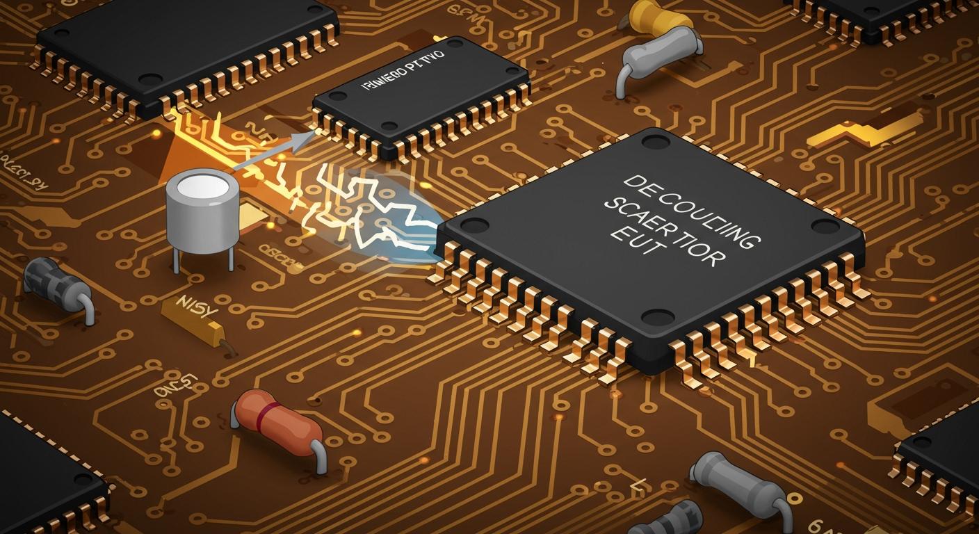
Think of a decoupling capacitor as a tiny, local power reservoir for an integrated circuit (IC) 🔋. You need decoupling capacitors to perform two critical jobs.
They provide instant current to ensure voltage stability, and they filter high-frequency electrical noise to deliver clean power.
Modern ICs have incredibly fast signal rise times. This fast switching creates noise that can reach well into the gigahertz range. Using decoupling capacitors correctly is a fundamental step. It ensures your electronic circuits operate reliably and without strange glitches.
Key Takeaways
- Decoupling capacitors act like small power banks for computer chips. They give instant power when chips need it fast.
- These capacitors also clean up electrical noise. This noise can make circuits work wrong.
- Place decoupling capacitors very close to the chip's power pins. This helps them work best.
- Use small ceramic capacitors, like 0.1µF, for each chip. They are good for cleaning high-speed noise.
- Always check the chip's instructions for the best capacitor choices. This helps your circuit run well.
THE ROLE OF A DECOUPLING CAPACITOR
To truly appreciate decoupling capacitors, you need to understand the two main problems they solve in your electronic circuits. They are the unsung heroes that work tirelessly to maintain power purity and stability.
STABILIZING POWER SUPPLY VOLTAGE
Imagine your integrated circuit (IC) is an athlete running a sprint. It needs huge bursts of energy instantly. Your main power supply is like the team's water cooler, located far away on the sidelines. When the IC suddenly gets "thirsty" for a large amount of current, the power supply cannot deliver it fast enough due to the distance and inductance of the circuit board traces.
This delay causes the voltage at the IC's power pin to drop temporarily. This is a "voltage droop" or a mini-brownout. If the voltage drops too low, the IC can malfunction, reset, or produce errors.
A decoupling capacitor acts like a personal water bottle strapped right to the athlete. It's a local reservoir of charge placed right next to the IC. When the IC demands a quick burst of current, the capacitor supplies it instantly. This action maintains excellent voltage stability right where it matters most.
NOISE IN ELECTRONIC CIRCUITS
Modern digital electronic circuits are noisy places. The primary source of this noise is the very thing that makes them work: fast-switching digital signals. Every time a logic gate switches from 0 to 1 or 1 to 0, it draws a tiny spike of current. When millions of gates in a microprocessor switch millions of times per second, they create a storm of high-frequency electrical noise on the power supply lines.
This noise can come from many sources, impacting your circuit's signal integrity. Common culprits include:
- High-frequency clock signals and their harmonics
- Switching power supplies and DC/DC converters
- Electric motors
- High-speed communication interfaces like Ethernet or USB
This electrical noise is a major problem. It can cause one part of your circuit to interfere with another, leading to unpredictable behavior. As an example, excessive power supply noise can falsely trigger a system reset, causing your device to get stuck in an unstable loop of restarting. This is why effective noise filtering is essential for reliable operation.
FILTERING HIGH-FREQUENCY NOISE
So, how does a simple capacitor fight this high-frequency noise? It all comes down to a property called impedance. Think of impedance as electrical resistance, but for AC signals like noise. A capacitor's impedance changes with frequency.
- At low frequencies (like DC power): A capacitor has very high impedance. It acts like an open door, letting the steady DC voltage pass through to the IC without issue.
- At high frequencies (like electrical noise): A capacitor has very low impedance. It acts like a shortcut to the ground plane.
This characteristic makes a decoupling capacitor the perfect tool for noise filtering. You place it between the power and ground lines. The capacitor allows the clean DC power to flow to the IC but diverts the unwanted high-frequency noise away from the IC and safely shunts it to ground. This improves the overall signal integrity of the system.
DECOUPLING VS. BYPASS CAPACITORS
You will often hear the terms "decoupling capacitors" and "bypass capacitors" used to describe the same component. While they are functionally identical, the names describe two sides of the same job. Many engineers use the terms interchangeably, but understanding the distinction can clarify their purpose. The use of bypass capacitors is a fundamental technique.
Decoupling: This term focuses on the capacitor's role in isolating or "decoupling" one part of a circuit from another. The goal of decoupling capacitors is to prevent noise from an IC from getting onto the power rail and affecting other components. These decoupling capacitors are essential.
Bypassing: This term focuses on the capacitor's role in shunting or "bypassing" noise. You use bypass capacitors to provide a low-impedance path for high-frequency noise to go from the power line to ground, bypassing the IC. All decoupling capacitors are also bypass capacitors.
Ultimately, whether you call them decoupling capacitors or bypass capacitors, their job is the same. A decoupling capacitor provides local energy storage, and these bypass capacitors clean up noise. For robust designs, you need both functions, and thankfully, bypass capacitors provide them. Good design practice always includes bypass capacitors. These bypass capacitors are non-negotiable for modern electronic circuits.
PLACING DECOUPLING CAPACITORS CORRECTLY
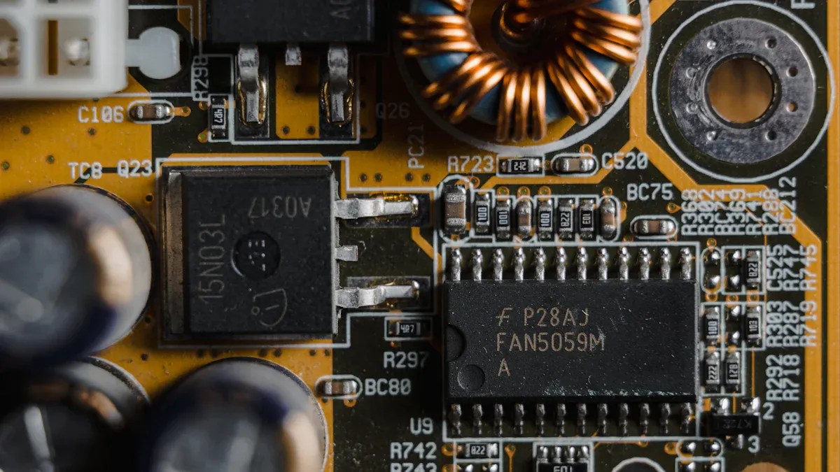
You now know that decoupling capacitors are essential. However, a poorly placed decoupling capacitor is almost as useless as no capacitor at all. Placement is the single most critical factor for making these components work effectively in your electronic circuits.
THE IMPORTANCE OF PROXIMITY
The main goal is to deliver charge to the IC as fast as possible. Any distance between the capacitor and the IC adds wire length, which creates unwanted inductance. Inductance resists changes in current, slowing down the capacitor's response.
The Golden Rule: You must place decoupling capacitors as physically close as possible to the IC's power (VCC) and ground (GND) pins. This minimizes the path the current must travel.
Think of it as closing the distance between the athlete and their water bottle. A shorter path means a faster response and a more stable voltage for your IC. This is the primary job of these bypass capacitors.
A PRACTICAL PLACEMENT GUIDE
Properly placing bypass capacitors depends on the IC package you are using. Your goal is always to make the decoupling loop area as small as possible.
- For QFP packages: You should distribute bypass capacitors around all sides of the IC that have power pins. Placing at least one of the bypass capacitors on each side shortens the path to the nearest energy source.
- For BGA packages: You will often place bypass capacitors on the underside of the board, directly beneath the IC. You should use as many bypass capacitors as space allows, connecting them with vias close to the capacitor pads and BGA balls. Using multiple vias in parallel for bypass capacitors can cut inductance significantly.
MINIMIZING INDUCTANCE
Inductance is the enemy of good decoupling. Every millimeter of a circuit trace adds parasitic inductance, which limits the effectiveness of your bypass capacitors at high frequencies. Even the component's physical size matters.
- Smaller capacitor packages have lower internal inductance. An 0402 package is better than an 0603, which is better than an 0805.
- The vias connecting your bypass capacitors to power and ground planes also add inductance. A via's inductance increases with its length.
The total inductance of a trace is a complex calculation. It shows that inductance increases with length.
For a rectangular conductor, inductance per unit length can be calculated as:
L' = (μ0/π) * (1/w + 0.5 + ln(2h/w))This formula confirms that longer traces (which increase total
L) are something you must avoid for effective bypass capacitors.
THE ROLE OF A GROUND PLANE
A solid ground plane is your best friend for improving signal integrity. It acts as a massive, low-impedance return path for electrical noise. When your decoupling capacitor shunts high-frequency noise, that noise needs an easy path back to the power source's ground. A continuous ground plane provides a direct highway for this current.
You must avoid creating splits or gaps in your ground plane under an IC. A gap forces the return current to take a long, roundabout path. This increases inductance and defeats the purpose of your carefully placed bypass capacitors. A good ground plane ensures your bypass capacitors can effectively clean up noise and maintain excellent signal integrity.
HOW TO CHOOSE THE RIGHT COMPONENTS
Selecting the right components is just as important as placing them correctly. You need to consider the capacitor's type, value, and other key properties to ensure your decoupling capacitors perform their job effectively.
COMMON CAPACITOR TYPES
You will encounter several types of capacitors, but for decoupling, one type stands out. Multi-Layer Ceramic Capacitors (MLCCs) are the standard choice for bypass capacitors because of their excellent high-frequency performance and small size. However, other types have their place.
| Feature | Ceramic Capacitor | Tantalum Capacitor | Aluminum Electrolytic Capacitor |
|---|---|---|---|
| Dielectric | Ceramic material | Tantalum pentoxide | Thin oxide layer |
| Construction | Non-polarized discs | Polarized nodes | Polarized, metal plates |
| Reliability | Very reliable | Stable performance | High capacitance for size |
MLCCs are great for high-frequency bypass capacitors, but they are not perfect. They are mechanically fragile and their capacitance can change with temperature and voltage.
SELECTING CAPACITANCE VALUE
You might see old advice suggesting multiple capacitor values for each IC. This is often not necessary for modern designs. A good starting point for most digital electronic circuits is a two-capacitor strategy.
- A 0.1µF ceramic capacitor for high-frequency noise. These are essential bypass capacitors.
- A 10µF bulk capacitor for lower-frequency power supply changes.
Pro Tip 💡: The best advice comes directly from the source. Always consult the IC manufacturer's datasheet for their specific recommendations on decoupling capacitors.
CHOOSING A VOLTAGE RATING
You should always choose a capacitor with a voltage rating higher than your circuit's voltage. A good rule is to select a rating at least double your operating voltage. This isn't just for safety. For Class 2 ceramic bypass capacitors (like X7R or X5R), applying a DC voltage dramatically reduces their effective capacitance. This is called the DC bias effect. A 10V-rated capacitor on a 5V rail might lose over 50% of its capacitance. Using a 25V or 35V rated part helps ensure you get the capacitance you need for good signal integrity.
KEY CAPACITOR PROPERTIES (ESR & ESL)
Ideal capacitors don't exist. Real bypass capacitors have parasitic properties that affect their performance.
- Equivalent Series Resistance (ESR): This is the internal resistance of the capacitor. Lower ESR is better.
- Equivalent Series Inductance (ESL): This is the inductance from the capacitor's internal structure and leads. Lower ESL is critical for high-frequency decoupling capacitors.
These properties limit how well bypass capacitors can filter noise. To minimize ESL, you should always use smaller capacitor packages like 0603 or 0402.
USING MULTIPLE CAPACITORS
However, be careful. Combining different bypass capacitors can create "anti-resonance," a frequency point where their combined impedance is very high. This can make noise problems worse. To avoid this, use capacitors with similar values in parallel when possible. This ensures your decoupling capacitors work together, not against each other.
A successful circuit design requires decoupling capacitors. They are a non-negotiable part of modern electronics. These bypass capacitors perform two critical jobs. They act as a local energy reserve to prevent voltage drops. Effective bypass capacitors also stop noise from affecting other circuits. Your design needs these decoupling capacitors for stability.
For a reliable circuit, always follow this rule: Place a 0.1µF ceramic decoupling capacitor as close as possible to every IC's power and ground pins. These bypass capacitors are essential.
FAQ
Why is 0.1µF the most common value?
The 0.1µF (or 100nF) ceramic capacitor offers a great balance. It has very low impedance at the high frequencies where most digital ICs create noise. This value effectively filters noise for a wide range of common electronic circuits, making it an excellent default choice.
Do I really need a capacitor for every single IC?
Yes, you should use a decoupling capacitor for every IC. Each chip creates its own electrical noise and needs a local energy source. Skipping a capacitor can lead to unstable operation and mysterious glitches that are very difficult to debug later.
Remember: A few cents for a capacitor saves you hours of frustration! 💡
What happens if I place the capacitor too far away?
Placing a capacitor far from an IC adds extra wire length. This length creates inductance, which acts like a barrier to fast current. The capacitor cannot respond quickly enough to stabilize the voltage. This makes the capacitor much less effective at its job.
Can I use one large capacitor instead of many small ones?
No, this is not a good practice. Large capacitors (like 10µF) are great for low-frequency power stability. However, they cannot filter high-frequency noise effectively. You need the small 0.1µF capacitors right next to each IC to handle the fast noise spikes.