Why VCC Matters Understanding Its Meaning and Application

You often see VCC when you read a circuit diagram. VCC meaning stands for the voltage at the common collector. In most cases, you use VCC as the main power source for your electronic devices. This voltage helps your circuit work by giving energy to the parts that need it. You connect VCC to the positive side and ground to the negative side. When you understand VCC, you can spot power and supply lines, which makes building or fixing circuits much easier.
Key Takeaways
- VCC means the positive supply voltage that powers parts of electronic circuits, especially the collector terminal in bipolar junction transistors.
- You find VCC labeled in schematics to show where to connect the positive power supply, making circuit building and troubleshooting easier.
- Different circuits use different VCC voltages, like 3.3V or 5V for digital devices and higher voltages for analog circuits; always check your device datasheet.
- VCC differs from terms like VDD, VSS, and VEE, which relate to other transistor types or ground connections; use the correct label to avoid mistakes.
- Keep VCC stable by using decoupling capacitors and proper PCB design; clear labeling and correct connections protect your circuit and ensure reliable operation.
VCC Meaning
What Is VCC?
You often see the term VCC when you work with electronics. VCC meaning stands for "Voltage at the Common Collector." This term comes from the world of bipolar junction transistors (BJTs). According to the IEEE standard, the letter "V" means voltage, and the double "C" shows that this is the supply voltage at the collector terminal, not just the voltage at the collector itself. You use VCC to describe the positive supply voltage that powers the collector of an NPN transistor. This supply gives energy to the circuit and helps it run as designed.
You will notice that VCC appears in many schematics. Designers use it to label the positive side of the power supply. You connect VCC to the parts of your circuit that need a positive voltage. The ground, marked as GND, connects to the negative side. In most diagrams, you see VCC as a label or a line that links to the positive terminal of the battery or power source. You do not need to draw every wire because the VCC label shows that all these points connect together.
Tip: When you read a schematic, look for the VCC label. It helps you find the main supply voltage quickly.
Origin of the Term
The term VCC has a long history in electronics. It first appeared in the 1960s, during the rise of bipolar transistor circuits. Early logic circuits used NPN transistors, and VCC meant the positive supply voltage connected to the collector terminal. This naming system helped engineers know which part of the transistor the supply powered. The double "C" in VCC set it apart from VC, which only shows the voltage at the collector, not the supply voltage.
You can trace VCC back to the first bipolar transistors, invented in 1947. Engineers used VCC in logic circuits to show the positive supply. Over time, even as new devices like MOSFETs appeared, VCC stayed popular. Today, you sometimes see VCC used for any positive supply rail, even in circuits that do not use BJTs. This tradition shows how important VCC meaning is in electronics.
Common Voltage Levels
You will find different VCC values in various types of circuits. The supply voltage depends on the device and its needs. Here is a table that shows common VCC values in different applications:
| Application Type | Common VCC Voltage Values |
|---|---|
| Consumer Electronics | 3.3V, 5V |
| Low-Power Embedded Systems | 1.8V |
| Industrial Equipment | 12V, 24V |
| Microcontroller Circuits | 3.3V, 5V |
In analog circuits, you may see higher or even bipolar supply voltages, such as ±15V. These higher voltages help analog devices like operational amplifiers work well. In digital circuits, VCC usually means a lower, single positive voltage, such as 3.3V or 5V. Microcontrollers and logic chips often use these values. Some mixed-signal devices use more than one supply voltage, with VCC for analog parts and other labels for digital sections.
Note: Always check the datasheet for your device. The correct VCC value keeps your circuit safe and working as expected.
VCC in Circuits
Powering Components
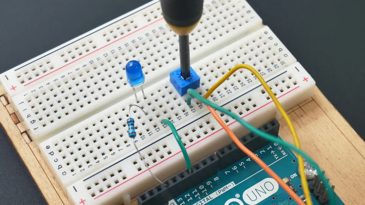
You use VCC to deliver power to many parts of your electronic circuit. When you look at a datasheet, you find a VCC pin on most transistors and integrated circuits. You connect this pin to the positive terminal of your power supply. The ground pin links to the common ground in your circuit. This setup lets current flow and gives energy to the components. You often place decoupling capacitors near the power pins to keep VCC stable and reduce noise. If your circuit draws a lot of current, you may need heat sinks or fuses to protect your devices. Always match the voltage of VCC to the needs of your components. This careful connection helps your microcontroller circuit and other devices work safely and reliably.
Tip: Stable VCC keeps your circuit running smoothly. Use decoupling capacitors and check your power supply ratings.
Digital vs. Analog Use
VCC plays a key role in both digital and analog circuits. In digital designs, such as TTL logic, VCC powers the transistors that switch signals on and off. You use VCC to enable digital switching and signal amplification. In analog amplifier circuits, VCC provides the supply voltage needed for continuous signal amplification. Operational amplifiers and BJTs rely on VCC to boost analog signals. The main difference is how you use VCC: digital circuits need it for switching, while analog circuits need it for smooth amplification. You see VCC labeled in schematics, showing where to connect the positive supply and ground.
- Digital circuits: VCC supports switching and logic operations.
- Analog circuits: VCC powers amplifiers for signal processing.
Mixed-Signal Applications
Mixed-signal circuits combine digital and analog functions. You face new challenges with VCC in these designs. Noise on VCC can cause problems like jitter and signal errors, especially at high frequencies. Lower supply voltages and more complex chips make circuits sensitive to VCC noise. You must separate analog and digital power regions on your PCB and use a uniform ground plane. Decoupling capacitors help suppress switching noise. Star topology for power distribution and careful routing reduce interference. You avoid crossing analog and digital regions to keep signals clean. Good VCC management ensures your mixed-signal circuit works well and stays reliable.
Note: In mixed-signal designs, always test for VCC noise immunity. Use proper layout techniques to keep your power supply stable.
VCC vs VDD, VSS, VEE
Key Differences
You will often see the terms vcc, vdd, vss, and vee in circuit diagrams. Each one has a specific meaning based on the type of transistor and the role in the circuit. The main difference comes from which terminal the supply voltage connects to and whether it is positive or negative. Vcc vs vdd is a common question when you read schematics. Vcc stands for the positive supply voltage at the collector of a bipolar junction transistor (BJT). Vdd is the positive supply voltage at the drain of a MOSFET or CMOS device. Vss and vee both refer to the negative side or ground. Vss connects to the source terminal in MOSFETs, while vee connects to the emitter in BJTs.
Here is a table to help you compare vcc vs vdd, vss, and vee:
| Term | Transistor Type | Terminal | Voltage Reference | Typical Function/Application |
|---|---|---|---|---|
| VCC | BJT | Collector | Positive supply voltage | Positive power rail in BJT circuits, TTL, Op-Amps |
| VDD | MOSFET/CMOS | Drain | Positive supply voltage | Positive power rail in MOSFET/CMOS circuits, Op-Amps |
| VSS | MOSFET/CMOS | Source | Ground or negative supply voltage | Ground or negative rail in MOSFET/CMOS circuits |
| VEE | BJT | Emitter | Negative supply voltage or ground | Negative power rail in BJT circuits, Op-Amps |
Note: Vcc vs vdd both provide positive supply voltage, but you use them for different transistor types. Vss and vee usually act as ground or negative supply rails.
When to Use Each Term
You should use vcc when your circuit uses BJTs or TTL logic. This label shows the positive supply voltage connected to the collector terminal. You will see vcc in older designs and in many operational amplifier circuits. Use vdd for MOSFET or CMOS circuits, where the positive supply connects to the drain terminal. Vss is the ground or negative supply voltage for MOSFET and CMOS devices. Vee is the negative supply voltage or ground for BJTs and analog circuits, connected to the emitter.
- Use vcc in BJT-based circuits and TTL logic.
- Use vdd in MOSFET or CMOS-based circuits.
- Use vss for the ground or negative rail in MOSFET/CMOS designs.
- Use vee for the negative rail or ground in BJT and analog circuits.
You may find that modern circuits sometimes mix these terms. Always check the datasheet and schematic to see which label matches the supply voltage and ground in your design. Understanding vcc vs vdd helps you connect the right supply and avoid mistakes. Correct labeling keeps your circuit safe and easy to troubleshoot.
Identifying and Using VCC
Datasheets and Schematics
When you look at datasheets for microcontrollers or analog ICs, you often find VCC listed in the pin configuration. VCC usually marks the positive supply voltage pin. You should check the datasheet for the voltage range, polarity, and current capacity for this pin. Most datasheets also show the minimum and maximum supply voltage allowed. You will see instructions to connect the positive terminal of your power supply to VCC and the negative terminal to ground. Always look for recommended decoupling capacitors near VCC pins. These help keep the supply voltage stable.
In electronic schematics, VCC appears as a label or symbol, often with an arrow pointing up. This label tells you where to connect the positive supply voltage. Multiple VCC labels in a schematic mean the same power node, even if they are far apart. You should use standard symbols and keep power at the top and ground at the bottom of your schematic. This makes your design easier to read and reduces mistakes.
Tip: Always check the pin descriptions and electrical characteristics in the datasheet to make sure you connect VCC and ground correctly.
PCB Design Tips
When you design a PCB, you want to keep the VCC supply voltage clean and stable. Use solid power planes for VCC and ground to lower noise and impedance. Place decoupling capacitors close to each VCC pin. Wide traces help carry more current without heating up. If you use multilayer PCBs, keep separate planes for VCC and ground. This setup helps your power supply voltages stay steady, even in high-speed or high-current designs.
| Supply Type | BJT Label | FET Label | Other Labels |
|---|---|---|---|
| Positive Supply Voltage | VCC | VDD | V+ |
| Negative Supply Voltage | VEE | VSS | V- |
| Ground | GND | GND | 0 |
Label your VCC and ground connections clearly on the PCB. This helps you and others avoid confusion during assembly and troubleshooting.
Labeling and Safety
You should always label VCC and ground clearly on your board and in your documentation. If you use special labels, talk with your team or client to avoid mistakes. When you work with power supply voltages, check that your connections match the datasheet limits. Never exceed the maximum voltage for VCC, or you may damage your device. Use regulated supplies and add decoupling capacitors to protect your circuit.
Note: Always follow safety rules in the lab. Double-check your power supply voltages and connections before turning on the power. This keeps you and your devices safe.
You learned that VCC means the positive supply voltage in many circuits. Knowing how to label VCC and ground helps you avoid mistakes like loose connections or missing bypass capacitors. You can find tutorials and kits to help you practice safe wiring and power management. Experts believe new terms will appear as technology changes, so keep exploring power supply topics. Your understanding of VCC will help you build and troubleshoot circuits with confidence.
FAQ
How do you find VCC on a schematic?
Look for the VCC label, often shown with an upward arrow or a line connected to the positive side of the power supply. You can spot VCC at the top of most circuit diagrams.
What happens if you connect VCC incorrectly?
You may damage your components or cause the circuit to fail. Always check the datasheet and confirm the correct voltage before making connections. Use a regulated power supply for safety.
Is VCC the same as VDD?
No, VCC powers BJTs at the collector terminal. VDD supplies MOSFETs at the drain terminal. You should use the correct label for each transistor type.
| Label | Device Type | Terminal |
|---|---|---|
| VCC | BJT | Collector |
| VDD | MOSFET | Drain |
Can you use VCC for both analog and digital circuits?
Yes, you can use VCC in both analog and digital circuits. You must keep the supply voltage stable and clean. Decoupling capacitors help reduce noise and improve performance.
What is the safest way to test VCC in a circuit?
Use a multimeter to measure the voltage at the VCC pin. Check the reading against the datasheet value. Always turn off power before making changes to the circuit.