Essential USB A Pinout Information for Modern Projects
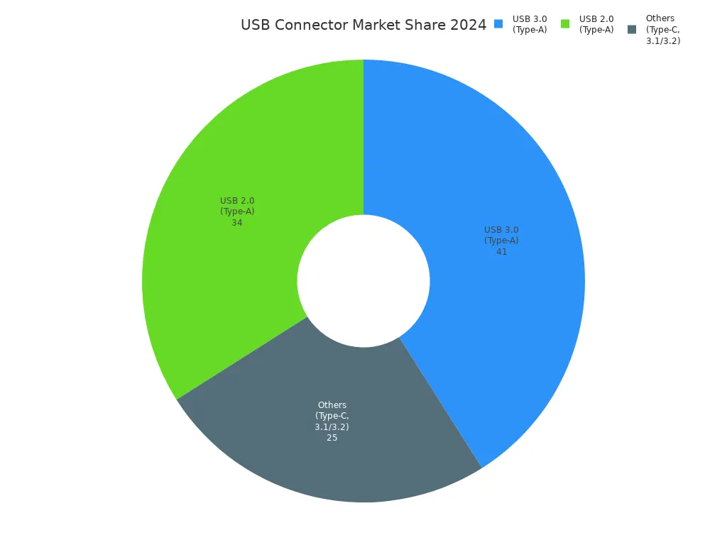
You often encounter the term usb a pinout when working with electronics. This pinout shows how each wire connects inside a universal serial bus Type-A connector. Knowing the pinout helps you wire devices safely and solve problems quickly. Universal serial bus Type-A connectors remain the most common, making up about 75% of modern device ports.
You can use clear pinout diagrams and tables to avoid common wiring mistakes. With a good understanding of usb a pinout, you improve your project’s success and ensure device compatibility.
Key Takeaways
- USB A connectors are common and connect many devices like keyboards, mice, and flash drives, so knowing their pinout helps you wire devices safely and avoid mistakes.
- The USB A pinout has four main pins: VBUS (red) for 5V power, D- (white) and D+ (green) for data transfer, and GND (black) for ground; matching wire colors to pins prevents wiring errors.
- USB 3.0 Type-A connectors add extra pins for faster data transfer but keep backward compatibility with USB 2.0, so always check your device’s pinout before wiring.
- Use shielded cables, proper tools, and follow pinout diagrams carefully when wiring or prototyping to ensure reliable connections and avoid damage.
- Troubleshoot USB issues by inspecting cables, testing voltage with a multimeter, and verifying correct pin connections to keep your projects safe and working well.
USB A Pinout Basics
Type-A Connector Overview
You see the type-a connector almost everywhere. It has a flat, rectangular shape and connects host devices like computers, laptops, and game consoles to many peripherals. The type-a connector is the original and most common USB connector. You use it to plug in keyboards, mice, flash drives, printers, and smartphones. The connector stays in place with friction, so you can insert and remove it easily.
The type-a connector supports many USB standards. You find it on both old and new devices. It provides a 5V DC power supply on one of its pins. The connector is not reversible, so you must align it correctly before plugging it in. Many beginners struggle with this because there are no clear signs to show the right way to insert it. Dark-colored ports and poor lighting make it even harder to see the orientation.
Here are some of the most common uses for the type-a connector:
| Use Case | Description |
|---|---|
| Data Transfer | Move files between computers and devices like flash drives, external hard drives, and printers. |
| Charging | Charge smartphones, tablets, and other rechargeable devices. |
| Connectivity | Connect keyboards, mice, webcams, and other peripherals to computers. |
| Audio | Use with headphones and microphones that have USB type-a connectors. |
| Networking | Connect to networks using Ethernet adapters. |
Tip: Always check the orientation of the type-a connector before inserting it. If it does not fit, flip it over and try again.
USB Pinout Diagram
The usb a pinout shows how each pin inside the connector works. You need to know the pinout to wire devices safely and avoid mistakes. The standard usb pinout for a USB 2.0 type-a connector has four main pins. Each pin has a specific function and a standard wire color.
Here is a clear usb pinout diagram for USB 2.0 type-a connectors:
| Pin Number | Pin Name | Function | Standard Wire Color |
|---|---|---|---|
| 1 | VBUS | 5V Power Supply | Red |
| 2 | D- | Data - | White |
| 3 | D+ | Data + | Green |
| 4 | GND | Ground | Black |
You use this usb pinout table to check your wiring and make sure each wire goes to the correct pin. The VBUS pin gives power to your device. The D- and D+ pins handle data transfer. The GND pin completes the circuit.
The usb pinout changes with newer standards. USB 3.0 type-a connectors add five more pins for faster data transfer. These extra pins support speeds up to 5 Gbps. The connector keeps the same shape, so you can still use it with older USB 2.0 ports. The extra pins sit deeper inside the connector and only connect when you use a USB 3.0 port.
Here is a comparison of USB 2.0 and USB 3.0 type-a pinouts:
| Pin Configuration Aspect | USB 2.0 Type-A | USB 3.0 Type-A |
|---|---|---|
| Number of Pins | 4 | 9 |
| Pin Functions | VBUS, D-, D+, GND | All USB 2.0 pins plus 5 extra for SuperSpeed data and power |
| Data Transfer Lines | One differential pair (D- and D+) | Two extra differential pairs for SuperSpeed |
| Maximum Data Rate | Up to 480 Mbps | Up to 5 Gbps |
| Backward Compatibility | Yes | Yes |
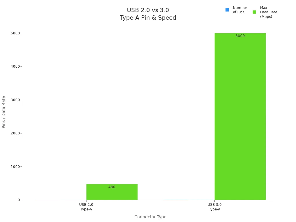
You can see that the usb pinout for USB 3.0 type-a connectors allows much faster data transfer. The connector still fits into older ports, so you do not lose compatibility. When you plan your project, always check which usb pinout your device uses. This helps you avoid wiring errors and ensures your project works as expected.
Note: The usb pinout diagram is your best friend when working with type-a connectors. Keep a copy nearby for quick reference.
USB Pinout Functions
Understanding the usb pinout helps you connect devices safely and transfer data without problems. Each pin in the usb connector has a special job. You need to know what each pin does to avoid mistakes in your projects. The four main pins—VBUS, D-, D+, and GND—work together to deliver power and send data.
Power and Ground Pins
The VBUS and GND pins handle power in the usb pinout. The VBUS pin supplies power from the host device, like a computer, to your usb device. According to the USB 2.0 specification, the VBUS pin provides a voltage of 5V with a tolerance of plus or minus 10 percent. The host must supply at least 500 mA for USB 2.0 ports. For USB 3.0 ports, the current goes up to 900 mA. This power is always available, even when the port is in suspend mode. When you first connect a device, it draws no more than 100 mA until the computer recognizes it. After that, the device can use the full current allowed by the port. This system keeps your devices safe and ensures they get the right amount of power.
The GND pin completes the electrical circuit. It acts as the return path for the current. Without a proper ground connection, your usb device will not work correctly.
You can identify these pins by their wire colors. The VBUS pin uses a red wire, and the GND pin uses a black wire. This color coding helps you check your wiring quickly.
| Pin | Wire Color | Function |
|---|---|---|
| 1 | Red | +5 V power (VBUS) |
| 4 | Black | Ground (GND) |
Most usb cables use wires with a gauge between 24 AWG and 28 AWG for power and ground. Thicker wires (lower AWG numbers) can carry more current. If you plan to charge devices or power larger circuits, choose cables with thicker wires for safety.
Tip: Always double-check the wire colors and pinout before connecting power. A mistake can damage your device.
Data+ and Data- Pins
The D+ and D- pins in the usb pinout handle all data communication. These pins form a differential pair, which means they work together to send and receive digital signals. The D+ pin uses a green wire, and the D- pin uses a white wire. This color coding makes it easy to spot the data lines in your usb cable.
- White wire (D-): Carries data signals in the negative direction.
- Green wire (D+): Carries data signals in the positive direction.
These two pins send data back and forth between your device and the host. The differential pair design helps reduce noise and electromagnetic interference. This setup keeps your data transfer smooth and reliable, even in busy environments.
| Pin No. | Wire Color | Signal | Description |
|---|---|---|---|
| 2 | White | D- | Data- pin used for carrying data signals in USB Type-A connectors |
| 3 | Green | D+ | Data+ pin responsible for data transmission in USB Type-A connectors |
Most usb cables use 28 AWG wires for the data lines. This size works well for short distances and keeps the signal strong. If you need longer cables, look for high-quality cables with good shielding to protect the data signals.
Note: If you mix up the D+ and D- wires, your usb device may not work or may transfer data slowly. Always follow the correct pinout and color codes.
The usb pinout gives you a clear map for wiring and troubleshooting. By understanding the function of each pin, you can build safer and more reliable projects.
Using USB Port Pinouts
Wiring and Prototyping
When you start a project with type-a connectors, you need the right tools and materials. You can use USB 2.0 Type-A to Type-B cables, which are usually six feet long and shielded. These cables have a 28AWG conductor gauge for both signal and power lines, making them reliable for prototyping. You also need through-hole USB connector boards with type-a USB receptacles, breadboards, and soldering accessories. Many people use straight type-a USB sockets, crocodile clips, jumper wires, PCBs, perfboards, SMT breakouts, wire, and heat shrink tubing.
Here is a quick list of helpful items for usb a wiring connection:
- Breadboards and perfboards
- Type-a USB sockets and connector boards
- Jumper wires and crocodile clips
- Soldering iron and accessories
- Shielded USB cables (Type-A to Type-B)
- Wire and heat shrink tubing
You should always follow the usb pinout diagram when wiring. Match the wire colors to the correct pins. Red goes to VBUS, black to GND, white to D-, and green to D+. This step helps you avoid mistakes and keeps your devices safe. If you use a breadboard, make sure each pin connects to the right spot. Double-check your connections before powering up your project.
Tip: Use shielded cables and good soldering practices to reduce interference and improve reliability.
Ensuring Compatibility
Understanding usb port pinouts helps you connect devices safely and avoid damage. You need to know the pinout for both USB 2.0 and USB 3.0 type-a connectors. USB 2.0 uses four pins, while USB 3.0 adds five more for faster data transfer. The extra pins allow speeds up to 5 Gbps and better power delivery. USB 3.0 connectors keep the original four pins, so you can use them with older ports.
| Pin Number | USB 2.0 Type A Function | USB 3.0 Type A Function (includes USB 2.0 pins) |
|---|---|---|
| 1 | +5V Power Supply (VCC) | +5V Power Supply (VCC) |
| 2 | Differential Data Line (D-) | Differential Data Line (D-) |
| 3 | Differential Data Line (D+) | Differential Data Line (D+) |
| 4 | Ground (GND) | Ground (GND) |
| 5 | N/A | SuperSpeed Receiver Differential Pair (negative) (StdA_SSRX-) |
| 6 | N/A | SuperSpeed Receiver Differential Pair (positive) (StdA_SSRX+) |
| 7 | N/A | Ground for signal return (GND_DRAIN) |
| 8 | N/A | SuperSpeed Transmitter Differential Pair (negative) (StdA_SSTX-) |
| 9 | N/A | SuperSpeed Transmitter Differential Pair (positive) (StdA_SSTX+) |
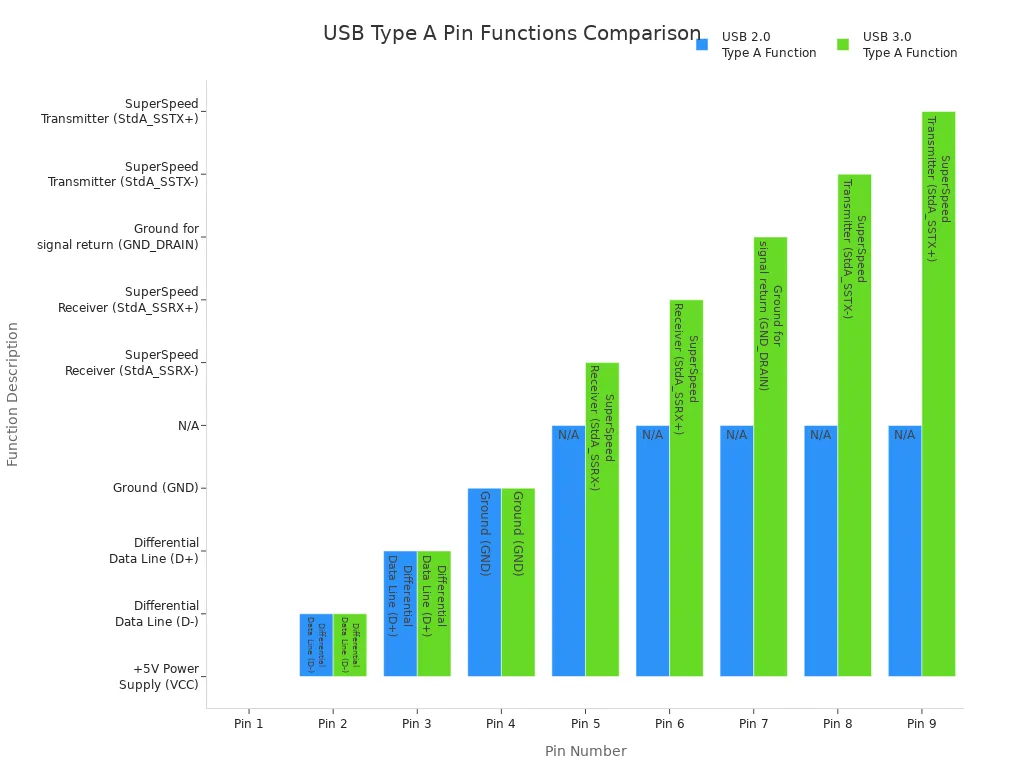
You may face compatibility issues if you mix different USB types or use outdated drivers. Sometimes, your device does not work because the USB function is disabled in BIOS or system settings. Unstable cables or faulty ports can cause frequent disconnections. Always check your usb pinout and use the right cable for your device. If you connect a USB 3.0 device to a USB 2.0 port, it will work but only at the lower speed.
Note: Knowing the pinout helps you select the right cables, adapters, and ports. This step prevents damage and ensures your devices communicate properly.
Troubleshooting USB Pinouts
Common Issues
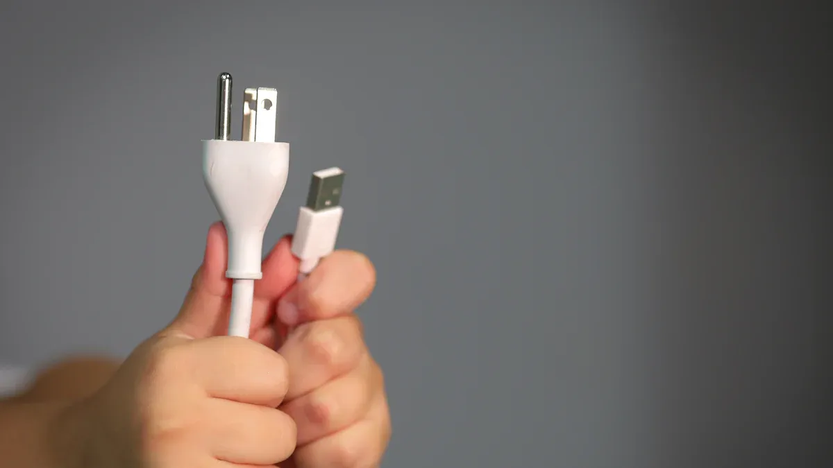
You may face several problems when working with usb pinout in your projects. Miswiring often causes unexpected voltage on the usb shield. In one case, a reversed wire made a computer’s usb shield carry 120 volts instead of being grounded. This led to electrical arcs, melted wires, and damaged circuit parts. You might see unstable circuit behavior, floating grounds, or reversed polarity. These issues can make your device act strangely or even become unsafe.
Physical damage is another common problem. Bent or broken pins inside the connector can stop your usb device from working. Poor connections may cause your device to disconnect or transfer data slowly. Sometimes, you notice charred components or melted wires. These signs point to serious wiring mistakes. Unstable cables and faulty ports also lead to frequent disconnections.
Here is a quick list of typical usb pinout problems:
- Miswiring or reversed polarity
- Poor ground connections
- Bent or broken pins
- Electrical arcing or melted wires
- Unstable or floating grounds
- Frequent device disconnects
Tip: Always inspect your cables and connectors before starting a project. Look for signs of damage or wear.
Diagnosing with Pinout Knowledge
You can solve most usb pinout problems by using the right tools and following expert steps. Start by checking if your cable provides power when plugged in. Use a cable tester to measure resistance; values under 2 Ohms are usually safe. Specialized usb multimeters help you test data transfer and protocol support. You should also check voltage and current between the ground and power pins. Expect 4.5 to 5.5 volts for most consumer electronics.
Try these steps to diagnose and fix pinout issues:
- Inspect the cable for physical damage or bent pins.
- Use a multimeter to measure voltage between ground and power pins.
- Test the cable with a cable tester to find opens or shorts.
- Check device settings and update drivers.
- Try the device on a different port or computer.
- Replace damaged cables or ports if problems continue.
| Diagnostic Tool | Purpose |
|---|---|
| Multimeter | Measure voltage between pins |
| Cable Tester | Check for opens, shorts, and resistance |
| USB Multimeter | Test data transfer and protocol support |
| Mechanical Test | Assess connector durability and reliability |
Knowing the pinout helps you find and fix problems quickly. You avoid unsafe wiring and keep your devices working well. Always use high-quality cables and never force connectors into ports.
Note: Pinout knowledge gives you the confidence to troubleshoot and repair usb circuits safely.
Quick Reference for USB Pinouts
USB Pinout Table
You can use this table as a quick guide when working with USB Type-A connectors. It shows the standard pinout arrangement, wire colors, and each pin’s function. This helps you avoid mistakes and makes your projects safer.
| Pin Number | Pin Name | Function | Standard Wire Color |
|---|---|---|---|
| 1 | VBUS | +5V Power | Red |
| 2 | D- | Data- | White |
| 3 | D+ | Data+ | Green |
| 4 | GND | Ground | Black |
Tip: Always check the pinout and wire colors before you connect or solder any USB cable. This step prevents miswiring and protects your devices.
Project Checklist
A checklist helps you plan and verify your USB wiring. You can prevent common pinout errors by following these steps:
- Assign net labels to each pin in your schematic. Use names like DP_IN for Data+ and DM_IN for Data- to keep track of differential pairs.
- Mark the polarity and orientation clearly in your assembly drawings. This helps you avoid reversed connections.
- Use polarized or keyed connectors. These connectors only fit one way, so you cannot plug them in wrong.
- Cross-check your parts list and footprints with datasheets. This step ensures you use the correct components.
- Add self-locating features, such as chamfers or pin 1 markings, to your design. These features guide you during assembly.
- Step down any high voltage to a safe level before connecting to USB. Use a transformer, rectifier, filter capacitors, and a voltage regulator to get a stable 5V output.
- Double-check the pinout arrangement and color coding before final assembly. Make sure each wire matches the correct pin.
- Use mistake-proofing techniques like asymmetrical connectors to reduce errors.
- Always test your connections with a multimeter before powering up your project.
Note: Understanding the usb pinout and following a checklist helps you build reliable circuits and avoid costly mistakes.
You gain many benefits when you understand the usb A pinout.
- You solve device problems faster by checking power and data lines.
- You protect your electronics from damage and make your wiring safer.
- You design custom cables that work with many devices.
- You keep your projects running smoothly, even with new usb standards.
Keep a pinout diagram or table nearby for quick reference. If you want to learn more, explore resources from USB-IF, technical blogs, and guides from chip makers. These help you master advanced usb standards and improve your projects.
FAQ
What happens if you wire a USB A connector incorrectly?
If you wire a USB A connector incorrectly, your device may not work. You could damage your electronics or cause short circuits. Always check the pinout diagram before connecting wires.
How can you identify the correct orientation of a USB A plug?
Look for the USB symbol on the plug. The symbol usually faces up when you insert the plug into a horizontal port. If it does not fit, flip the plug and try again.
Can you use USB 3.0 cables with USB 2.0 devices?
Yes, you can use USB 3.0 cables with USB 2.0 devices. The cable will work at USB 2.0 speeds. The extra pins in USB 3.0 will not connect, but the main four pins match.
What tools help you test USB pinouts?
You can use a multimeter to check voltage and continuity.
A USB cable tester helps you find wiring errors.
Some people use USB multimeters to measure data transfer and power.