The Ultimate Designer's Guide to Optocouplers
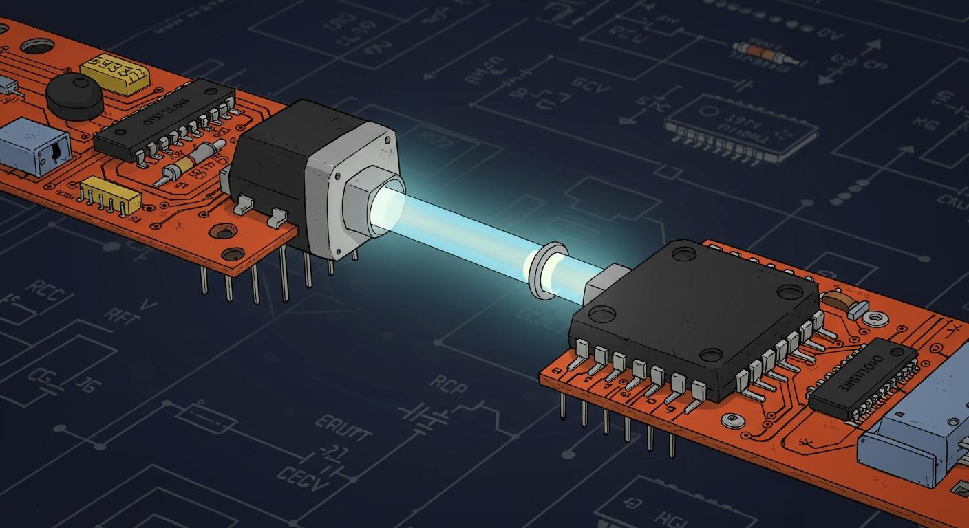
As engineers and designers, you face a major challenge: selecting the right optocoupler from thousands of available optocouplers. The global market for these optocouplers is projected to grow at a 7.5% rate, making this skill essential for any design.
This comprehensive guide is the practical guide you need. It is an optocouplers guide that simplifies choosing an optocoupler. You will master the fundamentals of opto coupling for complete isolation. This knowledge helps engineers and designers choose the best optocoupler, ensuring every optocoupler provides robust isolation. Engineers trust reliable optocouplers.
Key Takeaways
- Optocouplers create a safe electrical break between circuits. This protects sensitive parts from high voltages.
- The Current Transfer Ratio (CTR) shows how efficient an optocoupler is. It tells you how much output current you get from the input current.
- Always check the isolation voltage (VISO). This is the highest voltage the optocoupler can safely block.
- Match the optocoupler's output type to your circuit's needs. This ensures it can drive the load correctly.
- Consider how optocouplers age. Their performance can change over time, so plan for this in your design.
AN OPTOCOUPLERS GUIDE TO FUNDAMENTALS
This section of our optocouplers guide is your "optocouplers 101" foundation. You will learn how optocouplers achieve complete electrical isolation. Understanding these basics helps you appreciate how these small components protect your circuits and users.
THE CORE FUNCTION: GALVANIC ISOLATION
You use optocouplers to create galvanic isolation. This means you are making a complete break in the electrical connection between two circuits. This circuit isolation is crucial. It stops dangerous high voltages or electrical noise from crossing over and damaging sensitive components. For true safety, this isolation must meet strict international standards. These standards define the requirements for electrical isolation in equipment.
- UL 1577: This standard focuses on the safety of optical isolators. It defines the RMS voltage an optocoupler can handle for 60 seconds, known as VISO.
- IEC 60747: This standard sets requirements for basic and reinforced isolation. It defines the peak transient voltage (VIOTM) and surge voltage (VIOSM) an optocoupler must withstand.
THE PRINCIPLE OF OPTO COUPLING
The magic behind the isolation is opto coupling. An optocoupler converts an electrical signal into a light signal. It then sends this light across an internal gap. On the other side, a sensor converts the light back into an electrical signal. This process of opto coupling transfers information without any physical electrical path. This simple principle is what makes optocouplers so effective for signal isolation.
THE INTERNAL COMPONENTS
Every standard optocoupler contains two key parts packaged together:
- A light source, which is an infrared light-emitting diode (LED).
- A light sensor, which is a photosensitive semiconductor like a phototransistor.
These components are made from specific materials to work efficiently. The choice of material affects the optocoupler's performance.
| Component | Semiconductor Material |
|---|---|
| Light-Emitting Diode (LED) | Gallium Arsenide (GaAs) |
| Photodetector | Silicon |
THE ISOLATION BARRIER
A transparent insulating material physically separates the LED and the photodetector. This material forms the isolation barrier. Most optocouplers use a special polymer, like Polyimide (PI), to create this gap. This polymer is an excellent insulator and prevents any current from leaking across. The thickness and quality of this barrier determine the level of isolation the optocoupler provides.
Designer's Tip 📝: The integrity of this internal isolation barrier is the most critical factor for safety. It directly dictates the maximum voltage the optocoupler can safely block, ensuring robust electrical isolation. This is why understanding datasheet ratings for isolation is non-negotiable.
KEY PARAMETERS FOR OPTOCOUPLER SELECTION
You must understand a few key parameters to choose the right optocoupler. These values on the datasheet guide your selection. They ensure your design is both reliable and safe. Let's look at the most critical specifications for all optocouplers.
CURRENT TRANSFER RATIO (CTR)
The Current Transfer Ratio (CTR) is the most important specification for many optocouplers. It measures the efficiency of the optocoupler. Specifically, it tells you how much output current you get for a certain input current. You calculate it as a percentage.
CTR (%) = (Output Current / Input Current) × 100
A higher CTR means the optocoupler needs less input current to drive the output. The CTR of an optocoupler is not constant. It changes with temperature and the LED's forward current. This transfer ratio is a key factor in your circuit calculations.
ISOLATION VOLTAGE (VISO)
The isolation voltage (VISO) defines the maximum voltage the optocoupler can safely block. This rating is crucial for safety and circuit isolation. It ensures no dangerous voltage crosses the barrier. You must select an optocoupler with an isolation voltage that exceeds your application's requirements. A higher isolation voltage provides better protection. This isolation is the core function of all optocouplers.
BANDWIDTH AND PROPAGATION DELAY
Bandwidth determines how fast an optocoupler can transfer a signal. For slow DC signals, this is not a concern. For high-speed digital communication, it is vital. Standard optocouplers are slow, while high-speed optocouplers are much faster.
| Optocoupler Type | Typical Speed/Response Time |
|---|---|
| Standard Phototransistor | ~18 µs response time |
| High-speed Logic-Gate | 10 Mbps or more |
FORWARD CURRENT AND OUTPUT VOLTAGE
You must operate the optocoupler within its absolute maximum ratings. Two key limits are the LED forward current (IF) and the output transistor's collector-emitter voltage (VCEO). Exceeding these can destroy the optocoupler. For example, a popular 4N25 optocoupler has these limits:
| Rating | Value |
|---|---|
| Forward Current (IF) | 60 mA |
| Collector-Emitter Voltage (VCEO) | 70 V |
DATA SHEET DEGRADATION FACTORS
The performance of optocouplers degrades over time. The LED's light output decreases with use, which reduces the CTR. This aging effect is a critical factor for long-term reliability. Designers must account for this degradation to ensure the circuit works correctly over its entire lifespan. This is a key part of robust opto coupling design.
COMMON TYPES OF OPTOCOUPLERS
You will find several main types of optocouplers available for your designs. Each optocoupler is built for a specific purpose. Understanding these different types helps you select the perfect component for your circuit. The main types of optocouplers are defined by their output stage, which determines how they behave.
PHOTOTransistor OUTPUT
The phototransistor output is the most common and general-purpose type of optocoupler. You will see this optocoupler in many non-critical applications. However, you must be aware of its limitations.
- These optocouplers have slower response times, making them unsuitable for high-speed data.
- Their Current Transfer Ratio (CTR) can change with temperature and age, leading to inconsistent performance.
PHOTODARLINGTON OUTPUT
When you need a much higher CTR, you should choose a photodarlington optocoupler. These types of optocouplers provide significantly more output current for the same input current. A photodarlington optocoupler can have a CTR over 1000%. This is a huge increase compared to a standard phototransistor optocoupler, which might have a minimum CTR of only 20%.
PHOTO-TRIAC AND PHOTO-SCR OUTPUT
For controlling AC power, you need special optocouplers. Photo-TRIAC and Photo-SCR output optocouplers are designed for this job. These types allow a low-voltage DC signal to safely switch a high-voltage AC load. Zero-crossing detection is a feature in many of these optocouplers to reduce electrical noise. These are used in common optocoupler applications like lamp dimmers and motor speed controllers.
HIGH-SPEED LOGIC-GATE OUTPUT
When you need to isolate fast digital signals, standard optocouplers are too slow. You must use high-speed optocouplers. These components have a logic-gate output instead of a simple transistor. This design allows them to support fast data protocols. High-speed optocouplers are essential for isolating interfaces like SPI and CAN bus.
| Optocoupler Type | Maximum Data Rate (Mbps) | Minimum Pulse Width (ns) |
|---|---|---|
| Popular Industrial CMOS Optocoupler | 12.5 | 80 |
| Very High-Speed Optocoupler | N/A | 20 |
LINEAR OPTOCOUPLERS FOR ANALOG SIGNALS
Isolating an analog signal is tricky because you must maintain linearity. A linear optocoupler solves this problem with a clever design. It uses a feedback mechanism to ensure the output signal accurately follows the input.
- An internal LED is coupled with two photodiodes.
- One photodiode on the input side creates a feedback control signal.
- This signal acts as a servo, correcting for the LED's non-linear behavior.
- The second photodiode on the output then produces a linear signal.
SELECTING THE RIGHT OPTOCOUPLER: A 4-STEP PROCESS
You now understand the fundamentals and the different types available. This section is a practical guide to applying that knowledge. Selecting the right optocoupler does not have to be complicated. This four-step process will help you choose the perfect component for your design every time. Following this optocouplers guide ensures a safe and reliable circuit.
STEP 1: DEFINE ISOLATION REQUIREMENTS
Your first and most important step is safety. You must determine the level of electrical isolation your circuit needs. This starts with your system's working voltage. Safety standards like IEC 60950 use this voltage to define the minimum required spacing between the high and low voltage sides of the optocoupler.
Two key measurements for this spacing are:
- Creepage: The shortest distance along the surface of the insulating material.
- Clearance: The shortest distance through the air.
The required creepage distance depends on the working voltage, the pollution degree of the environment, and the insulator's material group. A higher pollution degree means more surface contamination, which requires greater creepage for safe isolation.
Designer's Tip 📝: For a given working voltage, higher pollution degrees demand greater creepage distances. You can sometimes use a component with a better material group (e.g., Group I instead of Group II) to reduce the required distance and allow for a smaller package.
The table below shows how these factors influence the required creepage for basic and reinforced isolation. Reinforced isolation offers a higher safety level, equivalent to two layers of basic isolation.
| Working Voltage Vrms | Pollution Degree | Material Group | Basic Insulation Creepage (mm) | Reinforced Insulation Creepage (mm) |
|---|---|---|---|---|
| 250 | 1 | I, II, III | 0.56 | 1.12 |
| 250 | 2 | I | 1.25 | 2.5 |
| 250 | 2 | II | 1.8 | 3.6 |
| 250 | 2 | III | 2.5 | 5.0 |
| 320 | 2 | I | 1.6 | 3.2 |
| 320 | 2 | II | 2.2 | 4.4 |
| 320 | 2 | III | 3.2 | 6.4 |
| 400 | 2 | I | 2.0 | 4.0 |
| 400 | 2 | II | 2.8 | 5.6 |
| 400 | 2 | III | 4.0 | 8.0 |
| 400 | 3 | I | 5.0 | 10.0 |
| 400 | 3 | II | 5.6 | 11.2 |
| 400 | 3 | III | 6.3 | 12.6 |
This chart visualizes how creepage requirements increase for a 400 Vrms system as the pollution degree worsens.
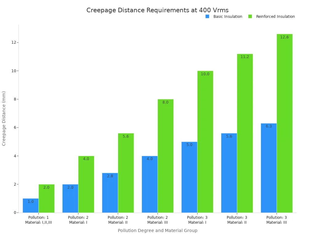
You must check the optocoupler datasheet to ensure its package provides the necessary creepage and clearance for your application's required isolation.
STEP 2: DETERMINE SIGNAL CHARACTERISTICS
Next, you need to analyze the signal you want to transfer. The characteristics of your signal will determine which type of optocoupler you need.
For digital communication, you must define two key things:
- Voltage Levels: These levels represent the binary states of 0 and 1. Common examples are 0V for logic 0 and 3.3V or 5V for logic 1.
- Data Rate: This is the speed of your signal, often measured in megabits per second (Mbps).
The data rate is critical. A faster data rate requires an optocoupler with a faster response time. The device's rise and fall times determine its ability to accurately track the input signal. For high-speed data transmission, a fast response time is often more important than any other specification. You must select an optocoupler with a bandwidth that can support your required data transfer rate to ensure reliable data isolation.
STEP 3: CALCULATE CTR AND DRIVE CURRENT
Now you must ensure the optocoupler will turn on correctly. You need to calculate the input current for the LED and confirm the output can provide enough current. This is where the Current Transfer Ratio (CTR) becomes essential.
First, you must calculate the value for the input current limiting resistor (R_F). This resistor protects the internal LED from drawing too much current. You can calculate it using Ohm's Law.
Here is a step-by-step calculation for a common scenario.
- Supply Voltage (Vs): 5V
- LED Forward Voltage (Vf): 1.2V (from the optocoupler datasheet)
- Target Forward Current (If): 10mA (0.010A)
// 1. Determine the voltage across the resistor.
Voltage across Resistor = Supply Voltage (Vs) - LED Forward Voltage (Vf)
3.8V = 5V - 1.2V

// 2. Apply Ohm's Law to find the resistance.
Resistor Value (R) = Voltage across Resistor / Target Forward Current (If)
380 Ohms = 3.8V / 0.010A
In this case, you would use a standard 380 Ohm resistor or the next closest standard value. After finding the input current, you use the CTR to find the output current. For example, if your optocoupler has a CTR of 50% and your input current is 10mA, your minimum output current will be 5mA. All designers must account for CTR degradation over the life of the optocouplers.
STEP 4: MATCH OUTPUT TYPE TO THE LOAD
Finally, you must match the optocoupler's output stage to the circuit it will be driving (the load). The output of the optocoupler needs to be compatible with the load's voltage and current requirements.
You can use the information from the "Common Types of Optocouplers" section to make your choice:
- Driving a logic input? A standard phototransistor output optocoupler is usually sufficient. It provides enough current to pull a microcontroller pin high or low.
- Driving a small relay or LED? You need more current. A photodarlington output optocoupler, with its very high CTR, is a great choice here.
- Switching an AC load like a lamp? You must use a photo-TRIAC or photo-SCR output optocoupler. These are specifically designed for AC control.
- Isolating a high-speed data line? Your only option is a high-speed logic-gate output optocoupler. A standard optocoupler is far too slow and will corrupt the data.
By matching the output type to your load, you complete the selection process. You will have chosen an optocoupler that is safe, fast enough for your signal, and powerful enough to drive your load. This methodical approach helps designers build robust and reliable systems.
APPLICATIONS AND DESIGN CONSIDERATIONS
You can use your knowledge in many real-world applications. This section explores common optocoupler applications and critical design pitfalls. Understanding these examples will improve your electronic design skills and help you build safer circuits.
APPLICATION: SMPS FEEDBACK LOOPS
You will often find an optocoupler in a Switched-Mode Power Supply (SMPS). It provides feedback from the high-voltage output side to the low-voltage control side. This feedback loop maintains stable output voltage while ensuring complete isolation. The popular PC817 is a great choice for these circuits.
// Simple SMPS Feedback Circuit
// High-Voltage Side          | Low-Voltage Side
//                            |
//   Output --[R1]--+-- Anode |
//                  |         | Optocoupler
//   Ref --[TL431]--+-- Cathode|
//                            |
//                            +-- Collector -- To MCU/PWM Controller
//                            |
//                            +-- Emitter ---- GND
Note 📝: The resistor values in this circuit design depend on the specific voltages and currents of your power supply.
APPLICATION: ISOLATING DIGITAL INTERFACES
Microcontroller I/O isolation is a key task for optocouplers. You can easily isolate simple signals like UART. However, bidirectional buses like I2C present a challenge. You can solve this by using multiple optocoupler channels. For example, you can use one optocoupler for the clock signal and two more for the separate send/receive data lines between your microcontroller and a peripheral. This is a common circuit design for microcontroller I/O isolation. These applications protect your microcontroller from voltage spikes.
APPLICATION: AC MAINS DETECTION
You can use an optocoupler to safely detect the presence of AC mains voltage. This is useful for a microcontroller to know when power is available. A bidirectional input optocoupler, like the H11AA1, simplifies these circuits. It contains two LEDs that work on both halves of the AC cycle. This allows your microcontroller to easily detect the AC signal. This is one of the most practical applications for an optocoupler.
PITFALL: IGNORING CTR AGING
An optocoupler's CTR degrades over its lifetime. You must account for this in your circuit design. If you design for the initial CTR, your circuit may fail years later. Always use the datasheet's end-of-life CTR value in your calculations. This ensures your circuits remain reliable.
PITFALL: INCORRECT INPUT RESISTOR
Choosing the wrong input resistor is a common mistake. A resistor value that is too low will destroy the internal LED. A value that is too high will not provide enough current to turn the optocoupler on. You must calculate the correct resistor value for your specific supply voltage and the LED's forward voltage. This simple step is vital for all applications.
PITFALL: OVERLOOKING TIMING SPECS
For high-speed applications, timing is everything. A slow optocoupler will corrupt your data. Always check the propagation delay, rise time, and fall time on the datasheet. These values must be fast enough for your signal's data rate.
For high-voltage circuits, you must also consider physical layout for electronic safety. Creepage (distance over a surface) and clearance (distance through air) are critical. Your board layout must meet the spacing requirements specified on the optocoupler datasheet to ensure robust isolation and pass safety certifications. This is a key part of a good design.
You now have a clear path for choosing the right optocoupler. Your 4-step framework simplifies the selection process for all your circuits. This careful method helps designers create reliable and robust isolated circuits.
Key Takeaway 📝: Always check these three critical parameters for every optocoupler to ensure your isolated circuits are safe.
- Isolation Voltage (VISO)
- Current Transfer Ratio (CTR)
- Bandwidth and Speed
FAQ
Can you use an optocoupler like a relay?
You can use an optocoupler to switch signals, similar to a relay. Optocouplers are solid-state devices, making them faster and more durable than mechanical relays. However, relays can typically handle much higher currents and voltages. Choose the component that best fits your load's power requirements.
How do you test an optocoupler?
You can test an optocoupler with a multimeter.
- Set your multimeter to the diode test mode to check the input LED.
- To test the output transistor, you can build a simple circuit. Apply a small current to the input and check if the output transistor switches on.
Why is isolation voltage so important?
Isolation voltage (VISO) is a critical safety rating. It tells you the maximum voltage the optocoupler can block between its input and output. You must select a VISO rating higher than any voltage in your system. This protects both users and sensitive electronics from dangerous electrical shocks.
What happens if the CTR is too low?
A low Current Transfer Ratio (CTR) means the optocoupler is inefficient. Your input signal may not create enough output current to drive your load. This can cause your circuit to work unreliably or fail completely. You should always calculate for the worst-case CTR value.