Recognizing and Interpreting Transformer Symbols in Today’s Electrical Diagrams
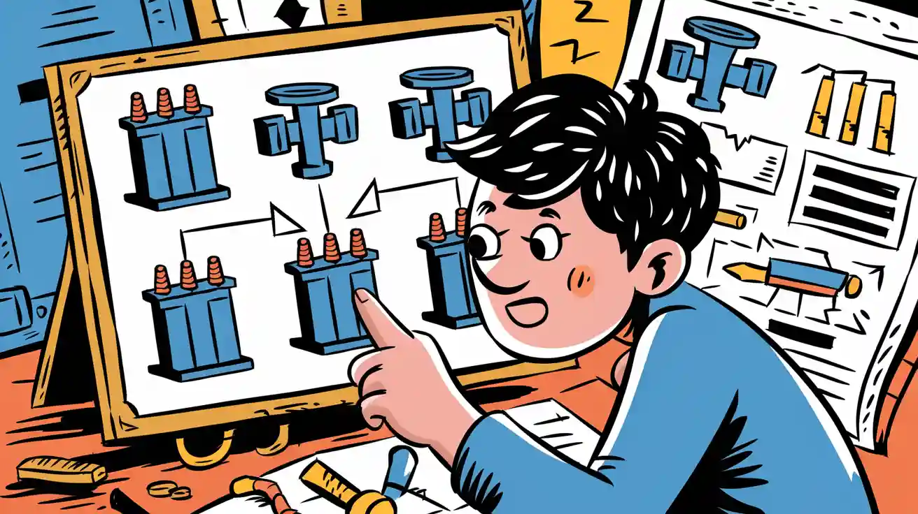
You often see electrical symbols in a schematic diagram. The transformer symbol shows you where a transformer sits in the diagram and how it works in the circuit. You use these electrical symbols to spot key parts like coils and the magnetic core. Each transformer symbol gives clear clues about the type of transformer and its function. Recognizing these electrical symbols helps you read a diagram safely and understand how each transformer affects the flow of electricity.
Key Takeaways
- Transformer symbols show key parts like windings, magnetic core, polarity dots, and terminal labels to help you understand how transformers work in a circuit.
- Different transformer types have unique symbols, such as single-phase with two coils, three-phase with three sets of windings, center-tapped, and autotransformers with special taps.
- Polarity dots indicate voltage and current direction; matching these dots when wiring keeps the circuit safe and working properly.
- Reading transformer winding diagrams carefully reveals coil connections, protection devices, feed types, and winding configurations like delta or wye.
- Avoid common mistakes by checking polarity dots, winding labels, core types, and tap changers; use reference guides and practice with real diagrams to improve your skills.
Transformer Symbol Identification
Basic Symbol Structure
When you look at a transformer symbol in a diagram, you see a simple but powerful picture. The most common transformer symbol shows two sets of lines or coils, often with a rectangle or two parallel lines between them. This rectangle or set of lines stands for the magnetic core. The coils on each side represent the windings. You often find letters or numbers next to the windings. These labels help you know which side is the input (primary) and which is the output (secondary).
Tip: Always check for a legend in the diagram. Some diagrams use ANSI standards, while others use IEC standards. ANSI transformer symbols appear more often in the United States. IEC symbols are popular worldwide and look more modern. Both types show the same parts, but the style can look different.
Here is a quick breakdown of what you might see in a basic transformer symbol:
- Two sets of curved or straight lines for the windings.
- A rectangle or two parallel lines for the core.
- Letters or numbers (like H1, X1) for winding terminals.
- Dots or marks for polarity.
You use these visual clues to spot the transformer in any electrical diagram.
Key Parts and Meanings
Each part of the transformer symbol tells you something important about how the transformer works in the circuit. You can use the table below to match each part with its meaning:
| Symbol Part | What It Shows | Why It Matters |
|---|---|---|
| Windings | Primary and secondary coils | These change the voltage up or down |
| Core | Magnetic path (rectangle or lines) | Helps transfer energy between windings |
| Polarity Dots | Small dots near windings | Show phase relationship and direction of current |
| Terminal Labels | Letters/numbers (H1, X1, etc.) | Identify input/output and help with wiring |
- Windings let you know where electricity enters and leaves the transformer.
- The core focuses the magnetic field, making the transformer work better.
- Polarity dots tell you if the voltages are in phase or out of phase. This helps you connect transformers safely.
- Terminal labels make sure you wire the transformer correctly.
You can find extra symbols in some diagrams, like tap changers or bushings. These show special features or connections.
Magnetic Core and Polarity
The magnetic core in a transformer symbol tells you about the type of transformer and its best use. If you see a rectangle or two solid lines, the transformer uses an iron core. Iron core transformers work well at low frequencies, like in power lines. If the symbol has no core or uses dashed lines, it might be an air core transformer. Air core transformers are good for high-frequency uses, such as radios. Sometimes, you see a symbol for a ferrite core, which works well in special circuits because it has low energy loss.
The core helps the transformer move energy from the primary to the secondary winding. Without a core, the magnetic field spreads out and the transformer does not work as well. With a core, the field stays focused, and the transformer works more efficiently.
Polarity is another key part of the transformer symbol. You see small dots or plus/minus signs near the windings. These marks show you which ends of the windings have the same voltage direction at the same time. If you connect transformers with the wrong polarity, you can cause errors in meters or even damage equipment. Always match the dots or polarity marks when wiring transformers in a circuit.
Note: Proper polarity keeps voltages and currents in phase. This is very important for safety and for making sure your circuit works as planned.
You can use these clues in the transformer symbol to understand how the transformer fits into the whole electrical diagram. By learning to spot each part, you make sure you read electrical symbols correctly and avoid mistakes.
Types of Transformer Symbols
Single-Phase Transformer Symbol
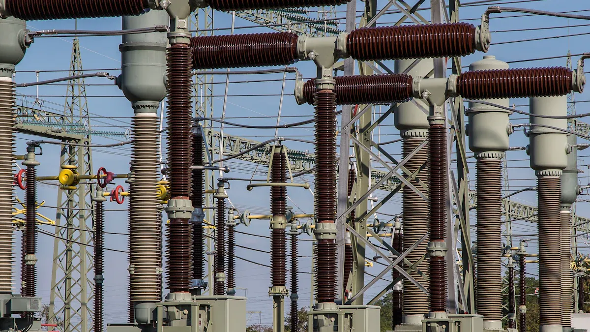
You often see the single-phase transformer in home and small business electrical systems. In a diagram, this transformer appears as two coils with a core between them. The primary winding connects to the input, and the secondary winding connects to the output. You may notice dots or polarity marks near the windings. These marks help you match the phase and direction of current. The single-phase transformer changes voltage levels for devices that use alternating current.
Three-Phase Transformer Symbol
Three-phase transformers work in larger power systems, such as factories or power plants. Their symbols look more complex in a diagram. You see three sets of windings, each labeled with letters like A, B, and C for the primary side, and a, b, and c for the secondary side. The way these windings connect tells you about the transformer's configuration. You can use the table below to understand the different connection types:
| Connection Type | Primary Winding Symbol | Secondary Winding Symbol |
|---|---|---|
| Star | Y | y |
| Delta | D | d |
| Interconnected Star | Z | z |
The combination of these symbols, such as Yy or Dd, shows how the windings connect inside the transformer. This affects how the transformer handles current and voltage in a three-phase system.
Tip: Always check the winding connection letters (Y, Δ) in the diagram. These letters tell you if the transformer uses a star (wye) or delta connection, which changes how the transformer works in the circuit.
Center-Tapped and Autotransformer Symbols
A center-tapped transformer has a special winding with a tap in the middle. In a diagram, you see an extra line coming from the center of the secondary winding. This tap lets you get two different voltages from one transformer. You often use this type in audio equipment or power supplies.
An autotransformer uses only one winding for both input and output. The symbol shows a single coil with taps at different points. This design saves space and material. You use autotransformers when you need to adjust voltage levels without full isolation.
Single Line Transformer Symbol
In large power systems, you may see a single line transformer symbol in a simplified diagram. This symbol gives you a quick view of the system. It does not show every wire or coil but highlights the main parts, such as the transformer, system voltage, and ratings. You use these diagrams to plan switching, find loads, and understand how power flows through the system. The single line diagram helps you see the big picture without getting lost in details.
Interpreting Transformer Symbols
Reading Transformer Winding Diagrams
You can learn a lot about a transformer by reading transformer winding diagrams. These diagrams show you how the coils connect inside the transformer. When you look at transformer winding diagrams, you should follow a step-by-step method to get all the important information:
- Find the Coil Connections: Look for the high voltage terminals, often labeled H1, H2, or H3. Then, find the low voltage terminals, usually marked X1, X2, X3, or X0. These labels help you see how the windings connect inside the transformer.
- Check for Protection Devices: Many diagrams include symbols for fuses or switches. For example, you might see a bayonet fuse labeled "BAY" or a load break switch marked "LBOR." These parts protect the transformer and help control its operation.
- Identify the Feed Type: Look at the bushing configuration. If you see six primary bushings, labeled H1A, H1B, and so on, you have a loop feed transformer. If you see only three bushings, labeled H1, H2, H3, you have a radial feed transformer. This tells you how the transformer connects to the power system.
- Analyze the Phasor Diagram: Some transformer winding diagrams include a phasor diagram. This shows the relationship between the primary and secondary windings. You can see if the transformer uses a delta or wye connection and if there is a phase shift.
- Look for Extra Features: Check the diagram and nameplate for details like electrostatic shields, impedance, temperature rise, cooling class, winding material, and bushing locations. These features tell you how the transformer will perform in real use.
Tip: Always read transformer winding diagrams carefully. Each symbol and label gives you clues about how the transformer works and how to connect it safely.
Dot Convention and Phase Relationships
The dot convention is a key part of transformer winding diagrams. You see small dots placed at one end of each winding in the diagram. These dots show you the phase relationship between the primary and secondary windings.
When you see dots at the same ends of both windings, the voltages and currents are in phase. This means that when the voltage at the dotted end of the primary winding rises, the voltage at the dotted end of the secondary winding rises too. The currents also flow in the same direction at the dotted ends. If the dots are at opposite ends, the voltages and currents are 180 degrees out of phase. In this case, when the voltage at the dotted end of the primary winding rises, the voltage at the dotted end of the secondary winding falls.
You can think of the dot convention as a way to mark the polarity of the windings. If you connect the transformer with the dots matched, you keep the voltages in phase. If you connect the transformer with the dots mismatched, you create a phase shift. This can cause problems in your circuit, such as phase cancellation or incorrect relay operation.
Note: Always pay attention to the dot convention in transformer winding diagrams. It helps you avoid wiring mistakes and keeps your circuit working as planned.
Winding Connections and Notations
Winding connections and notations in transformer winding diagrams tell you how the windings join together. You often see symbols and letters that show the type of connection. The most common types are delta (Δ) and wye (Y or star).
- Delta Connection (Δ): The windings connect in a triangle shape. Each corner of the triangle connects to a phase. This setup works well for heavy loads and gives a stable voltage.
- Wye Connection (Y): The windings connect in a "Y" shape. One end of each winding joins at a common point, called the neutral. The other ends connect to the phases. This setup is common in power distribution.
You also see notations like Yy, Dy, or Dd in transformer winding diagrams. The first letter shows the primary winding connection, and the second letter shows the secondary winding connection. For example, "Dy" means the primary winding is delta, and the secondary winding is wye.
| Notation | Primary Connection | Secondary Connection |
|---|---|---|
| Yy | Wye | Wye |
| Dd | Delta | Delta |
| Dy | Delta | Wye |
You should always check these notations in the diagram. They tell you how the transformer will handle voltage and current. They also help you match the transformer to the rest of your system.
Tip: Understanding winding connections in transformer winding diagrams helps you choose the right transformer for your needs and connect it safely.
Common Mistakes and Tips
Misreading Symbol Parts
You might find transformer symbols confusing at first. Many people make mistakes when they look at these symbols in electrical diagrams. Here are some common errors you should watch out for:
- Ignoring Polarity Dots: You may miss the small dots that show polarity. If you skip these, you can wire the transformer incorrectly.
- Mixing Up Windings: Sometimes, you might not notice which winding is primary and which is secondary. This can lead to wrong connections.
- Overlooking Core Types: You may not see if the symbol shows an iron core, air core, or ferrite core. Each type works best in different circuits.
- Missing Tap Changers: Some symbols have extra lines for tap changers. If you ignore these, you might not use the transformer’s full features.
- Confusing Connection Letters: Letters like Y, Δ, or Z show how windings connect. If you mix these up, you can misunderstand the circuit.
Note: Always take your time to study each part of the symbol. Rushing can lead to mistakes that affect safety and performance.
Tips for Accurate Recognition
You can improve your skills in reading transformer symbols by following some simple steps. Try these tips to avoid mistakes and read diagrams with confidence:
- Use a Reference Guide: Keep a chart or table of standard transformer symbols nearby. This helps you check your work.
- Check the Legend: Most diagrams include a legend. Use it to match symbols and understand special markings.
- Look for Labels: Pay attention to terminal labels like H1, X1, or tap numbers. These guide you in wiring and troubleshooting.
- Practice with Real Diagrams: The more diagrams you read, the better you get. Start with simple ones and move to complex systems.
- Ask Questions: If you feel unsure, ask a teacher or a skilled electrician. Learning from others helps you avoid common errors.
| Mistake Type | How to Avoid It |
|---|---|
| Missing polarity | Always look for dots |
| Wrong winding | Check labels and positions |
| Ignoring core type | Notice the core symbol style |
| Skipping tap changers | Watch for extra lines or taps |
Tip: Practice makes perfect. The more you work with transformer symbols, the easier it becomes to spot details and avoid errors.
You now know how to spot and understand transformer symbols in electrical diagrams. Paying attention to details like windings, cores, and polarity helps you read circuits safely. Always check diagrams against trusted standards. The IEEE and ANSI publish widely recognized guidelines for transformer symbols, making their standards a reliable reference.
Keep practicing with real diagrams. You build confidence and accuracy each time you review symbols. For deeper learning, explore resources from IEEE, ANSI, or IEC.
FAQ
What does the dot on a transformer symbol mean?
The dot shows you the polarity of the windings. When the voltage rises at the dotted end of the primary, it rises at the dotted end of the secondary. This helps you connect transformers correctly.
How can you tell if a transformer is single-phase or three-phase in a diagram?
You see two windings for single-phase transformers. Three-phase transformers show three sets of windings, often labeled A, B, C. The symbol style makes it easy to spot the difference.
Why do some transformer symbols have extra lines or taps?
Extra lines or taps show special features like center taps or tap changers. These let you get different voltages from one transformer. Always check the diagram legend for details.
What do the letters Y and Δ mean in transformer symbols?
Y stands for wye (star) connection. Δ stands for delta connection. These letters tell you how the windings connect inside the transformer. The connection type affects voltage and current flow.
Can you use the same symbol for all transformer types?
No, you cannot. Each transformer type has a unique symbol. Using the correct symbol helps you avoid confusion and ensures safe wiring.