Top 5 Beginner 74hc595 Projects for 2025
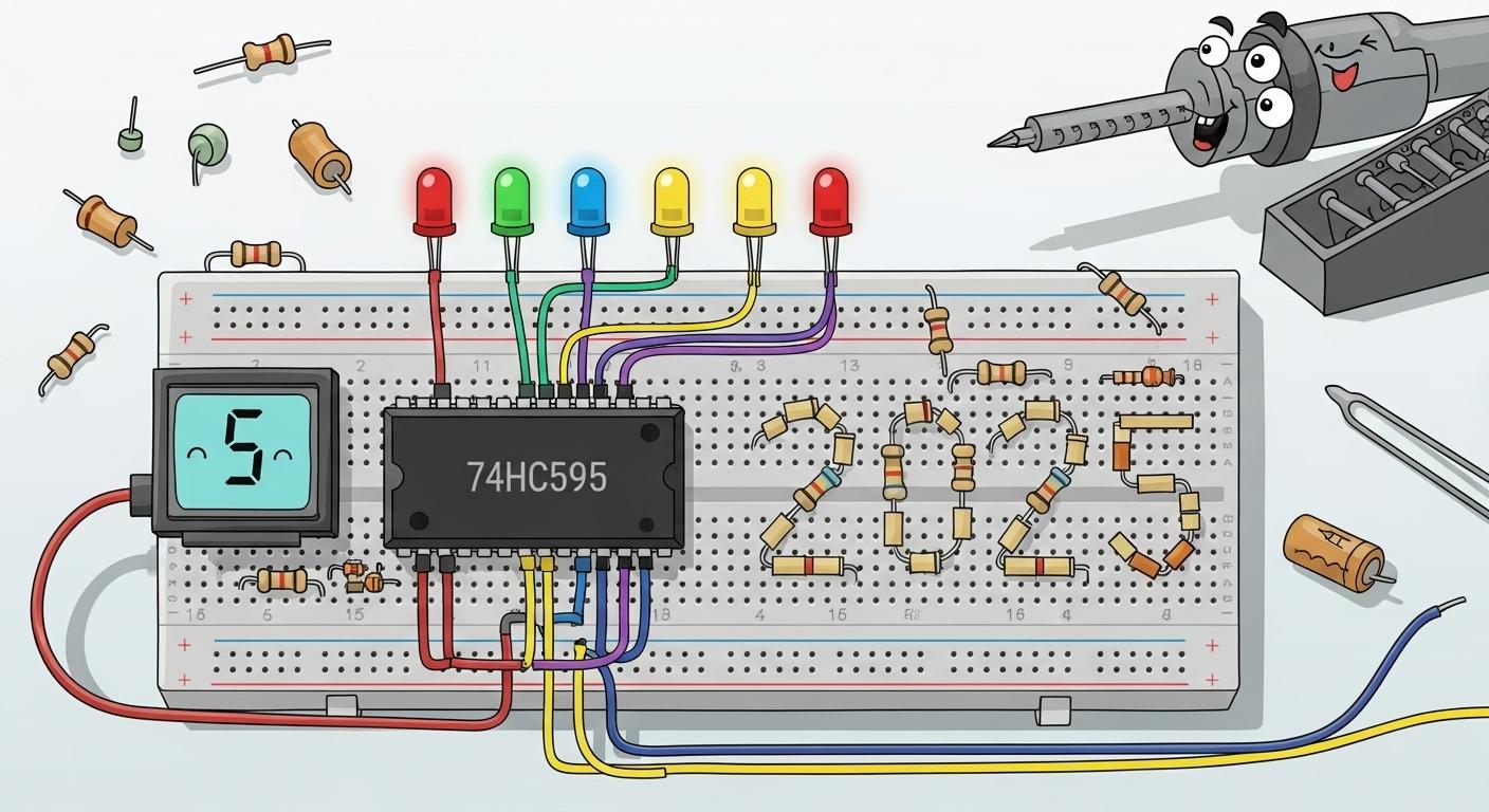
You are ready to build exciting projects with the 74hc595 shift register. Below are five great projects to get you started. Projects like driving a 7-segment display are very popular, as seen in recent tutorials. The market for these components continues to grow.
Attribute | Details |
|---|---|
5.1% | |
Forecast Period | 2025 - 2035 |
Here is a preview of what you can build:
Build an LED Chaser with the 74hc595
Drive a 7-Segment Display with a Register
Control an 8x8 LED Matrix
Expand Your Arduino with a Shift Register
Mix Colors with RGB Shift Registers
Ready to start? Each guide gives you a component list, a simple explanation of how the circuit works, and the complete code for your LED project.
Key Takeaways
The 74hc595 shift register helps you control many things with few Arduino pins.
You can build cool projects like LED chasers and number displays with this chip.
Connecting multiple 74hc595 chips together lets you control even more lights or parts.
Always use a separate power supply for big projects to keep your Arduino safe.
Build an LED Chaser with the 74hc595
This project is a perfect introduction to the world of shift registers. You will learn to control eight individual LEDs using only three pins from your microcontroller. This skill is the foundation for building more advanced displays and interfaces.
Required Components
You will need a few common electronic parts to get started. You can find these components at most online electronics stores.
Item | Quantity | Notes |
|---|---|---|
Arduino UNO (or similar) | 1 | The brain of our project. |
74hc595 Shift Register | 1 | Prices are often around $3.60 per unit. |
Standard LED | 8 | Any color will work. |
330Ω Resistor | 8 | Protects your LEDs from too much current. |
Breadboard | 1 | For building the circuit without soldering. |
Jumper Wires | Several | To connect everything. |
LED Tip: A standard LED shines brightly at 20mA of current. Using a 330 Ohm resistor is a safe and effective choice for most projects.
How It Works
The 74hc595 chip is a serial-to-parallel converter. You send it data one bit at a time (serially), and it provides that data on eight separate pins at once (in parallel).
Your microcontroller sends a byte (8 bits) of data to the SER (Serial Data) pin. Each time the SRCLK (Shift Register Clock) pin pulses, the chip reads one bit. After eight pulses, the entire byte is inside the shift register. Then, you pulse the RCLK (Storage Register Clock) pin. This action "latches" the data, sending it to the Q0-Q7 output pins and turning the corresponding LED lights on or off. This process allows you to control eight LEDs with just a few control lines.
Circuit and Code
You will connect the 74hc595 to your Arduino and the eight LEDs to its output pins. Each LED needs its own 330Ω resistor connected to ground.
This simple Arduino code creates a "chasing" effect where one LED lights up at a time, moving down the line. The shiftOut() function makes it easy to send data to the register.
// Arduino Pin connected to ST_CP of 74HC595
int latchPin = 8;
// Arduino Pin connected to SH_CP of 74HC595
int clockPin = 12;
// Arduino Pin connected to DS of 74HC595
int dataPin = 11;

void setup() {
  // Set pins to output
  pinMode(latchPin, OUTPUT);
  pinMode(clockPin, OUTPUT);
  pinMode(dataPin, OUTPUT);
}

void loop() {
  // Loop to light up one LED at a time
  for (int i = 0; i < 8; i++) {
    // The byte to send, with only one bit set to HIGH
    byte led_state = 1 << i;

    // Ground the latchPin and send the data
    digitalWrite(latchPin, LOW);
    shiftOut(dataPin, clockPin, MSBFIRST, led_state);

    // Pull the latchPin high to display the data
    digitalWrite(latchPin, HIGH);
    delay(100); // Wait for 100ms
  }
}
Drive a 7-Segment Display with a Register
You can easily create a number counter or a simple clock with a 7-segment display. This project teaches you how to control this common component using your shift register, saving valuable microcontroller pins. You will learn to send specific data patterns to show numbers on the display.
Required Components
You will need the following parts for this project. This guide uses a common cathode display.
Item | Quantity | Notes |
|---|---|---|
Arduino UNO (or similar) | 1 | Controls the shift register. |
74hc595 Shift Register | 1 | Sends data to the display. |
1 | Common Cathode type. | |
220Ω Resistor | 8 | One for each segment. |
Breadboard | 1 | For your circuit. |
Jumper Wires | Several | To make connections. |
How It Works
A 7-segment display has seven LEDs (segments) arranged in a figure-eight pattern. You turn specific segments on to form numbers. There are two main types of 7-segment displays.
Feature | Common Anode Display | Common Cathode Display |
|---|---|---|
LED Connection | All LED anodes connected together | All LED cathodes connected together |
Driver Output | Outputs become low to turn each segment on | Outputs become high to turn each segment on |
You will connect the 74hc595's output pins, Q0 to Q7, to the display segments. These pins correspond to segments A through G and the decimal point (DP). To show a number, you send a specific byte to the register. Each bit in the byte controls one segment. For example, to display the number "1", you only need to light up segments B and C.
The table below shows the binary pattern needed for each digit on a common cathode display.
Decimal Digit | Hexadecimal Code | Binary Representation (gfedcba) |
|---|---|---|
0 | 0x3F | 0111111 |
1 | 0x06 | 0000110 |
2 | 0x5B | 1011011 |
3 | 0x4F | 1001111 |
4 | 0x66 | 1100110 |
5 | 0x6D | 1101101 |
6 | 0x7D | 1111101 |
7 | 0x07 | 0000111 |
8 | 0x7F | 1111111 |
9 | 0x67 | 1100111 |
Circuit and Code
Assemble the circuit by connecting the Arduino to the 74hc595 and the shift register's outputs to the 7-segment display through the resistors. The following chart visualizes the values you will send to the display.
This Arduino code uses an array to hold the byte patterns. It loops through the array, sending each pattern to the shift register to count from 0 to 9 on the display.
// Pin connections
int latchPin = 8;
int clockPin = 12;
int dataPin = 11;

// Hex codes for digits 0-9 (Common Cathode)
byte digit_patterns[10] = {
  0x3F, 0x06, 0x5B, 0x4F, 0x66, 0x6D, 0x7D, 0x07, 0x7F, 0x67
};

void setup() {
  pinMode(latchPin, OUTPUT);
  pinMode(clockPin, OUTPUT);
  pinMode(dataPin, OUTPUT);
}

void loop() {
  // Loop through each digit
  for (int i = 0; i < 10; i++) {
    // Send the digit pattern to the shift register
    digitalWrite(latchPin, LOW);
    shiftOut(dataPin, clockPin, MSBFIRST, digit_patterns[i]);
    digitalWrite(latchPin, HIGH);
    delay(500); // Wait for half a second
  }
}
Control an 8x8 LED Matrix
This led matrix project takes your skills to the next level. You will move from controlling a single line of lights to creating patterns and animations on a 64-LED grid. An 8x8 led matrix display offers a fantastic canvas for simple graphics. You will learn to control all 64 LEDs while still using just three Arduino pins.
Required Components
For this project, you will need two shift registers to manage the 16 connections of the matrix.
Item | Quantity | Notes |
|---|---|---|
Arduino UNO (or similar) | 1 | The project controller. |
74hc595 Shift Register | 2 | We will link these together. |
8x8 LED Matrix | 1 | Common Cathode type is used here. |
220Ω Resistor | 8 | For the row or column connections. |
Breadboard | 1 | A large one is recommended. |
Jumper Wires | Several | To connect the components. |
Power Tip: A single 8x8 led matrix display can use a lot of power. If every led is on at full brightness, the matrix could draw over 2 Amperes. For a bright display, you should use a separate 5V 2A power supply to avoid damaging your Arduino.
How It Works
An 8x8 led matrix display has 64 individual LEDs arranged in a grid. The matrix has 16 pins: eight for the rows and eight for the columns. To control 16 lines, you need more than the eight outputs from a single 74hc595. The solution is to daisy-chain two shift registers together.
You connect the QH' (serial output) pin of the first register to the SER (serial data) pin of the second. Both registers share the same clock and latch pins. This setup creates a single 16-bit register. When you shift data, the first 8 bits go into the second register, and the next 8 bits fill the first one.
You cannot light every led on the matrix at once. Instead, you use a technique called scanning.
You send 16 bits of data to the registers. 8 bits select a single row to power on, and 8 bits select which LEDs in that row should light up.
You latch the data to the output pins.
You repeat this process for the next row very quickly.
Your eyes' persistence of vision blends the rapidly flashing rows into a complete, stable image on the display. This is how all led display modules, from a small matrix to a large 8x40 led matrix, create images. This method lets you control the entire led matrix display.
Circuit and Code
You will connect your Arduino's three control pins to the first shift register. Then, you will connect the first register to the second. Finally, you will wire the 16 outputs from the two registers to the 8 row and 8 column pins of the led matrix.
The code below shows how to send 16 bits of data to the daisy-chained registers. We will send two bytes in a row. The shiftOut() function is called twice before you toggle the latch pin. This first shiftOut pushes data to the second register, and the second shiftOut fills the first register. This code will create a simple 'X' pattern on the display. The full code for a scanning display is more complex, but this shows the core data-sending process for the matrix.
// Pin connections to the first 74HC595
int latchPin = 8;
int clockPin = 12;
int dataPin = 11;

// 16-bit pattern for the letter 'X'
byte row_data = 0b10000001; // Data for the rows
byte col_data = 0b10000001; // Data for the columns

void setup() {
  pinMode(latchPin, OUTPUT);
  pinMode(clockPin, OUTPUT);
  pinMode(dataPin, OUTPUT);
}

void loop() {
  // Latch low to begin sending data
  digitalWrite(latchPin, LOW);

  // Shift out the 16 bits of data
  // This data goes to the SECOND shift register (controlling columns)
  shiftOut(dataPin, clockPin, MSBFIRST, col_data);
  // This data goes to the FIRST shift register (controlling rows)
  shiftOut(dataPin, clockPin, MSBFIRST, row_data);

  // Latch high to display the data on the LEDs
  digitalWrite(latchPin, HIGH);
}
This is a foundational skill for any project using an 8x40 led matrix or other large led display modules. You now have a powerful way to create a visual display.
Expand Your Arduino with a Shift Register
Your Arduino has a limited number of digital pins. This project shows you a practical way to solve that problem. You will learn to use a 74hc595 to add eight new digital output pins to your microcontroller. This powerful technique uses only three of your Arduino pins. These new outputs are not just for LEDs. You can also control other components, including:
Relays
Other integrated circuits
Required Components
You will need the same basic parts from the first project to give your Arduino more outputs.
Item | Quantity | Notes |
|---|---|---|
Arduino UNO (or similar) | 1 | The main controller. |
74hc595 Shift Register | 1 | Your port expander. |
Breadboard | 1 | For building the circuit. |
Jumper Wires | Several | To connect everything. |
Output Components | Up to 8 | LEDs, small motors with transistors, etc. |
How It Works
This project turns your 74hc595 into a simple output expander. You are essentially creating eight new "virtual" pins for your microcontroller. The core idea is to send a single byte (a number from 0 to 255) to the shift register. Each bit in that byte corresponds to one of the eight output pins, turning it either HIGH or LOW. This allows you to set the state of all eight pins at once with a single command.
Shift Registers vs. I2C Expanders The 74hc595 is a simple and cheap way to get more outputs. Other chips, like the PCF8574, use a different system called I2C. I2C expanders are more flexible because their pins can be used for both input and output, but they are also more expensive. For projects that only need more outputs, shift registers are a perfect choice.
To update the outputs, you will shift a new byte of data into the register. This process is very fast and gives your Arduino control over many more components.
Circuit and Code
The circuit is identical to the LED Chaser project. You connect the three control pins from the Arduino to the data, clock, and latch pins of the 74hc595. Then, you connect your chosen components to the Q0-Q7 output pins.
This example code creates a simple function, updateOutputs(), to make the process easy. You can call this function anytime you want to change the state of your eight new pins. The code demonstrates turning different patterns on and off.
// Pin connections
int latchPin = 8;
int clockPin = 12;
int dataPin = 11;

void setup() {
  pinMode(latchPin, OUTPUT);
  pinMode(clockPin, OUTPUT);
  pinMode(dataPin, OUTPUT);
}

// A function to easily update the shift register
void updateOutputs(byte data) {
  digitalWrite(latchPin, LOW);
  shiftOut(dataPin, clockPin, MSBFIRST, data);
  digitalWrite(latchPin, HIGH);
}

void loop() {
  // Turn on first four outputs (0b00001111)
  updateOutputs(15);
  delay(1000);

  // Turn on last four outputs (0b11110000)
  updateOutputs(240);
  delay(1000);
}
Mix Colors with RGB Shift Registers
This project combines your skills to create a vibrant light show. You will learn to control RGB LEDs to mix and display a wide spectrum of colors. An RGB LED is like three separate LEDs (Red, Green, and Blue) in a single package. By controlling the brightness of each, you can create almost any color you can imagine. This is a fun way to add dynamic lighting to your projects.
Required Components
You will need a few parts to start mixing colors. This guide uses common cathode RGB LEDs.
Item | Quantity | Notes |
|---|---|---|
Arduino UNO (or similar) | 1 | The project's brain. |
74hc595 Shift Register | 1 | Controls the RGB LEDs. |
RGB LED (Common Cathode) | 2 | You can control two with one register. |
220Ω Resistor | 6 | One for each color pin on each LED. |
Breadboard | 1 | For building the circuit. |
Jumper Wires | Several | To connect everything. |
How It Works
An RGB LED has four pins: one for each color (Red, Green, Blue) and one common pin (in our case, a cathode connected to ground). To control one RGB LED, you need three output pins. Your 74hc595 has eight outputs, so you can control two RGB LEDs completely, with two outputs to spare. You will shift data to the register to turn each color of each LED on or off.
You can add one or two more shift registers very easily. This lets you maximize your output to control a 16 or even 24-channel light display or a small RGB matrix. You just link Pin 9 of the first register to the data pin of the second one.
A key challenge is power. Your Arduino cannot provide enough power for many bright LEDs. You will need an external power source for a project with multiple LEDs. It is also very important to give each color pin on every single LED its own resistor. Do not share one resistor for all the red pins, for example. This ensures each LED gets the correct current.
Circuit and Code
Connect your Arduino to the shift register. Then, connect the first six output pins of the register to the R, G, and B pins of your two RGB LEDs. Remember to use a resistor for each connection.
This code will cycle through red, green, and blue on both LEDs. You shift a byte of data to the register to set the colors. For example, the byte 0b00100001 turns on the red pin of the first LED (bit 0) and the red pin of the second LED (bit 5). This is a great foundation for building a larger light matrix.
// Pin connections
int latchPin = 8;
int clockPin = 12;
int dataPin = 11;

// LED 1: Q0(R), Q1(G), Q2(B)
// LED 2: Q3(R), Q4(G), Q5(B)

void setup() {
  pinMode(latchPin, OUTPUT);
  pinMode(clockPin, OUTPUT);
  pinMode(dataPin, OUTPUT);
}

void loop() {
  // Turn on RED
  shiftData(0b00001001);
  delay(500);

  // Turn on GREEN
  shiftData(0b00010010);
  delay(500);

  // Turn on BLUE
  shiftData(0b00100100);
  delay(500);
}

// Function to send data to the register
void shiftData(byte data) {
  digitalWrite(latchPin, LOW);
  shiftOut(dataPin, clockPin, MSBFIRST, data);
  digitalWrite(latchPin, HIGH);
}
You have seen how the 74hc595 can build an LED chaser, run a 7-segment display, and even control a full matrix. Each project shows how this simple shift register expands your microcontroller. Mastering this single output component lets you shift from basic lights to a more complex display. The 74hc595 is a key part for any maker wanting to control more with their microcontroller.
Ready to build? 🚀 Pick your favorite project and get started! If you run into any issues or want to show off your creation, share it in the comments below.
FAQ
How many 74hc595s can you connect together?
You can connect many shift registers in a series. This technique is called "daisy-chaining". Each new chip adds eight more outputs. You just connect the serial out pin (QH') of one chip to the serial data pin (SER) of the next one.
Why do the pin names look different on my chip?
Different manufacturers use different labels for the pins. You might see DS instead of SER for the data pin. The function is the same.
Always check your component's datasheet. The datasheet is the best source of truth for pin functions and names.
What does the Output Enable (OE) pin do?
The OE pin turns all outputs on or off at once. You connect it to ground to enable the outputs. You can also connect it to a microcontroller pin. This lets you control the brightness of your LEDs using PWM (Pulse Width Modulation).
Can I power my project from the Arduino?
Your Arduino provides limited power. It is great for a few LEDs. For larger projects like an 8x8 matrix, you need an external power supply. This prevents damage to your Arduino and ensures your LEDs are bright.