10 Simple LDR Circuits for Aspiring Engineers
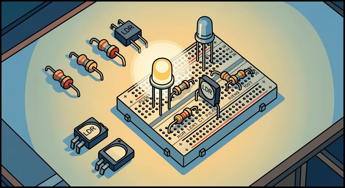
A light dependent resistor is a component whose resistance changes with light. You can use this simple LDR in many electronic circuit projects, from street light automation to robotics. The global market for the LDR is projected to grow, showing how vital this LDR is for light detection.
Ready to build? 💡 Here are ten simple LDR circuit projects you can start today. These projects will guide you through creating a functional circuit.
Automatic Night Lamp
Simple Light Meter Circuit
Dark-Activated Buzzer Alarm
Light-Controlled LED Dimmer
Shadow Detector Circuit
Simple Line Follower Sensor Circuit
Light-Activated Relay Switch
Fridge Door Alarm Projects
Light-Controlled Oscillator Projects
Simple Laser Tripwire Alarm Projects
Key Takeaways
An LDR changes its resistance based on light. It has high resistance in the dark and low resistance in bright light.
You can use an LDR with a voltage divider to create a changing voltage signal. This signal can control other parts of a circuit.
A transistor acts like a switch. It turns on or off based on the voltage from the LDR circuit.
LDR circuits can automate tasks. Examples include turning on lights at night or sounding an alarm in the dark.
You can build many projects with LDRs. These projects help you learn about electronics.
Understanding the Light Dependent Resistor (LDR)
Before you build your first circuit, you need to understand how a light dependent resistor works. An LDR is a special type of resistor. Its resistance changes based on the amount of light that hits it. This simple component is key to many light detection circuits.
The Principle of Photoconductivity
An LDR works because of a property called photoconductivity. The most common material used in light dependent resistors is Cadmium Sulfide (CdS). This material is a semiconductor. When light photons strike the LDR, they give electrons energy. This energy allows the electrons to move more freely, which lowers the LDR's resistance. In the dark, the LDR has very few free electrons, so its resistance is very high. The spectral response of a CdS LDR is very similar to the human eye, making it perfect for projects that react to visible light.
LDR Resistance Changes The resistance of an LDR changes dramatically. You can see the typical values below.
Light Condition | Resistance Range |
|---|---|
Bright Light | 100Ω to 500Ω |
Complete Darkness | 1MΩ (1,000,000Ω) or more |
Simple Electronic Circuit: The LDR Voltage Divider
You can turn the LDR's changing resistance into a useful voltage signal. You do this with a voltage divider circuit. This circuit uses two resistors to divide the source voltage. You can build this simple circuit by connecting your LDR in series with a fixed resistor. As light levels change, the resistance of the LDR changes. This change alters the voltage at the point between the two resistors. This changing voltage is your output signal.
You can calculate the output voltage (Vout) of this circuit with the following formula, where the LDR is either R1 or R2:
Vout = Vin * (R2 / (R1 + R2))
Using a Transistor as a Switch
A transistor can act as an electronic switch in your circuit. It uses a small voltage or current at its base to control a much larger current flowing through its collector and emitter. You can connect the output voltage from your LDR voltage divider circuit to the base of a transistor. When it gets dark, the LDR's resistance increases. This can raise the voltage at the transistor's base.
When the base voltage is below about 0.6V, the transistor is OFF.
When the base voltage rises above 0.7V, the transistor turns ON.
Once the transistor is on, it allows current to flow and power another part of the circuit, like an LED or a buzzer. This is how your LDR circuit can control other components.
10 Simple LDR Circuit Projects
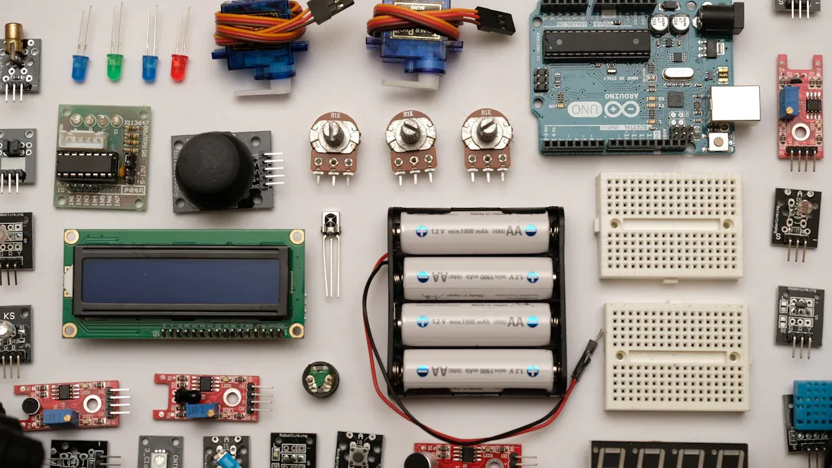
Now you are ready to build! The following ten simple LDR circuit projects will help you apply your knowledge. Each circuit provides a hands-on way to understand fundamental electronics.
1. Automatic Night Light
Objective: This circuit automatically turns on an LED when the room gets dark.
Components Needed:
1 x LDR
1 x 10kΩ Resistor
1 x BC547 NPN Transistor
1 x White LED
1 x 9V Battery and Clip
How It Works: You will build a voltage divider with the LDR and the 10kΩ resistor. During the day, the LDR has low resistance, so the voltage at the transistor's base is low. This keeps the transistor OFF, and the LED does not light up. When darkness falls, the LDR's resistance increases significantly. This raises the base voltage, turning the transistor ON. The transistor then allows current to flow from the battery through the LED, causing it to glow. This automatic night lamp circuit is a classic beginner project.
Learning Outcome: This circuit demonstrates how to use a transistor as a light-activated switch.
2. Simple Light Meter
Objective: This circuit uses a multimeter to measure light intensity by reading a changing voltage.
Components Needed:
1 x LDR
1 x 10kΩ Resistor
1 x 9V Battery and Clip
1 x Multimeter
How It Works: You will create a simple voltage divider circuit. Connect the LDR and the 10kΩ resistor in series across the 9V battery. Then, set your multimeter to measure DC voltage. Connect the multimeter's probes to the point between the LDR and the resistor. As you expose the LDR to different light levels, its resistance changes. This change alters the voltage division, and you will see the voltage reading on your multimeter change accordingly. A higher voltage indicates more light.
Learning Outcome: This project provides a practical application of the voltage divider principle.
3. Dark-Activated Buzzer Alarm
Objective: This circuit sounds a buzzer when it detects darkness, acting as a simple security alarm.
Components Needed:
1 x LDR
1 x 10kΩ Resistor
1 x BC547 NPN Transistor
1 x Piezo Buzzer
1 x 9V Battery and Clip
How It Works: This circuit is very similar to the automatic night light. You replace the LED with a piezo buzzer. The LDR and resistor form a voltage divider that controls the transistor. In the light, the transistor is OFF, and the buzzer is silent. When a shadow falls on the LDR or the lights go out, the LDR's resistance rises. This turns the transistor ON, completing the circuit for the buzzer. The buzzer then emits a sound, alerting you to the change.
Real-World Security 🚨 Commercial security systems use this same principle. For example, some systems use sensors to detect a breach in a dark area, triggering powerful sirens and floodlights to scare away intruders. This simple circuit is the foundation for more advanced security electronic circuit projects.
Learning Outcome: This circuit teaches you how to trigger an audible output using a transistor as a switch.
4. Light-Controlled LED Dimmer
Objective: This circuit allows you to smoothly dim an LED by changing the light level on the LDR.
Components Needed:
1 x LDR
1 x 100kΩ Potentiometer
1 x 10µF Capacitor
1 x BC547 NPN Transistor
1 x LED
1 x 330Ω Resistor
1 x 9V Battery and Clip
How It Works: In this circuit, the LDR and potentiometer control the charging and discharging rate of the capacitor. This capacitor is connected to the base of the transistor. When the LDR is in bright light, the capacitor charges slowly, providing less current to the transistor's base, which makes the LED dim. In darkness, the LDR's high resistance allows the capacitor to charge more quickly, turning the transistor on more strongly and making the LED brighter. You can adjust the sensitivity with the potentiometer.
Experiment with Fading! The capacitor's value directly controls the fade-in and fade-out speed of the LED. If you increase the capacitor's value, you will notice a slower, more gradual dimming effect. Using a smaller capacitor will make the dimming action much faster.
Learning Outcome: This circuit introduces the concept of using a capacitor and transistor together to create an analog dimming effect instead of simple on/off switching. These types of circuit projects are great for learning analog control.
5. Shadow Detector
Objective: This sensitive circuit detects a passing shadow and triggers an output.
Components Needed:
1 x LDR
1 x 1MΩ Potentiometer
1 x LM358 Op-Amp
1 x LED
1 x 330Ω Resistor
1 x 5V Power Supply
How It Works: This circuit uses an LM358 operational amplifier (op-amp) as a comparator. You create two voltage dividers. One uses the LDR, and the other uses the potentiometer to set a reference voltage. The op-amp compares the voltage from the LDR to the reference voltage. Normally, the light on the LDR keeps its voltage above the reference. When a shadow passes over the LDR, its resistance increases, and its voltage drops below the reference. This change causes the op-amp's output to switch, turning on the LED. You can adjust the potentiometer to make the circuit more or less sensitive to shadows.
Learning Outcome: This circuit demonstrates how to use an op-amp as a comparator to detect small changes in voltage.
6. Simple Line Follower Sensor
Objective: This circuit creates a basic sensor that can distinguish between a black line and a white surface for a robot.
Components Needed:
2 x LDRs
2 x 10kΩ Resistors
2 x White LEDs (to illuminate the surface)
A small protoboard
How It Works: You will build two identical voltage divider circuits, one for each LDR. Mount the LDRs and white LEDs side-by-side, pointing downwards. The LEDs illuminate the surface below. When an LDR is over a white surface, the surface reflects a lot of light, so the LDR has low resistance and produces a low voltage output. When an LDR is over a black line, the line absorbs light, so the LDR has high resistance and produces a high voltage output. By comparing the voltage outputs from the two LDR sensors, a microcontroller (like an Arduino) can tell if the robot is centered on the line or needs to turn left or right.
Learning Outcome: This project shows how to use multiple LDRs to create a sensor array for robotic navigation. It is a key step in many DIY projects involving robotics.
7. Light-Activated Relay Switch
Objective: This circuit uses an LDR to control a relay, allowing you to switch high-power devices like a lamp or fan.
Components Needed:
1 x LDR
1 x 10kΩ Potentiometer
1 x BC547 NPN Transistor
1 x 1N4007 Diode
1 x 5V Single-Channel Relay Module
1 x 9V Power Supply
How It Works: The LDR and potentiometer form a voltage divider that controls the transistor. When it gets dark, the LDR's resistance increases, turning the transistor ON. The transistor then allows current to flow through the coil of the relay, activating it. The 1N4007 diode protects the transistor from voltage spikes when the relay turns off. Once the relay is active, its internal switch closes, completing a separate circuit to power a larger device. For a 5V relay coil powered by a 9V battery, you should add a small resistor in series with the coil to prevent damage. This circuit is one of the most useful electronic circuit projects.
Understanding Relay Ratings The relay can switch much higher voltages than the circuit that controls it. Markings like '10A 250VAC' mean the relay can handle up to 10 Amperes at 250 Volts AC.
Specification
Typical Value
Supply Voltage
3.75V to 6V
Active Current
~70mA
Max AC Contact Voltage
250VAC
Max DC Contact Voltage
30VDC
Learning Outcome: This circuit teaches you how to interface a low-power sensor circuit with a high-power device using a relay.
8. Fridge Door Alarm Circuit
Objective: This circuit sounds an alarm if a refrigerator door is left open and light enters.
Components Needed:
1 x LDR
1 x 100kΩ Resistor
1 x 555 Timer IC
1 x 10µF Capacitor
1 x 8Ω Speaker or Piezo Buzzer
1 x 9V Battery and Clip
How It Works: This circuit uses a 555 timer IC in astable mode to generate a tone. The LDR is connected to the reset pin (pin 4) of the 555 timer. When the fridge door is closed, the LDR is in darkness and has high resistance. This keeps the reset pin at a high voltage, and the 555 timer is active, but you can configure the circuit to be silent. When the door opens, light hits the LDR, causing its resistance to drop. This pulls the reset pin low, disabling the 555 timer and stopping the sound. You can easily reverse the logic so the alarm sounds when light is detected. This is one of the most practical electronic circuit projects.
Learning Outcome: This project demonstrates how to use an LDR to control the reset pin of a 555 timer IC.
9. Light-Controlled Oscillator
Objective: This fun circuit creates a sound whose pitch changes based on the amount of light hitting the LDR.
Components Needed:
1 x LDR
1 x 555 Timer IC
1 x 1kΩ Resistor
1 x 0.1µF Capacitor
1 x 8Ω Speaker
1 x 9V Battery and Clip
How It Works: You will build an oscillator circuit using the 555 timer in astable mode. In this configuration, the LDR is part of the timing circuit that determines the oscillator's frequency. The frequency of the sound produced by the speaker depends on how fast the capacitor charges and discharges. Since the LDR's resistance changes with light, it directly changes this timing. More light means lower resistance, a higher frequency, and a higher-pitched sound. Less light results in a lower-pitched sound. This circuit is the basis for a simple electronic musical instrument.
Learning Outcome: This circuit teaches you how to use a light dependent resistor to modulate the frequency of a 555 timer oscillator. These projects are great for exploring sound generation.
10. Simple Laser Tripwire Alarm
Objective: This circuit creates a laser security alarm that triggers a buzzer when the laser beam is broken.
Components Needed:
1 x LDR
1 x Laser Diode Module
1 x 10kΩ Potentiometer
1 x LM358 Op-Amp
1 x Piezo Buzzer
1 x 5V Power Supply
How It Works: In this circuit, you will aim a laser beam directly at the LDR. The intense light from the laser keeps the LDR's resistance very low. You use the LM358 op-amp as a comparator. The potentiometer sets a reference voltage. As long as the laser hits the LDR, the voltage from the LDR's voltage divider stays on one side of the reference voltage, and the alarm is silent. If someone or something breaks the beam, the LDR is suddenly in ambient light. Its resistance shoots up, causing its voltage to cross the reference threshold. The op-amp's output flips, activating the buzzer. This is a very effective security circuit.
Learning Outcome: This project combines a comparator circuit with a laser to build a sensitive and effective tripwire alarm, a staple of security-focused circuit projects.
You have now built ten functional circuit projects. You used a simple light dependent resistor to control each circuit. You can now experiment with each circuit.
Try changing resistor values in your LDR circuit to adjust light sensitivity. You can even combine the alarm circuit with the relay circuit.
Your journey into electronic circuit projects is just beginning. You can explore other sensors with an Arduino. Consider these next circuit projects:
A temperature sensor circuit using a DHT11.
A sound sensor circuit.
This LDR circuit is a great start for any new circuit.
FAQ
What should I do if my circuit isn't working?
You should check your connections first. Ensure the transistor's legs are correct and the battery is fresh. A small mistake can prevent the entire circuit from working. Double-checking each step is a key skill.
How can I change the light sensitivity of a circuit?
You can adjust the sensitivity of your circuit. Try changing the value of the fixed resistor in the voltage divider. A different resistance value changes the light level needed to trigger the circuit.
Pro Tip 💡 A higher fixed resistor value generally makes the circuit more sensitive to darkness.
Why does the relay circuit need a diode?
The diode protects your transistor from damage. When the relay turns off, its coil creates a voltage spike. The diode safely redirects this energy. This simple addition makes your relay circuit much more reliable.