Series Connection Versus Parallel Connection in Capacitor Circuits
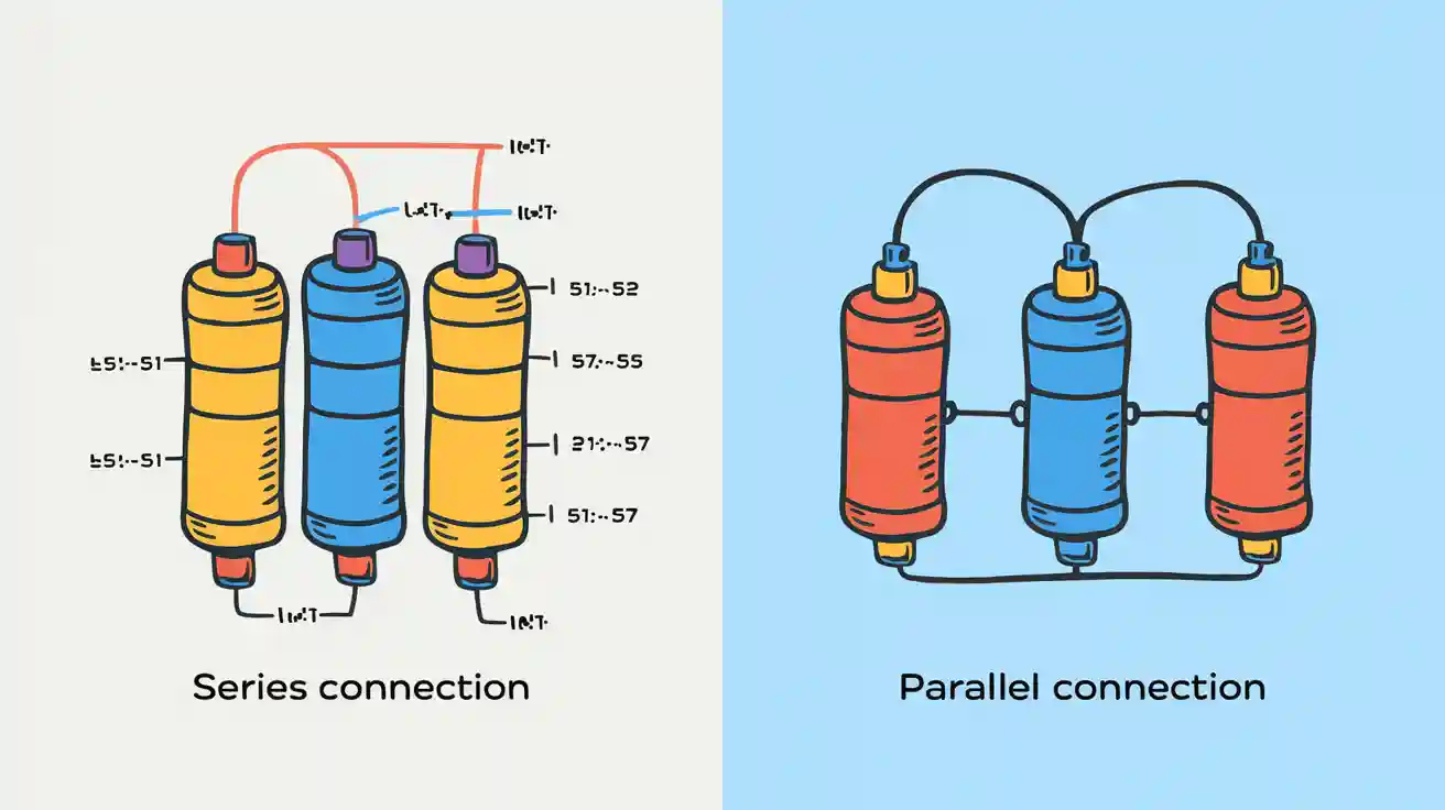
You often face a choice between series connection of capacitors and parallel setups in electronic circuits. In a series connection, voltage splits across each capacitor, while the same charge flows through all. In parallel, voltage stays the same across every capacitor, but each stores different amounts of charge. Understanding these differences helps you balance space, cost, and performance.
Each method offers unique benefits—series setups handle higher voltage, while parallel setups increase total capacitance and energy storage. You will see formulas, examples, and tips for picking the best option.
| Configuration | Voltage Behavior | Current Behavior |
|---|---|---|
| Series | Voltage divides across each capacitor | Same charge passes through all |
| Parallel | Voltage remains the same across capacitors | Different charge based on capacitance |
Key Takeaways
- Series connections split voltage among capacitors, making them ideal for handling higher voltages in circuits.
- Parallel connections keep voltage the same across all capacitors, allowing for increased total capacitance and energy storage.
- In series circuits, if one capacitor fails, the entire circuit stops working. In parallel circuits, other capacitors continue to function, enhancing reliability.
- Use series connections when you need to manage voltage distribution. Choose parallel connections to boost energy storage without changing voltage levels.
Series Connection of Capacitors
What Is a Series Circuit
You can picture a series circuit like a single pipe with several valves in a plumbing system. Water flows through each valve one after another. If you close one valve, water stops everywhere. In a series connection of capacitors, you connect each capacitor end-to-end, so the same current passes through all. The battery acts like a pump, pushing charge through the circuit. Each capacitor acts like a valve that stores charge. All components share the same current, just like water flowing through every valve.
| Series Circuit Concept | Plumbing Analogy |
|---|---|
| Current is the same throughout the circuit | Water flows through a single pipe with several valves |
| If one valve is closed, no water flows | If one component is broken, current stops flowing |
| All components share the same current | All valves allow the same amount of water if open |
Current in Series Circuits
In series circuits, the current stays the same through every capacitor. When you start charging the series connection of capacitors, the current begins strong and then slows down as the capacitors fill up. The current decreases over time because the charge builds up and resists more flow. You see this in the way the water current slows as the pipe fills. The rate of change of charge shows how the current drops until the capacitors reach their maximum charge. Circuit resistors can also affect how quickly the current falls.
Voltage in Series Circuits
The total voltage in a series connection of capacitors splits into individual voltage drops across each capacitor. Kirchhoff's Voltage Law says the total voltage from the battery equals the sum of the voltage drops across all capacitors. Each capacitor gets a share of the potential difference, and the sum of these individual voltage drops always matches the total voltage. The voltage drop across each capacitor depends on its capacitance. You can see how the voltage divides, just like water pressure drops at each valve.
- The total voltage across capacitors in series is the sum of the voltages across each individual capacitor.
- If the total voltage is 5V, then the individual voltage drops will add up to 5V.
| Parameter | Formula |
|---|---|
| Total Capacitance (C_S) | ( \frac{1}{C_{\text{S}}}=\frac{1}{C_{1}}+\frac{1}{C_{2}}+\frac{1}{C_{3}}+\dots ) |
Example Calculation
Suppose you have three capacitors in a series connection of capacitors: 2μF, 4μF, and 6μF. You can find the total capacitance using the formula:
[ \frac{1}{C_{\text{S}}} = \frac{1}{2} + \frac{1}{4} + \frac{1}{6} ]
[ \frac{1}{C_{\text{S}}} = 0.5 + 0.25 + 0.1667 = 0.9167 ]
[ C_{\text{S}} = \frac{1}{0.9167} \approx 1.09,\mu F ]
You see that the total capacitance in series circuits is always less than the smallest capacitor in the series. This is different from equivalent resistance, which adds up in series.
Parallel Connection of Capacitors
What Is a Parallel Circuit
You can imagine a parallel circuit as a set of side-by-side water tanks, each connected to the same water source. In electrical engineering, a parallel connection of capacitors means you connect multiple capacitors across the same two points. Each capacitor works independently, but they all share the same voltage across their terminals. This setup lets you add more storage without changing the voltage in the circuit.
Tip: If you want to increase the total capacitance in your circuit, you should use a parallel connection.
Current in Parallel Circuits
In a parallel circuit, the current splits into different paths. Each capacitor receives its own share of the current based on its size. Larger capacitors take in more current, while smaller ones take in less. You see this in the way water flows into each tank at different rates. The total current in the circuit equals the sum of the currents through each capacitor. This makes parallel circuits useful when you need to store more charge.
| Path | Capacitance | Current Flow |
|---|---|---|
| 1 | Large | More |
| 2 | Small | Less |
Voltage in Parallel Circuits
You notice that the voltage stays the same across every capacitor in a parallel connection. No matter how many capacitors you add, each one gets the full voltage from the power source. This is different from a series circuit, where the voltage divides among the components. You can use this property to make sure all capacitors operate at the same voltage level.
Formulas for Parallel Circuits:
- Total Capacitance:
( C_{\text{P}} = C_1 + C_2 + C_3 + \dots ) - Voltage across each capacitor:
( V_{\text{P}} = V_{\text{source}} ) - Total Current:
( I_{\text{total}} = I_1 + I_2 + I_3 + \dots )
Example Calculation
Suppose you connect three capacitors in parallel: 2μF, 4μF, and 6μF. You add their values together:
[ C_{\text{P}} = 2,\mu F + 4,\mu F + 6,\mu F = 12,\mu F ]
If you apply a voltage of 5V, each capacitor receives 5V. The total current equals the sum of the currents through each capacitor.
Series Circuits vs. Parallel Circuits
Voltage Comparison
You see a big difference in voltage behavior when you compare series and parallel capacitor circuits. In a series circuit, the supply voltage divides among all the capacitors. Each capacitor gets only part of the total voltage. This means the voltage across each one depends on its capacitance. In parallel circuits, every capacitor receives the same supply voltage. No matter how many capacitors you add, each one gets the full voltage from the source.
If you want each capacitor to operate at the same voltage, you should use a parallel connection.
Here is a table that shows how voltage and energy storage work in both types of circuits:
| Configuration | Voltage Behavior | Energy Storage |
|---|---|---|
| Series | Voltage divides among capacitors; same charge | Lower energy storage due to reduced total capacitance |
| Parallel | Voltage is the same across all capacitors; charge varies | Higher energy storage because of increased total capacitance |
Current Comparison
Current and voltage act differently in series and parallel circuits. In a series circuit, the current stays the same through every capacitor. The supply voltage pushes the same charge through each one. If one capacitor fails, the current stops everywhere. In parallel circuits, the total current splits into separate paths. Each capacitor draws its own current based on its capacitance. The total current in the circuit is the sum of the currents through each branch.
- In series circuits, current is constant through all capacitors.
- In parallel circuits, current divides among the branches.
Here is a quick comparison:
| Configuration | Current Behavior | Reliability |
|---|---|---|
| Series | Same current through all capacitors | Failure in one stops the whole circuit |
| Parallel | Current splits among capacitors | Failure in one does not stop the circuit |
Parallel circuits offer better reliability. If one capacitor fails, the others keep working. Series circuits depend on every part, so one failure stops the flow.
Capacitance Comparison
You notice a clear difference in total capacitance between series and parallel circuits. In a series circuit, the total capacitance is always less than the smallest capacitor. This reduces the energy storage. You use the formula:
1/C_total = 1/C1 + 1/C2 + 1/C3 + ...
In parallel circuits, you add up the capacitance values. The total capacitance increases, which lets you store more energy. The formula is simple:
C_total = C1 + C2 + C3 + ...
Here is a table that shows how total resistance and capacitance change in both setups:
| Configuration | Total Capacitance Formula | Effect on Capacitance | Total Resistance Impact |
|---|---|---|---|
| Series | 1/C_total = 1/C1 + 1/C2 + ... | Decreases total capacitance | Increases total resistance |
| Parallel | C_total = C1 + C2 + ... | Increases total capacitance | Decreases total resistance |
You get more energy storage with parallel circuits because the total capacitance is higher. Series circuits limit energy storage since the total capacitance drops.
Quick Reference Table: Series vs. Parallel Capacitor Circuits
| Feature | Series Circuits | Parallel Circuits |
|---|---|---|
| Voltage | Divides among capacitors | Same across all capacitors |
| Current | Same through all capacitors | Splits among branches |
| Total Capacitance | Less than smallest capacitor | Sum of all capacitances |
| Total Resistance | Increases with more components | Decreases with more branches |
| Reliability | Limited by weakest component | Improved by redundancy |
| Energy Storage | Lower due to reduced capacitance | Higher due to increased capacitance |
Tip: When you design circuits, think about how current and voltage will behave. Choose the setup that matches your needs for energy storage, reliability, and supply voltage.
Choosing the Right Connection
When to Use Series Connection
You should use a series connection when you want to increase the total working voltage in your circuit. This setup helps you manage voltage distribution across each capacitor. For example, if you have light bulbs in series, the brightness of light bulbs will change if you add or remove a bulb. The electric current stays the same through each bulb, but the voltage divides among them. This means the brightness of each bulb may not be the same brightness as before. Series connections work well when you need to handle higher voltages, but remember that the total capacitance drops. You may notice a change in brightness if one bulb fails, as the current flow stops everywhere.
- Series connections increase voltage handling.
- Use them when you need to split voltage across components.
- Good for circuits where the same electric current must pass through every part.
When to Use Parallel Connection
Choose a parallel connection if you want to boost total capacitance and store more energy. In this setup, each capacitor gets the same voltage. If you connect light bulbs in parallel, each one shines with the same brightness. The brightness of light bulbs does not change when you add more bulbs, because each gets the full voltage. The current flow splits, so the current through each bulb depends on its own path. Parallel circuits are safer for keeping the same brightness, even if one bulb fails. You also get more electric power and higher energy storage.
- Parallel connections increase total capacitance.
- Use them for circuits that need more energy storage and the same voltage across all parts.
- Ideal for keeping the same brightness in all bulbs.
Application Examples
You see series and parallel connections in many real-world situations. In holiday lights, bulbs in series may dim or all go out if one fails, causing a change in brightness. In home lighting, bulbs wired in parallel keep the same brightness, even if one burns out. This setup ensures the power dissipated from the light bulb stays steady. Engineers often use parallel capacitors in power supplies to store more energy in a small space. Series capacitors help manage high voltage in devices like flash cameras.
Here is a table to help you compare voltage handling, safety, and risks:
| Configuration | Voltage Handling | Safety Margins | Risks |
|---|---|---|---|
| Series | Increased overall working voltage; voltage splits | Need for margin in working voltage | Unequal voltage sharing can cause over-voltage and damage |
| Parallel | All capacitors share the same voltage | Risk if one capacitor fails | High energy storage can cause severe damage if shorted |
Tip: Always balance your choice with space, cost, and performance. Think about how brightness, electric current, and voltage will behave in your circuit.
You now know the key differences between series and parallel capacitor circuits. Check the table below for a quick summary:
| Configuration | Voltage Behavior | Current Behavior | Energy Storage |
|---|---|---|---|
| Series | Voltage divides among capacitors | Same current through all capacitors | Capacitance is less than the smallest capacitor |
| Parallel | Same voltage across all capacitors | Total current is the sum of all currents | Capacitance is the sum of all capacitors |
When you design a circuit, remember these tips:
- Choose the right capacitance for your needs.
- Use capacitors with a voltage rating above your circuit’s voltage.
- Pick low-ESR capacitors to reduce interference.
- Always check polarity before installation.
Try the formulas and examples from this post to build better circuits!
FAQ
What happens if you mix different capacitor values in series?
You get a total capacitance that is less than the smallest capacitor. Each capacitor shares the voltage based on its value. The smallest capacitor gets the highest voltage drop.
Can you increase both voltage and capacitance at the same time?
You cannot increase both at once with only series or parallel connections. Series increases voltage rating, parallel increases capacitance. You can combine both methods for special circuits.
Why do parallel capacitors store more energy?
Parallel capacitors add their values together. You get a higher total capacitance. More capacitance means more energy storage for the same voltage.
Tip: Use parallel connections when you need more energy storage in your circuit.
What is the risk of using series capacitors?
If one capacitor fails, the whole circuit stops working. You must match voltage ratings carefully. Uneven voltage sharing can damage capacitors.
| Risk | Series Connection |
|---|---|
| Circuit stops | Yes |
| Over-voltage | Possible |