Everything You Need to Know About Series and Parallel Resistors
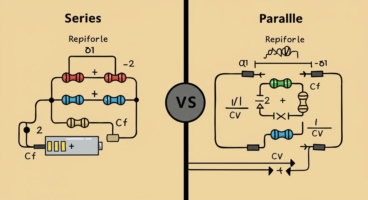
Imagine you are shopping. 🛒 Visiting two shops on one road is like a series connection. Choosing between two separate roads with shops is like a parallel connection.
This article helps you understand the key differences between resistors in parallel vs series. In series circuits, components like resistors form a single path. This setup uses resistors in series. In contrast, parallel circuits create multiple paths for electricity. This arrangement uses resistors in parallel. Grasping the concepts of series and parallel connections is a crucial first step in electronics.
Key Takeaways
- Series circuits have one path for electricity. All components share the same current. If one part breaks, the whole circuit stops.
- Parallel circuits have many paths for electricity. Each part gets the full voltage. If one part breaks, the others still work.
- Adding resistors in a series circuit increases the total resistance. Adding resistors in a parallel circuit decreases the total resistance.
- Home lights use parallel circuits. This lets each light work on its own. If one bulb burns out, the others stay on.
WHAT IS A SERIES CIRCUIT?
A series circuit connects components end-to-end. This creates a single, continuous loop for electricity to flow. Think of it as a one-lane road where all the traffic must follow the same path. If you connect multiple resistors this way, you have created a circuit with resistors in series.
A string of old holiday lights is a great example of a series connection. The electrical current flows through each bulb one after another. If one bulb burns out, it breaks the single path. This interruption stops the flow of current, causing all the lights in the string to go out. This is a key characteristic of a series circuit.
DEFINING A SERIES CONNECTION
You define a series connection by its single path for current. Components like resistors are chained together, one after the other. The end of one resistor connects directly to the beginning of the next. This arrangement is different from a parallel circuit, which provides multiple paths. Understanding this single-path layout is fundamental to working with series circuits.
CURRENT IN A SERIES CIRCUIT
In a series circuit, the current is the same through every component. Since there is only one path, the electricity does not split or change. You can calculate this single current value using Ohm's Law (I = V / Rtotal).
For example, with a 9V source and a total resistance of 18 kΩ, the current is 500 microamps (μA). This exact amount of current flows through all resistors in the series.
To measure this, you can insert an ammeter anywhere in the series loop. You will get the same reading no matter where you place it.
VOLTAGE IN A SERIES CIRCUIT
The total voltage from your power source divides among the resistors in a series circuit. Each resistor creates a "voltage drop." According to Kirchhoff's Voltage Law, the sum of all individual voltage drops must equal the total source voltage. A larger resistor will have a larger voltage drop.
For instance, with a 30V battery and two resistors (4Ω and 6Ω), the total resistance is 10Ω. The current is 3A (30V / 10Ω).
- Voltage drop across the 4Ω resistor:
3A * 4Ω = 12V - Voltage drop across the 6Ω resistor:
3A * 6Ω = 18VThe sum of the drops (12V + 18V) equals the source voltage of 30V.
CALCULATING TOTAL RESISTANCE
Calculating the total resistance for resistors in series is simple. You just add up the values of all the individual resistors. Adding more resistors always increases the total resistance of the circuit. The formula for the equivalent resistance is:
R_equivalent = R1 + R2 + R3 + ...
If you have three resistors with values of 3Ω, 20Ω, and 32Ω connected in series, the equivalent resistance is:
Total Resistance = 3Ω + 20Ω + 32Ω = 55Ω
This final value represents the equivalent resistance for the entire series network.
WHAT IS A PARALLEL CIRCUIT?
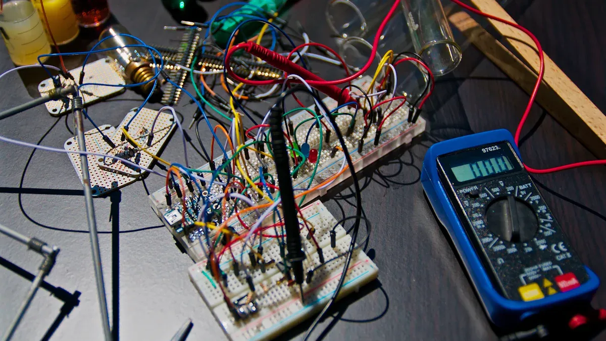
A parallel circuit provides multiple paths for electricity to flow. Unlike a series circuit, components are not connected end-to-end. Instead, they are connected across the same two common points, creating separate branches. You can see a great example of parallel circuits in your home's wiring. This setup ensures that if you turn one light off, the other lights and appliances continue to work because the current still has other paths to follow.
DEFINING A PARALLEL CONNECTION
You define a parallel connection by its multiple branches for current. Imagine a river splitting into several smaller streams that later rejoin. In electronics, you connect the leads of all your components (like resistors) to the same two points in the circuit. This arrangement is the core of how parallel circuits function, offering a distinct alternative to a single-path series connection.
VOLTAGE IN A PARALLEL CIRCUIT
For example, if you connect three different resistors to a 9V battery in parallel, each one of those resistors will have exactly 9V across it. This rule is fundamental to understanding parallel circuits.
CURRENT IN A PARALLEL CIRCUIT
The total current from the power source splits among the different branches in a parallel circuit. This follows a rule called Kirchhoff's Current Law, which states that the total current entering a junction must equal the total current leaving it. The current does not split evenly; more current will flow through the path of least resistance. A branch with a smaller resistor will get a larger share of the current, while a branch with a larger resistor will get less.
CALCULATING TOTAL RESISTANCE
Calculating the total resistance for resistors in parallel is more complex than for a series circuit. The total resistance, also called the equivalent resistance, is always less than the value of the smallest individual resistor. Adding more resistors in parallel actually decreases the total resistance because you are adding more paths for the current to flow.
You calculate the equivalent resistance using the reciprocal formula:
1/R_equivalent = 1/R1 + 1/R2 + 1/R3 + ...
For example, if you have two 10Ω resistors in parallel, the equivalent resistance is 5Ω. This lower total resistance allows more total current to flow from the source.
RESISTORS IN PARALLEL VS SERIES: KEY DIFFERENCES
Understanding the core distinctions between resistors in parallel vs series helps you predict how a circuit will behave. The way you connect your resistors fundamentally changes the circuit's properties, from current flow to total resistance. Let's break down these key differences.
PATHS FOR CURRENT
The most important difference is the number of paths available for the current.
- A series circuit provides only one path. The electricity must flow through every component, one after the other, like cars on a single-lane road.
- A parallel circuit offers multiple paths. Each electrical device sits in its own branch. When the current reaches a junction, it splits and travels through the different branches before rejoining later.
Think of it this way: In a series circuit, you have to visit every shop on a single street. In a parallel circuit, you can choose which of the several available streets you want to go down.
TOTAL RESISTANCE BEHAVIOR
How you arrange resistors directly impacts the circuit's total resistance.
In a series circuit, the total resistance is the simple sum of all individual resistors. Adding more resistors in series always increases the total resistance because you are making the single path longer and more difficult for the current to travel.
- Formula:
R_total = R1 + R2 + R3 + ... - Example: If you connect a 4Ω resistor and a 6Ω resistor in series, your total resistance becomes
4Ω + 6Ω = 10Ω.
In a parallel circuit, the opposite happens. Adding more resistors in parallel decreases the total resistance. You are creating more pathways for the current, making it easier for electricity to flow. The total resistance will always be less than the smallest individual resistor in the circuit.
VOLTAGE DISTRIBUTION
Voltage behaves very differently depending on the circuit type. In a series circuit, the source voltage is divided among the components. In a parallel circuit, every component gets the full source voltage.
You can see a quick summary in this table:
| Feature | Series Circuit | Parallel Circuit |
|---|---|---|
| Voltage | Divided across components | Same across all components |
This property makes resistors in series useful as voltage dividers. You can use them to supply a specific, lower voltage to a part of a circuit. Practical applications include:
- Sensor Interfacing: Using sensors for light or temperature to produce a specific voltage output.
- Potentiometers: These act as adjustable voltage dividers, like the volume knob on a stereo.
- Biasing Circuits: Setting the correct operating voltage for components like transistors.
CURRENT DISTRIBUTION
Just as voltage splits in a series circuit, current splits in a parallel circuit.
- Series: The current is the same through every single component. Since there is only one path, the flow of electricity is constant everywhere in the loop.
- Parallel: The total current from the source divides among the branches. More current will flow through branches with lower resistance.
This current-sharing ability is a key feature of parallel circuits. Designers use this principle in high-power applications where a single component cannot handle the required current.
- Solar Fields: Solar panels are connected in parallel to increase the total current output.
- Power Electronics: Multiple components like MOSFETs are placed in parallel to share a large current load, ensuring the system operates reliably.
CIRCUIT BEHAVIOR IF A RESISTOR FAILS
The final key difference in resistors in parallel vs series is reliability. What happens if one of the resistors breaks and creates an open circuit?
In a series circuit, a single failure is catastrophic. An open resistor breaks the only path for current. As a result, the entire circuit stops working. No current can flow, and all components shut down. The full voltage of the power source will appear across the broken component.
In a parallel circuit, the system is more resilient. If a resistor in one branch fails, it only interrupts the current flow in that specific branch. The other branches remain unaffected and continue to operate because their paths to the power source are still complete. This is why the lights in your house don't all go out when one bulb burns out.
The key difference in resistors in parallel vs series is the number of paths available for current. A series circuit provides only one path, making the current the same through all resistors. A parallel circuit offers multiple paths, which keeps the voltage the same across each branch. This multi-path design also makes parallel circuits more reliable. If one path fails, the others continue to work.
You now understand the foundational building blocks of most electronic circuits. Great job! 💡
FAQ
### Why does adding resistors in parallel decrease resistance?
Adding resistors in parallel creates more paths for the current to flow. Think of it like opening more checkout lanes at a store. 🛒 More lanes allow more people to check out at once. This makes the overall flow easier, which means the total resistance is lower.
### Which circuit is used for lights in a house?
Your home uses parallel circuits for its wiring and outlets. This design is very practical. It allows you to turn on one light or appliance without affecting any others. If one bulb burns out, the rest of your lights will stay on.
### Can you mix series and parallel connections?
Yes, you absolutely can! Circuits that combine both series and parallel parts are called "combination circuits" or "series-parallel circuits." Most electronic devices, from your phone to your TV, use these more complex combination circuits to function correctly.
### Are light bulbs brighter in a series or parallel circuit?
Light bulbs are much brighter in a parallel circuit.
In a parallel circuit, each bulb gets the full voltage from the power source. In a series circuit, the bulbs must share the voltage, so each one gets less power and shines more dimly. 💡