Why Pull-up and Pull-down Resistors Matter in Reliable Digital Systems
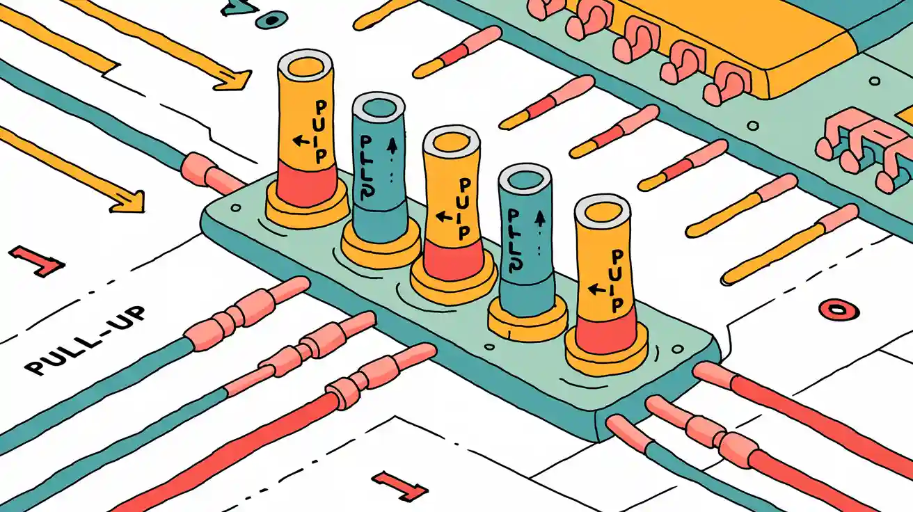
Reliable digital circuit design depends on keeping logic signals stable. Pull up and pull down resistors play a key role in preventing floating inputs and undefined logic states. These resistors connect uncertain signals to either ground or supply voltage, securing a predictable logic level.
- Pull-up resistors maintain a high input state, blocking low-level interference.
- Pull-down resistors keep signals low, stopping noise and erratic switching.
- Both types help eliminate unpredictable behavior and reduce switching time lag.
Engineers use pull up and pull down resistors to boost noise immunity and ensure consistent operation in every digital circuit.
Key Takeaways
- Pull-up and pull-down resistors keep digital inputs stable by connecting them to a known voltage level, preventing unpredictable circuit behavior.
- Pull-up resistors set inputs to a high state, while pull-down resistors set inputs to a low state, ensuring clear and reliable logic signals.
- These resistors protect circuits from noise and errors by blocking unwanted signals and reducing power consumption.
- Choosing the right resistor value balances power use and signal speed, improving circuit performance and reliability.
- Including pull-up or pull-down resistors in designs helps avoid floating inputs, making digital systems safer and more robust.
Importance of Pull Up and Pull Down Resistors
Preventing Floating Inputs
Digital circuits rely on clear signals to work correctly. Pull-up and pull-down resistors help keep each input pin at a defined logic level. When an input pin is left unconnected, it can float between high and low voltage. This floating state causes unpredictable behavior in the circuit. Pull-up resistors connect the input pin to the positive supply voltage through a resistor. This setup ensures the input pin reads as a logic HIGH when no other connection is present. Pull-down resistors connect the input pin to ground, making sure it reads as a logic LOW when not driven by another source.
Without pull-up or pull-down resistors, floating inputs can cause several problems:
- The input pin may randomly switch between high and low, leading to erratic circuit operation.
- Undefined logic levels can increase power consumption and drain batteries faster.
- Floating inputs may pick up signals from nearby pins, causing false triggers or resets.
- The circuit may become more sensitive to static electricity, which can damage components.
Pull up and pull down resistors prevent these issues by always providing a path to a known logic level. This action keeps the circuit stable and reliable.
Ensuring Stable Logic Levels
Stable logic levels are essential for digital systems. Pull-up resistors guarantee that an input pin defaults to a logic HIGH when not connected to another signal. Pull-down resistors ensure the input pin defaults to a logic LOW. This design prevents the input pin from floating and keeps the logic level clear.
A pull-up resistor limits the current when the input pin switches from HIGH to LOW. This protection stops damage to the circuit. Pull-down resistors work in a similar way, keeping the input pin at a safe logic level. Engineers use pull up and pull down resistors to make sure every input pin has a defined logic level at all times.
| Resistor Type | Connects Input Pin To | Default Logic Level |
|---|---|---|
| Pull-up | Positive Voltage | HIGH |
| Pull-down | Ground | LOW |
Pull-up and pull-down resistors form the backbone of reliable digital circuits. They keep logic levels steady and prevent errors caused by floating inputs.
Pull-up and Pull-down Resistor Basics
What Is a Pull-up Resistor
A pull-up resistor is a standard resistor that connects an input pin to the positive supply voltage, such as 5V or 3.3V. This resistor ensures the input pin stays at a high logic level when no other device drives the line. Pull-up resistors prevent floating inputs by providing a clear path to the supply voltage. When the input pin is not connected to anything else, the pull-up resistor keeps the voltage steady and avoids undefined logic states. Engineers use pull-up resistors in digital circuits to stabilize the input pin and limit current flow, which helps protect the circuit from damage. Pull-up resistors are not special types of resistors; they perform a specific job by pulling the voltage up to a high level.
Tip: Pull-up resistors are common in microcontroller input pins, open-collector outputs, and switch circuits. They help avoid unpredictable behavior caused by floating signals.
What Is a Pull-down Resistor
A pull-down resistor connects an input pin to ground. This resistor keeps the input pin at a low logic level when no other signal is present. Pull-down resistors absorb current from the device and prevent the input pin from floating. When a circuit needs a default low state, engineers use a pull-down resistor to make sure the input pin reads as logic LOW. Pull-down resistors are often used on transistor bases and in digital circuits where a low default state is needed. They help discharge any leftover charge and set a clear bias voltage.
Differences and Applications
Pull-up and pull-down resistors both keep input pins at known logic levels, but they work in opposite ways. Pull-up resistors connect the input pin to the power supply, setting a default high state. Pull-down resistors connect the input pin to ground, setting a default low state.
- Pull-up resistors supply current to the input pin and ensure a high logic level.
- Pull-down resistors absorb current and ensure a low logic level.
- Pull-up resistors are widely used in open-collector or open-drain outputs, microcontroller input pins, and logic gate circuits.
- Pull-down resistors are used to prevent noise, avoid time lag, and set bias voltages in digital circuits.
| Feature | Pull-up Resistor | Pull-down Resistor |
|---|---|---|
| Connects to | Positive voltage (Vcc) | Ground |
| Default logic level | High | Low |
| Common applications | Microcontroller inputs, open-collector outputs, logic gates | Transistor bases, biasing, noise prevention |
Pull up and pull down resistors play a vital role in digital systems. They keep input pins stable, prevent errors, and ensure reliable operation in many types of circuits.
Operation in Digital Circuits
Setting Default Logic States
Engineers design digital circuits to operate with predictable logic levels. Pull-up resistors connect input pins to a positive voltage, such as 5V, through a resistor. This connection keeps the input pin at a logic HIGH when no other signal is present. Pull-down resistors link the input pin to ground, setting the default logic level to LOW. These resistors prevent input pins from floating, which can cause unpredictable circuit performance.
Microcontroller and digital gate circuits often use pull-up resistors to maintain a stable logic HIGH state. When a switch is open, the pull-up resistor ensures the input remains HIGH. Pressing the switch connects the pin to ground, changing the logic level to LOW. Pull-down resistors work in the opposite way. They keep the input at logic LOW until an external signal pulls it HIGH. This method provides reliable signal conditioning and avoids floating inputs.
The use of pull-up resistors limits current flow, protecting the circuit from damage. If an input pin connects directly to voltage or ground, excessive current can flow, risking component failure. Pull-down resistors also help by controlling the current and maintaining a safe logic level. Many microcontrollers include internal pull-up resistors to simplify design and improve circuit performance.
The consequences of not setting default logic states with pull-up or pull-down resistors can be severe. The table below shows common issues and their impact on circuit performance:
| Consequence/Issue | Explanation | Impact |
|---|---|---|
| Undefined/Floating Inputs | Inputs left unconnected can float to any voltage, causing unpredictable logic levels and susceptibility to electrical noise. | Leads to unreliable circuit performance and potential logic errors. |
| CMOS Inputs in Linear Region | Floating inputs near mid-level voltage cause CMOS transistors to operate in linear region, drawing excessive current. | Increases power consumption beyond design budget, potentially damaging battery life in portable devices. |
| Increased Power Consumption | Example from quartz watch design: floating input increased current from 1.5µA to 5µA, reducing battery life from 1.5 years to less than 0.5 years. | Financial loss and product delivery delays due to reduced device reliability. |
| Software-Enabled Internal Pull-ups Insufficient at Power-up | Internal pull-ups activated by software may not be enabled immediately during power-up or reset, leaving inputs floating temporarily. | Risk of undefined states and increased current draw during critical startup phases. |
| Noise Susceptibility | Floating inputs can pick up static charge or electromagnetic interference, causing erratic input readings. | Erroneous logic states and unstable system operation. |
| Design Best Practice | Always define input states with pull-up or pull-down resistors, either external or internal, to ensure stable logic levels. | Prevents unpredictable behavior and ensures reliable system function. |
Pull-up resistors and pull-down resistors set clear default logic levels. They ensure digital circuits operate reliably and maintain consistent circuit performance.
Protecting Against Noise and Errors
Digital systems face many sources of electrical noise. Pull-up resistors and pull-down resistors play a vital role in protecting circuits from these disturbances. Pull-up resistors connect digital inputs to a high voltage level. This connection keeps the input stable at a logic HIGH and blocks low-level noise that could cause malfunctions. Pull-down resistors connect inputs to ground, stabilizing the input at a logic LOW and preventing high-level noise interference.
Without pull-up or pull-down resistors, input terminals can float. Floating inputs are vulnerable to external electrical noise, which can induce unwanted voltage changes and signal errors. Pull-down resistors on transistor bases prevent noise-induced malfunctions by reliably cutting off the transistor when no input signal is present. They also help discharge residual charges, avoiding signal distortion.
Pull-up resistors improve noise tolerance and reduce electromagnetic interference. They protect against static electricity damage and suppress reflected wave interference in long-line transmissions. Both pull-up and pull-down resistors enhance signal integrity and reduce error rates by preventing undefined or floating input states.
- Pull-down resistors prevent noise interference by fixing uncertain signals to a defined low level. This action ensures reliable transistor cut-off and avoids malfunctions caused by noise, especially during unstable states like power-on initialization of GPIOs.
- They help discharge residual charges in MOS transistor gates, preventing logic errors caused by capacitance effects.
- Pull-up resistors increase output high levels and supply current when bus drive capability is insufficient. This improvement stabilizes signal levels and prevents floating inputs.
- Pull-up resistors also protect against static electricity damage and suppress reflected wave interference in long-line transmissions by matching resistance.
- Both types of resistors improve signal integrity and reduce error rates by enhancing electromagnetic interference resistance.
Engineers rely on pull-up resistors and pull-down resistors to maintain stable logic levels, improve circuit performance, and ensure reliable operation in every digital circuit. These components form the foundation of effective signal conditioning and robust digital design.
Value Selection for Pull-up and Pull-down Resistors
Choosing the Right Value
Selecting the correct value for a pull-up or pull-down resistor is important for reliable digital systems. Engineers consider several factors when making this choice. The resistor value affects how much current flows through the circuit. A lower resistance allows more current, which can increase power consumption. A higher resistance saves power but may not keep the input pin at a strong logic level. The right balance helps maintain signal integrity and good circuit performance.
Factors to consider include:
- Power dissipation: Lower resistance increases current and power loss.
- Signal integrity: The resistor must be strong enough to hold the input at a valid logic level, even with leakage currents.
- Input pin impedance: The resistor should be at least ten times smaller than the pin’s impedance.
- Switching speed: The resistor and input capacitance form an RC time constant. A large resistor slows down signal transitions, which can affect high-speed circuits.
- Application type: For 5-V bipolar logic, values between 1 kΩ and 5 kΩ are common. For CMOS circuits, values from 10 kΩ to 1 MΩ work well.
Simple calculations help engineers choose the right resistor value. For a pull-up resistor, use the formula:
R_pull-up = (V_supply - V_H(min)) / I_sink
For a pull-down resistor, use:
R_pull-down = V_L(max) / I_source
These formulas use values from datasheets to ensure the resistor keeps the input at a defined logic level. Proper selection improves signal integrity and circuit performance.
Tip: Always check the datasheet for recommended resistor values for each pin. This step helps avoid logic errors and ensures stable operation.
Common Mistakes
Engineers sometimes make mistakes when choosing pull-up and pull-down resistor values. These errors can harm signal integrity and circuit performance.
Common mistakes include:
- Using a resistor that is too small. This choice causes excessive current and power loss.
- Selecting a resistor that is too large. The input pin may not reach a valid logic level, leading to unreliable signals.
- Ignoring the RC time constant. Large resistors with capacitive loads slow down signal transitions.
- Not checking the load impedance. The resistor must be much smaller than the load impedance to maintain proper voltage levels.
- Overlooking datasheet recommendations. Each pin may have a maximum resistor value for correct operation.
| Mistake | How to Avoid |
|---|---|
| Resistor too large | Choose a value that provides enough drive current for fast signals |
| Resistor too small | Calculate minimum value to prevent excessive current |
| Ignoring load impedance | Match resistor to load for valid voltage levels |
| Not considering frequency | Account for capacitance and switching speed |
| Skipping datasheet check | Always refer to datasheet for pin limits |
Engineers improve signal integrity and circuit performance by avoiding these mistakes. Careful selection of pull-up and pull-down resistors keeps digital systems reliable.
Real-world Use Cases

Microcontroller Inputs
Microcontrollers rely on pull-up and pull-down resistors to keep each input pin at a defined logic level. When a microcontroller starts, its input pins often act as high-impedance inputs. If an input pin floats, the microcontroller may read unpredictable values. Engineers use pull-up resistors to connect the input pin to the supply voltage, setting a default high state. Pull-down resistors connect the input pin to ground, ensuring a low state when no input signal is present.
Typical resistor values for these applications range from 1kΩ to 100kΩ. Many designs use 10kΩ or 5kΩ resistors. The choice depends on current requirements, voltage ratings, and the type of resistor. Carbon film resistors work well for general use, while metal film resistors offer better noise performance in sensitive circuits. Surface mount resistors help save space on compact boards.
Pull-up and pull-down resistors prevent floating inputs, which can cause false triggers or erratic behavior. They also protect the microcontroller during startup, when input pins may not have a defined state. In open-drain configurations, pull-up resistors ensure the line reaches a proper high level when not driven low. These resistors do not interfere with normal operation because they use high resistance values.
Tip: Always select a resistor with a power rating at least twice the calculated dissipation. This practice improves reliability and prevents overheating.
Digital Gate Applications
Digital logic gates need stable input pin voltages to function correctly. Pull-up resistors connect the input pin to a positive rail, setting a default high logic level. Pull-down resistors connect the input pin to ground, setting a default low logic level. Switch inputs often use pull-up resistors so the input pin reads high until the switch grounds the pin, causing it to read low.
Digital logic gates also use pull-up resistors for bidirectional communication lines, such as I2C buses. These resistors keep the line high when no device pulls it low. Sensors and switches use pull-down resistors to provide stable voltage levels for analog-to-digital conversion and digital input reading.
Common errors in digital logic gates include leaving input pins floating, using incorrect resistor values, and neglecting power consumption. The table below lists frequent mistakes and their consequences:
| Frequent Error | Description | Consequence |
|---|---|---|
| Using incorrect resistor values | Non-standard values increase cost and risk poor quality | Circuit failure, higher cost |
| Leaving input pins floating | Unconnected pins pick up interference | Oscillating states, instability |
| Improper value selection | Too large or small causes power loss or signal delay | Increased power, slow signals |
| Ignoring power on buses | Not considering total power draw | Reduced device lifetime |
| Misunderstanding signal integrity | Poor balance of size and efficiency | Noise, instability, damage |
Digital logic gates and microcontrollers both depend on pull-up and pull-down resistors to prevent floating input pins and maintain reliable operation. These resistors ensure each digital logic device receives stable signals, avoiding unpredictable behavior.
Pull-up and pull-down resistors keep digital circuits stable and reliable.
- Pull-up resistors connect inputs to a high voltage, preventing floating signals and reducing noise.
- Pull-down resistors hold inputs low, stopping erratic switching and unwanted activation.
- Proper resistor values balance power use and signal speed.
- Typical values range from 1kΩ to 100kΩ, with 10kΩ common for buttons and I2C lines.
Engineers should always include these resistors in their designs to avoid unpredictable behavior and ensure safe, robust digital systems.
FAQ
What happens if a digital input pin floats?
A floating input pin can pick up noise. The pin may switch between high and low states. This behavior can cause the circuit to act unpredictably.
How does someone choose between a pull-up and a pull-down resistor?
Engineers select a pull-up resistor to set a default high state. They use a pull-down resistor for a default low state. The choice depends on the logic needed for the circuit.
Can a microcontroller use internal pull-up resistors?
Many microcontrollers have built-in pull-up resistors. Engineers can enable these through software settings. Internal pull-ups save space and parts on the circuit board.
What resistor value works best for most digital inputs?
| Application | Typical Value |
|---|---|
| Switch/Button Input | 10kΩ |
| I2C Bus | 4.7kΩ |
| General Logic Pin | 10kΩ |
Engineers often use 10kΩ for general inputs. The best value depends on the circuit.