Pin Assignment for RJ45 Ethernet Cables Explained
You rely on the correct pin assignment rj45 when building or repairing any network cable. Consistent rj45 pinout and color codes play a crucial role in maintaining stable network connections. Using a standard pinout reduces wiring errors and keeps your rj45 connections reliable.
- Enterprises that use color-coded rj45 cabling report faster troubleshooting and fewer outages.
- Standardized pin assignment rj45 ensures you avoid crossed wires and signal loss.
- Color codes make tracing and expanding your network cable setup easier.
You can master rj45 pinout quickly. With the right guide, you will see that setting up a network cable becomes a straightforward task.
Key Takeaways
- Use the correct RJ45 pin assignment and color codes to build reliable network cables and avoid connection problems.
- Follow either the T568A or T568B wiring standard consistently on both ends of your cable to ensure proper communication.
- Choose straight-through cables for connecting different devices and crossover cables for connecting similar devices directly.
- Always double-check wire order before crimping and use cable testers to find and fix wiring mistakes early.
- Select the right RJ45 connector type for your cable and handle cables carefully to prevent damage and signal loss.
Pin Assignment RJ45
RJ45 Pinout Table
You need to understand the official standards before you start wiring any network cable. The T568A and T568B wiring schemes set the rules for pin assignment rj45. These standards come from ANSI, TIA, and EIA. Most people use T568B as the default, but T568A is also common, especially in government projects. Both standards use eight wires inside the cable and connect them to an 8P8C modular plug, which most people call an rj45 connector.
Here is a pinout table that shows the color and function for each pin in both T568A and T568B. This pin diagram helps you see the difference between the two standards:
| Pin Number | T568A Color | T568A Function | T568B Color | T568B Function |
|---|---|---|---|---|
| 1 | Green White | +BI_DA | Orange White | +BI_DA |
| 2 | Green | -BI_DA | Orange | -BI_DA |
| 3 | Orange White | +BI_DB | Green White | +BI_DB |
| 4 | Blue | +BI_DC | Blue | +BI_DC |
| 5 | Blue White | -BI_DC | Blue White | -BI_DC |
| 6 | Orange | -BI_DB | Green | -BI_DB |
| 7 | Brown White | +BI_DD | Brown White | +BI_DD |
| 8 | Brown | -BI_DD | Brown | -BI_DD |
You can use this pinout as a quick reference when you wire rj45 connectors. The pin assignment rj45 must match on both ends of a straight-through cable to keep your network stable.
Color Codes
Color codes make it much easier to wire a network cable without mistakes. Each wire inside the cable has a color that matches a specific pin on the rj45 connector. You follow these color codes to make sure each wire goes to the right spot. This keeps your rj45 pinout correct and your network working well.
- Color codes match the T568A or T568B standards, showing you the exact order for each wire.
- You use the colors as a visual guide to line up the wires with the right pins on the rj45 connector.
- Following the color codes helps you avoid wiring errors and keeps your pinout consistent.
- Color coding also helps you keep wire pairs together, which is important for network performance.
- When you stick to the color codes, you prevent network failures caused by miswiring.
Tip: Always double-check the color order before you crimp the rj45 connectors. This simple step can save you hours of troubleshooting later.
Pin Functions
Each pin on the rj45 connector has a special job in the network. The pin assignment rj45 makes sure that data travels the right way between devices. If you mix up the pins, your network cable will not work right. You might see slow speeds, dropped connections, or no connection at all.
Here is a table that shows what each pin does in a typical rj45 pinout (using T568B as an example):
| Pin Number | Assigned Function | Description | Typical Wire Color (T568B) |
|---|---|---|---|
| 1 | Transmit Data + (TX+_D1) | Sends positive transmit signal | White with orange stripe |
| 2 | Transmit Data - (TX-_D1) | Sends negative transmit signal | Solid orange |
| 3 | Receive Data + (RX+_D2) | Receives positive data signal | White with green stripe |
| 4 | Bi-directional + (BI+_D3) | Used for bi-directional signals | Solid blue |
| 5 | Bi-directional - (BI-_D3) | Used for bi-directional signals | White with blue stripe |
| 6 | Receive Data - (RX-_D2) | Receives negative data signal | Solid green |
| 7 | Bi-directional + (BI+_D4) | Used for bi-directional signals | White with brown stripe |
| 8 | Bi-directional - (BI-_D4) | Used for bi-directional signals | Solid brown |
You see that some pins send data, some receive data, and others handle signals in both directions. This setup supports fast data transfer and features like Power over Ethernet (PoE). If you do not follow the correct pinout, your rj45 connectors will not work as expected.
Incorrect pin assignment rj45 can cause many problems:
- Devices may not communicate, like a language barrier.
- You may get slow speeds, high latency, or no connection.
- Poor terminations can cause signal interference and crosstalk.
- Your network cable may need to be re-crimped or tested to fix these issues.
You can avoid these problems by learning the pin diagram and following the right pinout every time you make a network cable. This knowledge keeps your rj45 connector reliable and your network strong.
T568A vs T568B

Wiring Differences
When you compare t568a vs t568b, you see that both follow the same rj45 wiring standards. The main difference comes from how you arrange the colored wire pairs inside the rj45 connector. T568A and T568B both use eight wires, but they swap the green and orange pairs on pins 1, 2, 3, and 6. The blue and brown pairs stay in the same place for both standards.
Here is a table to help you see the difference:
| Pin | T568A | T568B |
|---|---|---|
| 1 | white/green | white/orange |
| 2 | green | orange |
| 3 | white/orange | white/green |
| 4 | blue | blue |
| 5 | white/blue | white/blue |
| 6 | orange | green |
| 7 | white/brown | white/brown |
| 8 | brown | brown |
You must use the same wiring scheme on both ends of your rj45 cable. If you mix T568A and T568B, your network connection will not work. Both standards give you the same performance, so you do not need to worry about speed or reliability when choosing one over the other.
Tip: Always double-check your wire order before crimping the rj45 connector. This step helps you avoid common wiring mistakes.
When to Use Each
You might wonder when to use T568A or T568B for your rj45 cables. T568A is often the best choice for home networks. It works well with older devices, such as fax machines and some wireless phone base stations. Many standards recommend T568A for residential use because it keeps your network compatible with legacy equipment.
T568B is very popular in offices and commercial buildings. Many installers choose T568B because it matches older AT&T color codes and is easy to remember. You see T568B used for patch panels, wall jacks, and most business network setups. Both t568a vs t568b work for straight-through Ethernet cables, so you can use either as long as you stay consistent.
- Use T568A for:
- Home networks
- Older devices that need backward compatibility
- Use T568B for:
- Office and commercial networks
- Projects where T568B is already in use
No matter which standard you pick, always use the same one on both ends of your rj45 cable. This habit keeps your network stable and helps you follow the best rj45 wiring standards.
RJ45 Connector Types
8P8C Modular Plug
You will find that the 8P8C modular plug is the most common type used for Ethernet cables. The term "8P8C" stands for "eight positions, eight contacts." This means the rj45 connector has eight slots for wires and eight metal contacts to connect those wires. You can use this plug to connect four twisted wire pairs, which is perfect for modern networking.
Here are some important features of the 8P8C modular plug:
- The rj45 connector includes a small plastic tab. This tab locks the plug into place and ensures you insert it in the correct direction.
- The metal contacts sit inside plastic channels. These contacts touch the wires and create a secure connection.
- You do not need to solder anything. The rj45 connector supports solderless assembly, so you can make cables quickly with simple tools.
- Many rj45 connectors have shielding to protect against electromagnetic interference (EMI) and radio frequency interference (RFI).
- Some rj45 connectors include extra features like connection status lights or integrated magnetics for better protection.
Tip: The gold plating on the contact area helps the rj45 connector last through hundreds of uses without losing connection quality.
The design also supports both solid and stranded copper wires. Strain relief features hold the cable jacket tightly, so the wires do not move or break after you crimp the rj45 connector.
Physical Layout
The physical layout of the rj45 connector helps you line up each wire with the correct pin. You will see eight pins inside the connector, each matching a specific color in the T568A or T568B standard. The plastic tab on the rj45 connector makes sure you cannot insert it the wrong way. This design keeps your network safe from wiring mistakes.
You may notice that rj45 connectors come in different styles for different cable types. For example:
- Cat5 rj45 connectors have straight holes for the wires.
- Cat6 rj45 connectors often use a staggered pin layout to fit thicker wires.
- Shielded rj45 connectors have a metal cover to block EMI. You should use these with shielded Ethernet cables.
- Pass-through rj45 connectors let the wires go all the way through the plug, making it easier to check the order before crimping.
- Some rj45 connectors use a two-piece design with a load bar to help align the wires.
You should always check that the rj45 connector matches your cable’s size and type. The right fit improves connection stability and network performance.
Note: The rj45 connector’s design, including the tab and pin layout, ensures each wire lines up with the correct pin. This setup supports fast, accurate data transmission and helps prevent errors.
Ethernet Cable Pinout
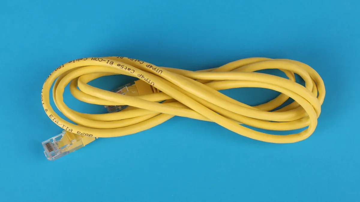
When you build a network cable, you need to follow the correct ethernet cable pinout. This ensures your devices talk to each other without problems. The pinout tells you how to arrange the wires inside the rj45 connector. You will use either a straight-through or a crossover cable, depending on your network setup.
Straight-Through Cable
A straight-through cable is the most common type of network cable. You use it to connect different types of devices, such as a computer to a switch or a router to a modem. Both ends of the cable use the same rj45 pinout, usually T568B.
How to make a straight-through cable:
- Gather your materials: network cable (CAT5, CAT5e, or CAT6), two rj45 connectors, and a crimping tool.
- Strip about 1.5 cm of the outer jacket from both ends of the cable.
- Untwist the wire pairs and arrange them in the correct order for your chosen pinout (T568A or T568B).
- Trim the wires so they are even.
- Insert the wires into the rj45 connector, making sure each wire reaches the end.
- Crimp the connector with the tool.
- Repeat for the other end, using the same pinout.
- Test the cable to check for proper connections.
Tip: Always double-check the wire order before crimping. A small mistake can cause network issues.
Matching the pinout on both ends keeps your network stable. If you mix up the order, your ethernet pinout signal will not work as expected.
Crossover Cable
A crossover cable lets you connect two devices of the same type, like two computers or two switches, without extra equipment. This cable swaps the transmit and receive wires, so the devices can talk directly.
How to make a crossover cable:
- Gather your materials: network cable, two rj45 connectors, and a crimping tool.
- Strip the outer insulation from both ends.
- On one end, arrange the wires in the T568A order. On the other end, use the T568B order.
- Align and trim the wires so they are even.
- Insert the wires into the rj45 connectors and crimp them.
- Test the cable to make sure it works.
| Cable Type | Typical Use Cases |
|---|---|
| Straight-Through | Connecting devices of different types (computer to switch, switch to router, router to modem) |
| Crossover | Connecting devices of the same type directly (two computers, two switches, two routers) |
Some modern devices use Auto-MDIX, which can detect and adjust for cable type. Older devices still need the correct cable for the network to work.
Note: Using the right ethernet cable pinout for your rj45 connectors prevents signal loss and keeps your network cable reliable.
Testing and Troubleshooting
Testing Tools
You can test your rj45 connector and network cable with special tools designed for this job. A cable tester like the Noyafa NF-8601S helps you check the pinout and find wiring problems quickly. This device shows you if your rj45 connector has any faults, such as open circuits, shorts, or crossed wires. You connect one end of the cable to the main unit and the other to the remote. The tester then displays results on a screen, making it easy to see if your pinout matches the standard.
Other professional tools also help you find problems in your rj45 connector:
- Fluke Networks Pro3000™ Tone Generator sends a signal through the cable so you can trace it.
- TS100-PRO-BT-TDR Cable Fault Finder locates open or short circuits and measures cable length.
- Wiremap testers use LEDs to show if your rj45 connector is wired correctly.
- Network cable testers display real-time results and work with CAT5, CAT5e, and CAT6 cables.
Tip: Always test your rj45 connector with a known good cable first. This step checks if your tester works before you test new cables.
Common Issues
You may run into common problems when making or using an rj45 connector. Mixing T568A and T568B standards on each end of the cable can cause the network to fail. Poor crimps lead to loose connections. If you untwist the wire pairs too much, your network cable becomes more likely to pick up interference. Skipping cable testing means you might miss miswires or open circuits. Exceeding 100 meters in cable length can cause signal loss. Tight bends or lack of strain relief can damage the rj45 connector.
If you have trouble with your network, follow these steps:
- Use a cable tester to check the rj45 connector and pinout.
- If a pin fails, re-crimp both ends with new connectors.
- Replace the network cable if problems continue.
- Make sure all devices and cables are plugged in and powered on.
- Double-check that you use the same pinout on both ends.
Note: Pins 1, 2, 3, and 6 are vital for most Ethernet speeds. Always follow the correct pinout to keep your network strong.
You can build a strong network by following the correct rj45 pinout and wiring standards. Proper pin assignment keeps transmit and receive pins in line, which helps your network run smoothly. Always double-check your work and use cable testers to catch mistakes early.
For long-term success, remember these best practices:
- Label and document cables.
- Avoid sharp bends and overcrowding.
- Test cables before and after installation.
- Plan for future needs and keep your setup organized.
FAQ
What happens if you mix T568A and T568B on one cable?
You will create a crossover cable. This cable only works for connecting similar devices, like two computers. If you want a standard network connection, use the same wiring standard on both ends.
Can you use a straight-through cable for all network connections?
You can use a straight-through cable for most connections, such as connecting a computer to a switch or router. Some older devices need a crossover cable, but most modern equipment supports Auto-MDIX and works with straight-through cables.
How do you identify pin 1 on an RJ45 connector?
Hold the RJ45 connector with the clip facing down and the contacts facing you. Pin 1 is the leftmost pin. Always start wiring from this side to keep the color order correct.
Do you need special tools to make Ethernet cables?
Yes, you need a cable stripper, a crimping tool, and a cable tester. These tools help you strip the cable, attach the RJ45 connectors, and test the finished cable for correct wiring.
Why do color codes matter in Ethernet cables?
Color codes help you match each wire to the correct pin. This prevents wiring mistakes and keeps your network stable. Always follow the color code for your chosen standard.