Calculating Total Resistance in Parallel Circuits
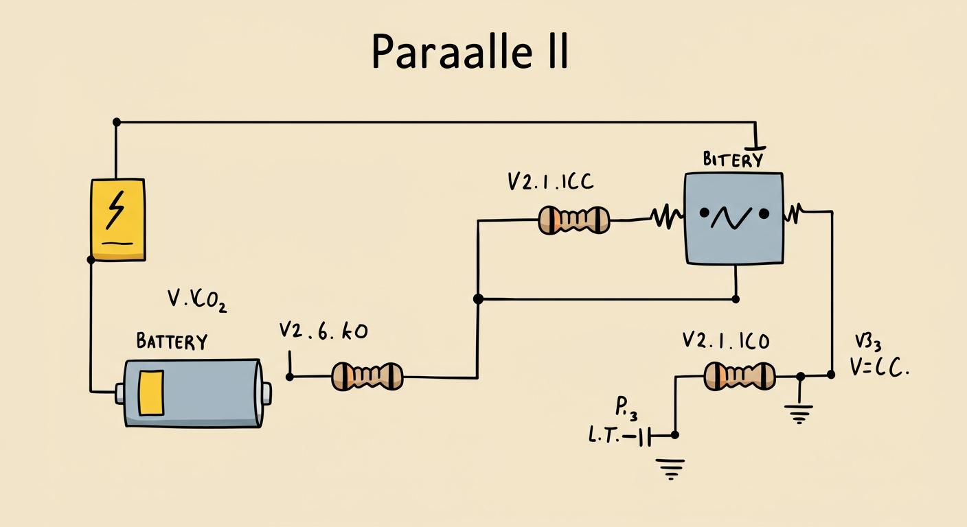
A parallel circuit provides multiple paths for current. This parallel design is common in parallel resistance circuits found in everyday technology.
- Household Wiring: Every light and outlet in a home is part of a parallel circuit, allowing each to work independently.
- Automotive Systems: A car's headlights and dashboard lights are wired in parallel to ensure they all receive the same voltage.
The foundational parallel resistor formula calculates the equivalent resistance: 1/R_Total = 1/R1 + 1/R2 + .... A simpler formula for a parallel combination of two resistors in parallel is the product-over-sum rule: R_Total = (R1 * R2) / (R1 + R2). This shortcut helps find the equivalent total resistance in a parallel resistor circuit.
💡 Key Principle: The total resistance for resistors connected in parallel is always less than the smallest individual resistor in the parallel combination. The parallel circuit's equivalent value is always smaller.
Key Takeaways
- Parallel circuits offer many paths for electricity. This design is common in homes and cars.
- Adding more resistors in parallel makes the total resistance lower. This is because more paths help electricity flow easier.
- You can find the total resistance using simple math. For two resistors, multiply them and divide by their sum. For many resistors, use reciprocals.
- In a parallel circuit, the voltage is the same across all parts. However, the electricity divides among the different paths.
- If one part of a parallel circuit breaks, the other parts usually keep working. This is a key benefit of parallel circuits.
APPLYING THE PARALLEL RESISTOR FORMULA
Understanding the theory is the first step. Now, it is time to apply these formulas to practical examples. Calculating the total resistance in a parallel circuit becomes straightforward with the right method. Different scenarios call for different formulas, from the general-purpose reciprocal method to convenient shortcuts. Each method helps determine the equivalent opposition to current flow in a parallel resistor circuit.
THE GENERAL FORMULA
The most versatile tool is the general parallel resistor formula. This formula works for any number of resistors in parallel. It is based on the principle of reciprocals.
What is a reciprocal? In mathematics, the reciprocal of a number is simply 1 divided by that number. For example, the reciprocal of 5 is 1/5. In electronics, this concept is part of a larger principle of reciprocity, where inputs and outputs in some circuits can be interchanged without changing the outcome. For our calculation, we focus on the simple mathematical definition.
Let's walk through an example. Imagine a parallel circuit with three resistors:
- R1 = 20 Ω
- R2 = 30 Ω
- R3 = 60 Ω
Step-by-Step Calculation:
- Write the formula:
1/R_Total = 1/R1 + 1/R2 + 1/R3 - Substitute the resistor values:
1/R_Total = 1/20 + 1/30 + 1/60 - Find a common denominator (in this case, 60) and add the fractions:
1/R_Total = 3/60 + 2/60 + 1/601/R_Total = 6/60 - Simplify the fraction:
1/R_Total = 1/10
⚠️ Common Mistake Alert! A frequent error is stopping here and stating the total resistance is 1/10 Ω. The calculation gives you the reciprocal of the total resistance. You must perform one final step. Forgetting to invert this final sum is a common mistake that leads to an incorrect answer.
- Invert the result to find the final total resistance:
R_Total = 10/1 = 10 Ω
The final equivalent resistance of this parallel combination is 10 Ω. Notice this value is smaller than the smallest individual resistor (20 Ω), confirming the key principle of a parallel circuit. This example shows how to calculate total resistance for multiple resistors in parallel.
CALCULATING TWO RESISTORS IN PARALLEL
When a parallel circuit contains only two resistors, a faster method exists. The "product-over-sum" formula is a popular shortcut used for quick analysis and troubleshooting. It is especially useful when designing a parallel resistor circuit to achieve a specific equivalent resistance that is not available as a standard component.
This formula is: R_Total = (R1 * R2) / (R1 + R2)
Let's use this for a new example with two resistors in parallel:
- R1 = 40 Ω
- R2 = 60 Ω
Calculation using the shortcut:
- Multiply the two resistance values (Product):
40 * 60 = 2400 - Add the two resistance values (Sum):
40 + 60 = 100 - Divide the product by the sum:
R_Total = 2400 / 100 = 24 Ω
The total resistance is 24 Ω. This equivalent value is found much faster than by using the reciprocal method for this simple parallel combination. This example demonstrates the convenience of the product-over-sum formula.
THE RULE FOR IDENTICAL RESISTORS
The simplest scenario of all involves a parallel circuit with multiple identical resistors. When all resistors in parallel have the same value, the calculation for total resistance becomes incredibly easy.
The formula is: R_Total = R / n
- R is the resistance of one of the identical resistors.
- n is the number of identical resistors in the parallel circuit.
Here is a quick example. Consider a parallel circuit with four identical 80 Ω resistors.
- R = 80 Ω
- n = 4
Applying the rule:
R_Total = 80 / 4 = 20 Ω
The equivalent total resistance is 20 Ω. This simple division provides the final answer instantly. This rule is a powerful mental shortcut for any technician or hobbyist working with a parallel combination of equivalent resistors. This final example completes our look at the main calculation methods.
WHY PARALLEL RESISTANCE DECREASES
The idea that adding more resistors lowers the total resistance can seem counterintuitive. However, the reason is simple. A parallel circuit creates more pathways for the electric current to travel. This distribution of current is the key to understanding the decrease in overall opposition.
MORE PATHS FOR CURRENT FLOW
Each new resistor added in parallel opens up another lane for electricity. This process effectively increases the total area through which current can flow. Think of it like water moving through pipes. A single pipe has a certain flow capacity. Adding a second parallel pipe allows more water to pass through the system for the same amount of pressure. In electronics:
- Adding parallel branches is like increasing the cross-sectional area of a wire.
- This larger equivalent area allows more electricity to flow.
- The total resistance changes because these areas add up, providing an easier path.
This concept explains why the equivalent resistance of a parallel combination is always smaller than the smallest individual resistor. The parallel circuit provides multiple routes, reducing the overall difficulty for the current.
THE CHECKOUT LANE ANALOGY
A great way to visualize this effect is the checkout lane analogy. Imagine a supermarket with only one checkout lane open. A long line of customers forms, creating a bottleneck. This line represents high resistance. Now, the manager opens several more checkout lanes in parallel. The customers (current) can now spread out among the different lanes. This action allows more people to check out simultaneously, drastically reducing the overall wait time. Adding more parallel lanes reduces the total opposition, letting more customers flow through the system. This is an equivalent model for a parallel circuit.
INTRODUCING CONDUCTANCE
Another way to understand parallel circuits is by using the concept of conductance. Conductance (G) is the exact opposite of resistance. It measures how easily current can flow through a material. Its unit is the Siemens (S).
Conductance and Resistance The relationship is a simple reciprocal one:
G = 1 / R. Therefore, a high resistance means low conductance, and a low resistance means high conductance.
For resistors in parallel, calculating total conductance is very straightforward. You simply add the conductance of each parallel path:
G_Total = G1 + G2 + G3 + ...
Once you find the total conductance, you can easily find the equivalent total resistance by taking the reciprocal again:
R_Total = 1 / G_Total
This method shows that each parallel path adds to the overall ease of flow, which is why the equivalent total resistance for the parallel combination must decrease.
UNDERSTANDING THE PARALLEL CIRCUIT
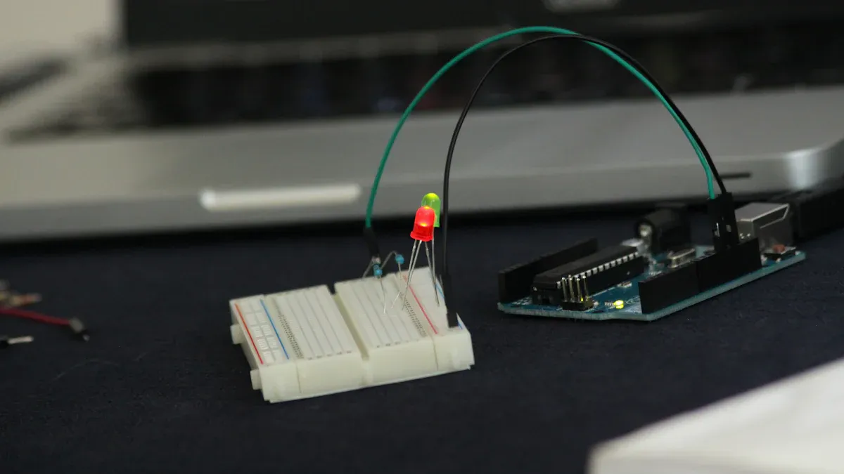
Calculating resistance is only part of the story. A deeper understanding of a parallel circuit reveals its unique electrical behaviors. The two defining characteristics of any parallel circuit are its constant voltage and divided current paths. These principles govern how the circuit operates.
CONSTANT VOLTAGE ACROSS COMPONENTS
A fundamental rule of a parallel circuit is that the voltage is the same across every component. Each resistor in a parallel arrangement connects directly to the same two nodes of the power source. This direct connection ensures there are no other components in between to cause a voltage drop. As a result, the potential voltage drop across each parallel component is equivalent to the full voltage supplied by the source. This holds true regardless of the number of parallel branches.
💡 Key Takeaway: In any parallel circuit, all components receive the full source voltage. If a 12-volt battery powers a parallel circuit, every resistor in that circuit has 12 volts across it.
DIVIDED CURRENT PATHS
While voltage remains constant, the current does not. The total current leaving the power source divides among the available paths. This behavior is described by Kirchhoff's Current Law (KCL).
- KCL states that the total current entering a junction must equal the total current leaving it.
- This means the source current is the sum of the currents in each individual parallel branch.
I_Total = I1 + I2 + ... - Current divides inversely to resistance. The path with the least resistance will carry the most current.
This principle of conservation of charge explains how a parallel combination distributes electricity. A greater current will always flow through the path of least resistance.
USING OHM'S LAW
Ohm's Law (V = IR) is essential for analyzing a parallel resistor circuit. One can calculate the total current by first finding the circuit's equivalent resistance. Let's see an example with a 12V source and a parallel combination of two resistors.
Problem: A parallel circuit has a 5 Ω resistor and a 10 Ω resistor. A 12V source powers the circuit. What is the total current?
-
Calculate Total Equivalent Resistance (R_Total): Use the product-over-sum formula for two parallel resistors.
R_Total = (R1 * R2) / (R1 + R2)R_Total = (5 * 10) / (5 + 10) = 50 / 15 ≈ 3.33 ΩThe equivalent resistance is approximately 3.33 Ω. -
Apply Ohm's Law for Total Current (I_Total): Rearrange the formula to
I = V / R.I_Total = 12V / 3.33 Ω ≈ 3.6 A
The total current drawn by this parallel circuit is approximately 3.6 Amps.
This guide covered the essential parallel resistor formula. A parallel circuit follows two fundamental rules. First, voltage remains constant across all parallel components. Second, the overall resistance is always less than the smallest individual resistor. The table below summarizes the key differences from a series circuit.
| Circuit Type | Total Resistance Calculation | Relationship to Individual Resistances |
|---|---|---|
| Series | Sum of individual resistances | Greater than any individual resistance |
| Parallel | Reciprocal of total resistance is the sum of reciprocals | Smaller than the smallest individual resistance |
Ultimately, a parallel circuit works because it offers multiple parallel paths for current. Adding more parallel resistors creates more lanes for electricity, which is why the opposition to flow in a parallel parallel circuit decreases.
FAQ
What happens if one resistor in a parallel circuit fails?
If a resistor in a parallel circuit fails by opening, it simply removes that path. The other parallel branches continue to operate normally. The total resistance of the circuit increases because there is one less path for the current to follow.
Why does the product-over-sum rule only work for two resistors?
This shortcut is a mathematical simplification of the general formula for a two-resistor parallel network. Applying it to more than two resistors at once produces an incorrect result. For three or more resistors, one must use the general reciprocal formula.
What happens when you add another resistor to a parallel circuit?
Adding another resistor to a parallel circuit creates an additional path for current. This action always decreases the total equivalent resistance of the circuit. More paths make it easier for the total current to flow from the source.
Does each branch in a parallel circuit have the same current?
⚡ No, the current is not always the same. Current divides among the branches. The branch with the lowest resistance will draw the most current. A parallel circuit with identical resistors, however, will have equal current in each path.