Discover How an Optocoupler Photocoupler Works Instantly
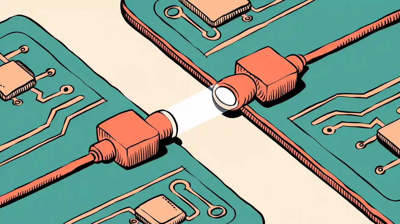
You use an optocoupler photocoupler when you want to send a signal between two circuits without letting electricity pass directly. This device works by shining light from one side to the other, keeping the circuits safely separated. People often call it an optocoupler, photocoupler, or optoisolator—they all mean the same thing. You see these terms in different places, as shown below:
| Feature | Optoisolator | Optocoupler |
|---|---|---|
| Definition | Electrical isolation by light | Optical signal coupling |
| Focus | Isolation, safety, immunity | Signal transfer |
| Use | Safety-critical fields | Consumer electronics |
Optocoupler and photocoupler sales reached $3.6 billion worldwide in 2024, showing how important these devices have become.
Key Takeaways
- Optocouplers use light to send signals between circuits while keeping them electrically isolated. This protects sensitive electronics from high voltage spikes.
- The main components of an optocoupler are a light-emitting diode (LED) and a photodetector. The LED converts electrical signals into light, and the photodetector converts light back into electrical signals.
- Optocouplers help prevent ground loops and electrical noise, ensuring clear signal transmission. They are essential in applications like audio equipment and data communication.
- These devices are widely used in consumer electronics, industrial controls, and medical equipment, providing safety and reliability in various systems.
- When choosing an optocoupler, consider factors like voltage rating, speed, and signal type to ensure it meets your circuit's needs.
Optocoupler Photocoupler Basics
What Is It?
You can think of an optocoupler photocoupler as a tiny bridge that lets signals cross safely between two electronic circuits. This device uses light to carry information instead of direct electrical contact. You often see the terms optocoupler, photocoupler, and optoisolator used for the same type of device. Each one works by converting an electrical signal into light, sending that light across an insulating barrier, and then turning it back into an electrical signal on the other side.
Tip: Optocoupler photocoupler devices help protect sensitive electronics from dangerous voltage spikes.
Here are the most common types you might find in electronics:
| Type | Description |
|---|---|
| Optocouplers | Semiconductor devices that use optical links to couple signals while providing electrical isolation. |
| Photocouplers | Often used interchangeably with optocouplers, typically contained in a single housing. |
| Opto-isolators | Used for transmitting information at higher voltage potentials, above 5,000 volts. |
| Solid State Relays | Used for switching higher power levels, often containing additional circuitry for protection. |
Inside an optocoupler, you usually find a light-emitting diode (LED) and a photodetector. The LED shines light when it receives a signal. The photodetector picks up this light and creates a new signal for the next circuit. A resin barrier keeps the two sides electrically separated.
| Device Type | Internal Structure Description |
|---|---|
| Optocoupler | Contains a LED and a light-detector element in the same package, insulated by resin, with signals switched ON/OFF by the LED. |
| Digital Isolator | Comprises a modulation chip with insulating film and a demodulation chip, transmitting signals via a magnetic or electric field. |
Main Function
You use an optocoupler photocoupler to keep two circuits isolated while still allowing signals to pass between them. This isolation helps prevent electrical noise and interference from damaging sensitive parts. The device works by turning an electrical signal into light, sending that light across a barrier, and then changing it back into an electrical signal.
- The input signal activates the LED, which emits light.
- The photodetector receives the light and generates a new signal.
- The insulating barrier keeps the circuits separate, improving safety.
| Component | Function |
|---|---|
| Light-Emitting Diode (LED) | Modulates the input signal to emit light. |
| Photodetector | Detects the emitted light and generates an output signal. |
| Insulating Barrier | Provides electrical isolation between input and output circuits. |
You often use optocouplers to connect circuits with different ground levels. This setup prevents ground loops, which can cause unwanted interference. Optocouplers also help suppress electrical noise, making them important for devices like analog-to-digital converters (ADCs).
- Optocouplers facilitate signal transmission between circuits that have separate grounds, ensuring isolation through a galvanic barrier.
- They help prevent ground loops, which can cause interference in equipment that drives remote loads.
- They suppress electrical noise effects, enhancing the performance of sensitive components like ADCs.
The PC817 optocoupler photocoupler uses an infrared LED and a phototransistor to transfer signals without direct contact. This design protects your equipment from high-voltage spikes and keeps your circuits safe.
How Optocoupler Photocoupler Works
Step-by-Step Process
You can understand the operation of an optocoupler photocoupler by following a clear sequence. This process helps you see how a signal travels from one side to the other without any direct electrical connection.
-
Input Circuit Design
You start by choosing the right resistor values for your circuit. R1 controls the current for the LED, and R2 sets the load for the phototransistor. These values help the device work safely and efficiently. -
LED Activation
When you apply an input signal, the LED inside the optocoupler photocoupler lights up. The LED changes the electrical signal into light. -
Light Transmission
The light travels across a small gap inside the device. This gap keeps the input and output circuits separate. -
Photosensor Detection
On the other side, a photosensor, such as a phototransistor, detects the light. The photosensor converts the light back into an electrical signal. -
Current Transfer Ratio (CTR)
You need to check the current transfer ratio. CTR tells you how much output current you get for a given input current. This step ensures your circuit meets the needs of your application. -
Output Signal Generation
The output circuit receives the new electrical signal. The two circuits remain electrically isolated. -
Testing and Adjustment
You test your circuit to make sure it works as expected. If needed, you adjust the resistor values to improve performance.
Tip: The response time of an optocoupler depends on the type of photosensor and the resistor values you choose. For example, a 4N25 optocoupler can switch signals in just a few microseconds. The turn-on and turn-off times depend on the LED drive current and the load resistance.
Electrical Isolation
Electrical isolation is the main reason you use an optocoupler photocoupler. This feature keeps your input and output circuits completely separate. You can even use different power supplies for each side. This separation protects your sensitive electronics from high voltage spikes and electrical noise.
- Optoisolators keep different parts of your circuit separate while still letting signals pass through.
- They protect microcontrollers and other delicate components from dangerous voltage surges.
- You often find optocouplers in power supplies and industrial control systems.
One of the primary advantages of optocouplers is their ability to provide electrical isolation. This isolation is vital for protecting sensitive components from high voltages and surges in other parts of the circuit.
Standard optocouplers can handle isolation voltages up to 8000 V. Some models, like the OPI110, can even withstand up to 15,000 V for short periods. This high level of protection makes optocoupler photocoupler devices a smart choice for safety-critical applications.
You can rely on electrical isolation to prevent high-voltage spikes or noise from damaging your equipment. This feature helps you build safer and more reliable electronic systems.
Optocoupler Components
LED
You find the LED on the input side of an optocoupler. When you send an electrical signal to the LED, it lights up. The brightness of the LED matches the strength of your input signal. This process changes electricity into light. The LED acts as the bridge that starts the signal transfer. You control the LED by adjusting the current in your circuit. The LED works quickly and reliably, making it a key part of the optoisolator.
The LED is the first step in keeping your circuits safe. It sends light instead of electricity, which helps prevent dangerous voltage spikes.
Photodetector
The photodetector sits on the output side. This photosensitive device watches for light from the LED. When the LED glows, the photodetector picks up the light and turns it back into an electrical signal. You see different types of photodetectors in optocouplers, each with its own job:
- Transistor output optocouplers use phototransistors for signal isolation.
- Thyristor or triac output optocouplers control AC power.
- Logic-level optocouplers switch digital signals quickly.
- High-voltage optocouplers handle strong isolation voltages.
- Linear optocouplers send analog signals.
- PhotoDarlington optocouplers boost current.
- PhotoMOS optocouplers use MOSFETs for solid-state switching.
The response time of the photosensor matters. Faster response times let your optocoupler follow input signals more closely. For example, a rise time of 20 microseconds and a fall time of 17 microseconds allow the output to track changes quickly. You can use optocouplers for signals up to 200 kHz.
Working Together
You see the LED and photodetector working as a team. First, the input current powers the LED, which glows with brightness that matches your signal. Next, the photodetector catches the light and creates a small current. Some optocouplers use extra circuits to make this current stronger. This teamwork lets you send signals between circuits without any direct electrical connection.
The LED and photodetector work together to keep your input and output circuits separate. You get reliable signal transfer and strong electrical isolation.
You use an optocoupler or optoisolator when you need to protect sensitive electronics. The LED and photosensor make sure your signals cross safely, even in noisy or high-voltage environments.
Optocoupler Uses
Circuit Protection
You rely on optocouplers to keep your circuits safe from electrical hazards. These devices act as shields, blocking dangerous voltage spikes and surges. When you use an optocoupler, you separate control circuits from high-voltage sections. This separation helps prevent damage to sensitive components, such as microcontrollers and digital chips. You often see optocouplers in switching power supplies, where they create a barrier between the control side and the high-voltage output. Motor control systems also benefit from optocouplers, which protect logic circuits from sudden voltage changes during motor operation.
Tip: Optocouplers help you avoid costly repairs by stopping electrical shocks before they reach your delicate electronics.
Signal Transfer
You use optocouplers to send signals between different parts of your system without letting electrical noise interfere. These devices keep signals clear and strong, even when circuits have separate ground levels. Optocouplers prevent ground loops, which can cause unwanted noise and signal distortion. In audio equipment, optocouplers maintain sound quality by blocking interference. Data communication systems also depend on optocouplers to keep signals reliable.
| Evidence Description | Impact on Signal Integrity |
|---|---|
| Protect against electrical hazards and improve noise immunity. | Maintain signal integrity in systems with different ground potentials. |
| Prevent noise-induced distortions that degrade performance. | Preserve signal integrity for effective data communication. |
| Provide galvanic isolation and reduce ground loop effects. | Enhance overall signal quality and reliability in data transmission systems. |
| Eliminate ground loops and reduce electromagnetic interference (EMI). | Ensure signals remain clear and undistorted, critical for high-precision designs. |
| High-speed optocouplers improve transmission speeds. | Increase reliability and performance in communication infrastructure. |
Common Applications
You find optocouplers in many everyday devices and advanced systems. These devices play a key role in consumer electronics, industrial controls, and medical equipment. Here are some common uses:
- Smartphones use optocouplers for safe signal isolation.
- Tablets rely on optocouplers for high-speed data transfer.
- Wearable technology depends on optocouplers for reliable operation.
- Smart devices and home automation systems need optocouplers to connect safely.
- Battery management systems use optocouplers to separate control electronics from high battery voltages.
- Medical devices require optocouplers to protect patients from electrical risks.
- PC communications, such as RS-232 or USB interfaces, use optocouplers to safeguard connections.
- Industrial control systems use optocouplers to prevent ground loops and interference.
You see optocouplers everywhere, from your phone to complex factory machines. These devices help you build safer, more reliable electronics every day.
Optocoupler Advantages
Isolation
You get strong electrical isolation when you use optocouplers. This means you can separate two circuits and still send signals between them. Optocouplers use light to transfer information, so electricity never crosses the gap. You protect your sensitive electronics from high voltages and surges. You also avoid ground loops, which can cause problems in your system.
- Optocouplers offer electrical isolation.
- You maintain signal integrity.
- You gain noise immunity.
- You enjoy higher reliability.
- You benefit from faster switching times.
- You use less power.
Optocouplers work well with simple DC signals. You find them small and affordable. Transformers, on the other hand, are larger and cost more. They only work with AC signals, so they are less flexible for logic circuits.
Safety
You rely on optocouplers to keep your devices safe. These components meet strict safety standards in many industries. You see optocouplers in medical equipment, industrial motor drives, and communication systems. They pass tough tests to make sure they provide reliable isolation.
| Standard | Description |
|---|---|
| IEC 60747-5-5 | Reliable isolation, tested under stress. |
| UL 1577 | North American safety, includes insulation tests. |
| IEC 61800 | Motor drives, recognizes IEC 60747-5-5. |
| IEC 60950 | IT and communication equipment, uses IEC 60747-5-5. |
| IEC 60601 | Medical equipment, highlights optocoupler safety. |
| IEC 61010 | Test and measurement equipment, includes safety requirements. |
You trust optocouplers to protect both people and equipment. You reduce the risk of electric shock and damage.
Noise Reduction
You use optocouplers to keep your signals clean. These devices block electrical interference and keep your data steady. You protect sensitive parts from high-voltage spikes and noise. In high-frequency circuits, optocouplers help you maintain clear communication.
- Optocouplers minimize electrical interference.
- You keep transmitted signals clear and steady.
- You shield sensitive components from spikes and noise.
Tip: You improve the reliability of your system when you choose optocouplers for noise reduction.
You now know that an optocoupler, or photocoupler, lets you send signals safely between circuits using light. This device uses an LED and a photodetector to keep your electronics protected and reliable. You find optocouplers in many places:
- Audio equipment for clear sound.
- Medical devices for safe monitoring.
- Data communication for strong signals.
- Battery management for safety and efficiency.
- Industrial automation for secure control.
| Benefit | Application Example |
|---|---|
| Noise reduction | Audio systems |
| Safety | Medical monitoring |
| Data integrity | Communication networks |
| Circuit protection | Battery management |
You help shape the future of electronics by choosing optocouplers. New designs bring digital optocouplers and better safety features. Start looking for optocouplers in your projects and enjoy safer, smarter technology! 🚀
FAQ
What is the difference between an optocoupler and a photocoupler?
You see no difference. Both names describe the same device. Manufacturers use different terms, but the function stays the same. Optocoupler, photocoupler, and optoisolator all mean a device that uses light to transfer signals safely.
Can you use optocouplers for both analog and digital signals?
You can use optocouplers for both types. Some models work best with digital signals, while others handle analog signals. Always check the datasheet to match the optocoupler to your signal type.
Tip: Choose a linear optocoupler for analog signals.
How do you test if an optocoupler works?
You connect the input side to a power source and the output side to a simple circuit. If the output responds when you send a signal to the input, your optocoupler works. Use a multimeter to check voltage changes.
Where do you find optocouplers in everyday devices?
You find optocouplers in power supplies, audio equipment, computers, and medical devices. They protect sensitive parts and keep signals clean. You also see them in smart home systems and battery management.
| Device Type | Optocoupler Role |
|---|---|
| Power supply | Circuit isolation |
| Audio system | Noise reduction |
| Medical device | Patient safety |
What should you consider when choosing an optocoupler?
You look at voltage rating, speed, and signal type. Make sure the optocoupler matches your circuit’s needs. Check the datasheet for isolation voltage and response time.
Note: Higher isolation voltage means better protection for your electronics.