L298N Motor Driver Pinout and Wiring Made Simple for Your Projects
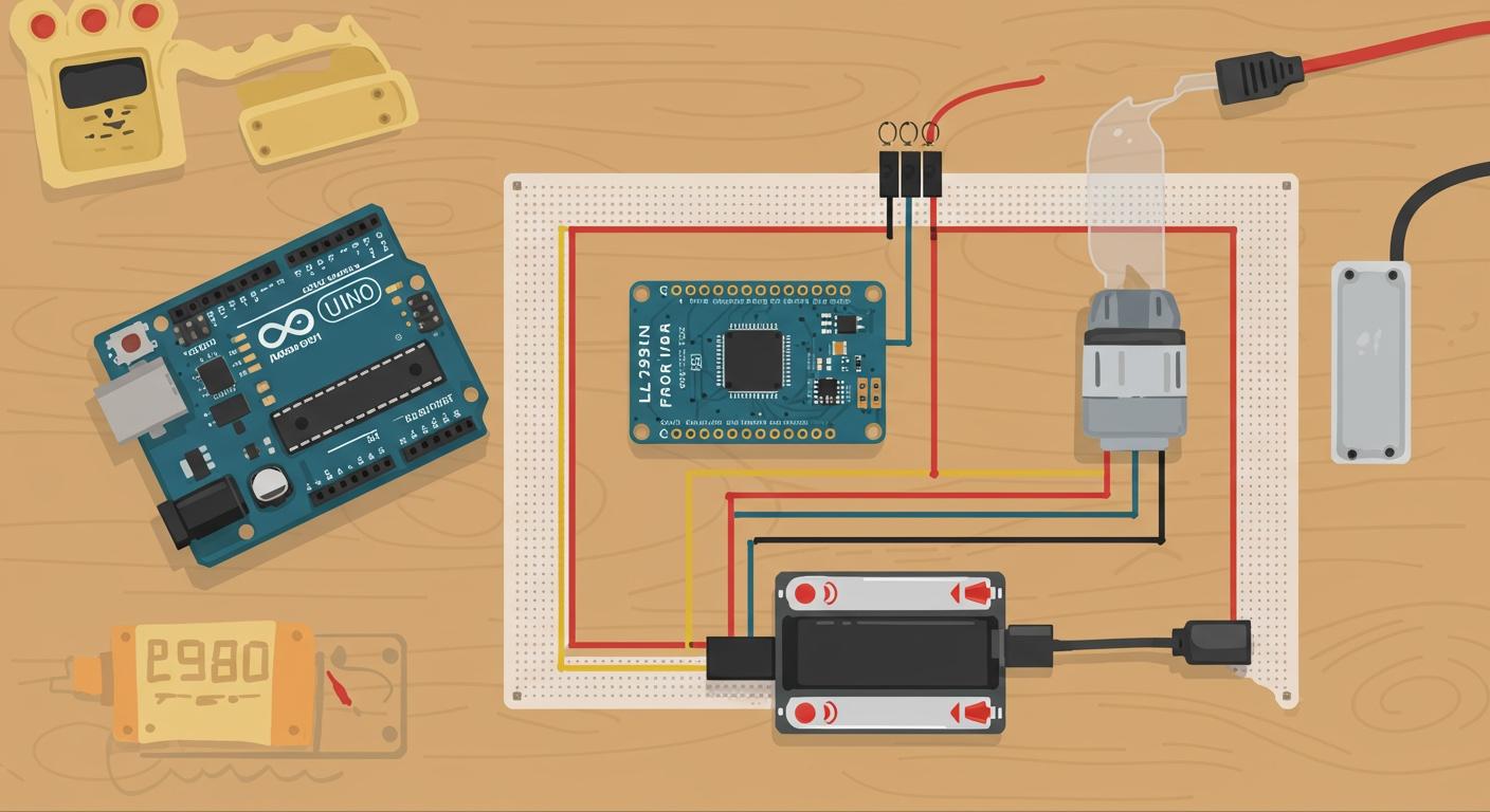
[Image: A large, clearly labeled diagram of the L298N motor driver module with all pins and terminals identified.]
This table breaks down the function of all the important pins on the l298n module.
| Pin Name | Pin Function |
|---|---|
| VCC | This pin powers the motor. |
| GND | This is the common ground connection for the module. |
| 5V | This pin can supply or receive 5V for the logic circuits. |
| IN1, IN2 | These pins control the direction of Motor A. |
| IN3, IN4 | These pins control the direction of Motor B. |
| ENA | This pin enables and controls the speed of Motor A. |
| ENB | This pin enables and controls the speed of Motor B. |
| OUT1, OUT2 | These terminals connect to Motor A. |
| OUT3, OUT4 | These terminals connect to Motor B. |
This powerful l298n motor driver is surprisingly affordable; for example, you can find it for around ₹189.00. Understanding its pins is the first step to successful motor control. This guide simplifies the wiring for the l298n module. You will learn how each of the module's pins works. These pins connect your power, microcontroller, and motor. Mastering these pins gives you complete control.
Key Takeaways
- The L298N motor driver controls two motors. It lets you change their direction and speed.
- Connect the L298N's ground pin to your microcontroller's ground pin. This makes sure all parts of your circuit work together.
- Use the ENA and ENB pins with PWM signals to control motor speed. This gives you smooth control.
- Check the 5V jumper based on your motor's power supply. This protects the module from damage.
- Always double-check your wiring. Common mistakes include wrong power, missing jumpers, or bad ground connections.
Anatomy of the L298N Motor Driver
The heart of the l298n motor driver is a powerful chip called the L298. This chip contains a dual H-bridge circuit. An H-bridge is an electronic circuit that lets you switch the polarity of the voltage applied to a load. The "dual" part means this module has two of these H-bridge circuits, so you can control two motors at the same time. This dual H-bridge setup gives you excellent motor control capabilities.
- Independent Motor Control: You can manage the direction and speed of two motors separately.
- Direction Reversal: The H-bridge circuit easily reverses a motor's direction by flipping the voltage polarity.
- Speed Control: You can adjust motor speed using a technique called Pulse Width Modulation (PWM).
Another key component on the board is the 78M05 voltage regulator. This small part provides a stable 5V to power the module's logic circuits. You will learn more about its role in the power section. Let's break down the three main groups of pins on the l298n module.
The Power Input Pins
You must correctly wire the power input pins to make your l298n motor driver work. These three pins manage all the electricity for the module and your motors.
- VCC: This is the main power supply for the motor. You connect your external power source here. This pin accepts a wide voltage range, typically from 5V to 35V.
- GND: This is the common ground pin. You must connect it to the ground of your microcontroller and your motor power supply.
- 5V: This pin powers the logic chip on the module. It can act as an input or an output depending on your setup. If your motor power supply (VCC) is 12V or less, this pin can output 5V to power your microcontroller. If your motor supply is over 12V, you must provide a separate 5V input to this pin to avoid damaging the onboard regulator.
The Motor Output Terminals
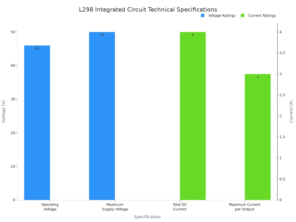
The module features two blue screw terminal blocks for connecting your motors. These are the motor output pins. One block is for Motor A (OUT1, OUT2) and the other is for Motor B (OUT3, OUT4). The L298N IC at the core of the module is quite robust. It can handle a continuous current of 2A per channel, which is enough for most hobbyist motors.
The L298N motor driver module contains two screw terminal blocks, one for each motor. You simply loosen the screws, insert the motor wires, and tighten them for a secure connection.
The L298 IC itself has impressive specifications that make this module so useful. The chart below shows its key ratings.
The Control and Enable Pins
These pins are your direct line of communication from the microcontroller to the motor. They give you precise control over each motor's behavior. The control pins are divided into two types: direction control pins and enable pins.
The direction control pins are IN1, IN2, IN3, and IN4.
IN1andIN2control the direction of Motor A.IN3andIN4control the direction of Motor B.
These pins work with standard 5V logic levels. You send a HIGH signal (5V) or a LOW signal (0V) from your microcontroller to these pins to make the motor spin forward, backward, or stop.
The enable pins are ENA and ENB. These pins give you control over the motor's speed.
ENAenables and controls the speed of Motor A.ENBenables and controls the speed of Motor B.
By sending a Pulse Width Modulation (PWM) signal to these pins, you can vary the motor's speed. The speed is directly proportional to the duty cycle of the PWM signal. This capability is essential for projects that require more than just on/off control.
| Signal on Enable Pin | Motor State |
|---|---|
| HIGH | Motor enabled at full speed |
| LOW | Motor disabled (stops spinning) |
| PWM | Motor enabled: speed changes with duty cycle |
Mastering these control pins is the key to unlocking the full potential of the H-bridge for your robotics projects.
Power Supply Wiring
Properly wiring the power supply is the most critical step to get your project moving safely. You need to provide power for two different parts of the l298n motor driver: the motors themselves and the logic chip that provides control. Let's look at how to connect the power pins correctly.
Connecting Motor Power
You must first choose the right power supply for your motor. Check your motor's datasheet for its recommended voltage and current ratings. A motor will draw more current under load, so your power supply must handle this demand.
You can connect your external power source to the VCC and GND screw terminal pins.
- Wall Adapters: These are great for stationary projects and often come in 12V versions.
- Battery Packs: These are perfect for mobile robots. You can use AA batteries in series or a LiPo battery pack.
Tip 💡: Always choose a power supply that can provide slightly more voltage and current than your motor needs. This gives you a safety margin and ensures reliable performance.
Powering the Logic Circuit
The logic chip on the l298n module needs a stable 5V supply to operate. The module includes an onboard 5V voltage regulator to help with this. This regulator can take the higher voltage from your motor power supply (VCC) and step it down to a clean 5V for the logic circuits. This feature simplifies your wiring in many common scenarios. The 5V pin on the module is directly related to this regulator's function.
The Role of the 5V Jumper
You will find a small jumper next to the power pins. This jumper controls the onboard 5V regulator and is extremely important for the safe operation of the module. Your motor power supply voltage determines whether you should keep it on or remove it.
-
Keep Jumper ON: If your motor power supply is 12V or less, you should leave the jumper on. This enables the onboard regulator. The module will create its own 5V, and the 5V pin will act as an output. You can even use this pin to power your Arduino.
-
Remove Jumper OFF: If your motor power supply is more than 12V, you must remove the jumper. This disables the onboard regulator, protecting it from damage. The 5V pin now becomes an input. You must connect a separate, regulated 5V power source to this pin to power the logic for motor control.
Correctly setting this jumper ensures your l298n motor driver and other components are protected.
Connecting to a Microcontroller
You have the power sorted out. Now you can connect the l298n motor driver to your microcontroller's brain. This wiring gives you precise motor control. You will use digital output pins from your microcontroller to send signals to the control pins on the L298N module.
Wiring the Direction Pins (IN1-IN4)
The direction control pins (IN1, IN2, IN3, IN4) tell your motors which way to spin. You connect these four pins directly to any of the digital I/O pins on your microcontroller, like an Arduino. These direction control pins give you simple forward and reverse control.
For example, you can connect the pins for Motor A like this:
IN1on the module connects to Digital Pin 8 on the Arduino.IN2on the module connects to Digital Pin 7 on the Arduino.
Setting these direction control pins to HIGH (5V) or LOW (0V) determines the motor's movement. This gives you direct control over the motor's behavior. The direction control pins are your primary tool for basic motor control.
Wiring the Enable Pins for Speed Control
The ENA and ENB pins are your speed control pins. These pins let you turn each motor on or off and, more importantly, control its speed. For full speed, you connect these pins to a 5V source. For variable speed control, you must connect them to PWM-capable pins on your microcontroller.
This table shows how the input pins work together for motor control.
| IN1 | IN2 | ENA (PWM) | Motor Behavior |
|---|---|---|---|
| LOW | LOW | HIGH | Brake (stops quickly) |
| HIGH | LOW | PWM | Rotates Forward (speed depends on PWM) |
| LOW | HIGH | PWM | Rotates Backward (speed depends on PWM) |
| HIGH | HIGH | HIGH | Brake (stops quickly) |
| - | - | LOW | Coast (stops freely) |
This level of control is essential for robotics projects. The enable pins give you nuanced control over your machine.
Connecting the Grounds
Warning ⚠️: This is the most important connection! You must connect the ground (GND) pin of your l298n module to a ground (GND) pin on your microcontroller.
Electricity needs a complete loop to flow. The ground connection provides a common reference point for all the electronic signals. Without it, the control signals from your microcontroller's pins have no return path. The module will not understand the commands from the control pins. This can lead to unpredictable motor behavior or the system not working at all. A shared ground ensures all parts of your circuit speak the same electrical language, giving you reliable control.
Project: L298N Motor Driver Arduino Control
You have learned the theory. Now it is time to build a real project. This section combines everything you have learned. You will wire the components and write code to achieve complete motor control. This hands-on experience will solidify your understanding of the l298n motor driver arduino setup.
The Complete Wiring Diagram
A clear wiring diagram is your best friend for any electronics project. It shows you exactly where each wire goes. For this project, you can find excellent Fritzing diagrams online that show the complete setup. These diagrams often translate the official datasheets into a visual guide.
Your goal is to connect the Arduino, the l298n module, one DC motor, and an external power supply. Follow the diagram carefully to connect all the power, ground, and control pins.
Heads Up! Common Wiring Mistakes 🧐 A single wrong connection can stop your project from working. Double-check your work to avoid these common errors:
- Incorrect Power Supply: Using a power source that cannot provide enough voltage or current for your motor will lead to poor performance or overheating.
- Missing Jumper Caps: Forgetting the jumper cap on the ENA pin will prevent the motor from turning on. You need this for basic on/off control.
- Improper Grounding: You must create a common ground. The ground from your Arduino, your module, and your motor power supply must all be connected.
- Incorrect Control Pin Connections: Mixing up the IN1, IN2, or ENA pins will cause the motor to behave unexpectedly or not at all.
Basic Arduino Code for Direction
With your circuit wired, you can now give it instructions. You will write a simple Arduino program to control the motor's direction. The code first tells the Arduino which pins you are using. Then, it sends signals to those pins to make the motor spin forward, backward, and stop.
The setup() function runs once when you power on the Arduino. Inside setup(), you use the pinMode() command. This command configures your chosen Arduino pins as OUTPUT pins. This setup prepares the pins to send control signals to the l298n module.
This basic code gives you simple direction control.
// Define the Arduino pins connected to the L298N
const int ENA = 9; // Enable pin for Motor A (must be a PWM pin)
const int IN1 = 8; // Direction control pin 1
const int IN2 = 7; // Direction control pin 2

void setup() {
  // Set all the motor control pins as outputs
  pinMode(ENA, OUTPUT);
  pinMode(IN1, OUTPUT);
  pinMode(IN2, OUTPUT);
}

void loop() {
  // --- Spin Forward ---
  // Set direction to forward
  digitalWrite(IN1, HIGH);
  digitalWrite(IN2, LOW);
  // Turn the motor on at full speed
  digitalWrite(ENA, HIGH);
  delay(2000); // Run forward for 2 seconds

  // --- Brake ---
  // Set both direction control pins LOW to brake the motor
  digitalWrite(IN1, LOW);
  digitalWrite(IN2, LOW);
  delay(1000); // Brake for 1 second

  // --- Spin Backward ---
  // Set direction to backward
  digitalWrite(IN1, LOW);
  digitalWrite(IN2, HIGH);
  // The motor is already enabled, so it will start spinning
  delay(2000); // Run backward for 2 seconds

  // --- Brake ---
  // Set both direction control pins LOW to brake the motor again
  digitalWrite(IN1, LOW);
  digitalWrite(IN2, LOW);
  delay(1000); // Brake for 1 second
}
In the loop() function, you use digitalWrite() to send HIGH or LOW signals to the direction control pins. This logic gives you direct control over the motor's movement.
Code for Speed Control
Simple on-off control is useful, but true motor control requires managing speed. You can achieve this using Pulse Width Modulation (PWM). Instead of just turning the enable pin HIGH or LOW, you send a PWM signal to it using the analogWrite() function.
The analogWrite() function takes a value from 0 to 255.
analogWrite(ENA, 0);tells the motor to stop.analogWrite(ENA, 127);tells the motor to run at about half speed.analogWrite(ENA, 255);tells the motor to run at full speed.
This next program demonstrates how you can make the motor slowly speed up and then slow down. This smooth control is perfect for robotics.
// Define the Arduino pins connected to the L298N
const int ENA = 9; // Enable pin for Motor A (must be a PWM pin)
const int IN1 = 8; // Direction control pin 1
const int IN2 = 7; // Direction control pin 2

void setup() {
  // Set all the motor control pins as outputs
  pinMode(ENA, OUTPUT);
  pinMode(IN1, OUTPUT);
  pinMode(IN2, OUTPUT);

  // Set the motor to spin forward
  digitalWrite(IN1, HIGH);
  digitalWrite(IN2, LOW);
}

void loop() {
  // Ramp up speed from 0 to 255
  for (int speed = 0; speed <= 255; speed++) {
    analogWrite(ENA, speed);
    delay(10); // Small delay to see the speed change
  }

  // Ramp down speed from 255 to 0
  for (int speed = 255; speed >= 0; speed--) {
    analogWrite(ENA, speed);
    delay(10); // Small delay to see the speed change
  }

  delay(1000); // Wait for a second before repeating
}
This code gives you fine-grained control over the motor's speed. You now have all the tools you need for advanced motor control in your projects.
You have successfully identified the pins, wired the power, and coded your Arduino. You now have a functional setup for complete motor control. This setup gives you direction control and speed control. Your control over this module is the key to precise control. This nuanced control gives you total control over your projects. Your control journey starts now!
Use this control to build exciting projects. You can create a line-following robot or even a robotic arm. You have the control to bring your ideas to life! 🤖
FAQ
Why won't my motor turn on?
You should check three common areas. First, confirm your power supply meets the motor's needs. Second, ensure you connected all ground pins together. Finally, verify the enable pin (ENA or ENB) is HIGH or has its jumper cap on.
Can I use the L298N to control a stepper motor?
Yes, you can control one bipolar stepper motor. You connect the motor's two coils to the Motor A and Motor B outputs. This setup uses both H-bridges on the module and requires a specific stepper library for your code.
Why is my L298N module getting very hot?
The module heats up when your motor draws too much current, typically over 2A per channel. The heatsink helps dissipate this heat. You should always check that your power supply and motor specifications are compatible with the driver's limits.
What is the difference between brake and coast?
These two actions stop your motor in different ways.
Brake: You actively stop the motor by setting both direction pins (e.g., IN1 and IN2) to the same logic level. This causes a quick, sharp stop. Coast: You simply disable the output by setting the enable pin LOW. The motor will spin down freely without any braking force.