A Simple Guide to Inductance and Capacitance
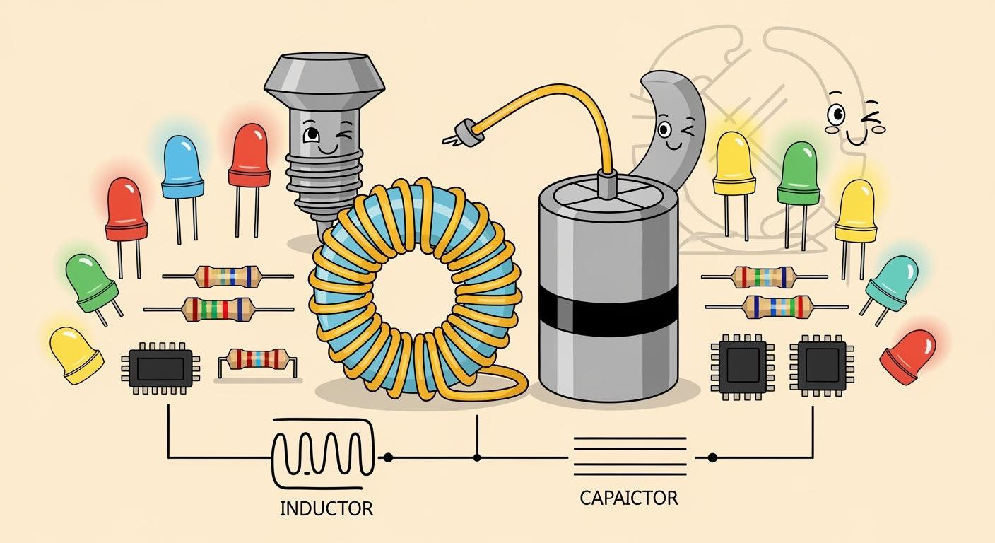
This capacitors and inductors review starts with a core distinction. Capacitance stores energy in an electric field, resisting voltage changes. In contrast, inductance stores energy in a magnetic field to oppose current changes.
Analogy Time! 💡 Think of a capacitor as a small water tank that keeps pressure (voltage) steady. An inductor is like a heavy water wheel that maintains a consistent flow (current).
These components are fundamental in modern electronics, with the inductor market showing steady growth.
Metric | 2023 | 2024 | 2030 | CAGR (2024-2030) |
|---|---|---|---|---|
Global Inductor Market Size (USD Million) | 4,515.0 | 4,739.40 | 6,540.8 |
Key Takeaways
Capacitors store energy in an electric field. They keep voltage steady, like a water tank.
Inductors store energy in a magnetic field. They keep current smooth, like a heavy water wheel.
Capacitors block DC current once charged. They let AC current pass, especially high frequencies.
Inductors pass DC current easily once steady. They block AC current, especially high frequencies.
Capacitors and inductors work together in circuits. They help create things like radio tuners and filters.
What is Capacitance?
A capacitor is an electronic component with the ability to store energy within an electric field. Think of it as a small water tank that holds pressure (voltage) steady. Its main job is to resist sudden changes in voltage, ensuring stability in a circuit. The process of capacitance measurement is crucial for verifying a component's specifications.
How a Capacitor Works
A basic capacitor has a simple structure. It consists of two conductive plates separated by an insulating material called a dielectric. When a voltage is applied, the plates store an electric charge. The dielectric material between the plates enhances the capacitor's performance. Materials with a higher dielectric constant allow for more energy storage. The capacitance is determined by the plate area, the distance between them, and the type of dielectric used.
Unit of Measurement: The Farad
The standard unit for capacitance measurement is the Farad (F). One Farad is a very large unit, so you will more commonly see capacitance expressed in smaller units:
Microfarads (µF): one-millionth of a Farad.
Nanofarads (nF): one-billionth of a Farad.
Picofarads (pF): one-trillionth of a Farad.
Precise capacitance measurement is essential in circuit design. Techniques like capacitance measurement using a bridge circuit provide highly accurate readings.
Behavior with AC and DC
Capacitors behave differently depending on the type of current.
With Direct Current (DC): When first connected to a DC source, a capacitor charges up. Once it is fully charged, it blocks the flow of current. In a DC circuit, a charged capacitor acts like an open switch.
With Alternating Current (AC): In a capacitive circuit with AC, the capacitor continuously charges and discharges. It offers opposition to the current, known as capacitive reactance. This reactance decreases as the frequency of the AC signal increases. Therefore, capacitors pass high-frequency signals more easily than low-frequency ones.
Role as a High-Pass Filter
This unique behavior with AC allows a capacitor to function as a high-pass filter. A high-pass filter lets high-frequency signals pass through while blocking low-frequency signals. In audio systems, for example, a capacitor can direct high-pitched sounds to a tweeter speaker and block low-bass signals. This filtering capability is a key application of capacitance measurement and component selection.
Understanding Inductance and Its Properties
An inductor stores energy in a magnetic field when current flows through it. Its primary job is to resist sudden changes in current. This property is called inductance. Think of it as a heavy water wheel. It takes effort to get it spinning, but once it is moving, it keeps the water flow (current) smooth and steady.
How an Inductor Works
An inductor's operation relies on electromagnetic induction. A simple inductor is often a coil of wire.
Current flowing through the wire creates a magnetic field around it.
Coiling the wire concentrates this magnetic field, increasing its strength.
According to Faraday's Law, any change in this magnetic field induces a voltage that opposes the original change in current.
This process, known as self-induction, gives the component its ability to store energy and stabilize current. The induced voltage is proportional to how fast the current changes. This relationship highlights the core function of inductance in circuits.
Unit of Measurement: The Henry
The standard unit for inductance is the Henry (H), named after Joseph Henry. One Henry represents a large amount of inductance, so smaller units are more common in practice:
Millihenrys (mH): one-thousandth of a Henry.
Microhenrys (µH): one-millionth of a Henry.
Accurate inductance measurement is vital for designing effective circuits. For high-precision work, engineers often perform inductance measurement using a bridge circuit to get exact values.
Behavior with AC and DC
Inductors react very differently to direct and alternating currents.
With Direct Current (DC): When first connected, an inductor opposes the current flow. However, once the current becomes steady, the magnetic field stops changing. The inductor then acts like a simple piece of wire, or a short circuit, offering no resistance.
With Alternating Current (AC): In an inductive circuit, the current is always changing. The inductor continuously creates an opposing voltage. This opposition is called inductive reactance (XL). Reactance increases as the AC frequency increases. The formula for this is
XL = 2πƒL.
Role as a Low-Pass Filter
This behavior with AC makes an inductor a natural low-pass filter. It allows low-frequency signals (and DC) to pass through easily while blocking high-frequency signals. In an audio system, an inductor can be used to direct low-frequency bass sounds to a woofer speaker while filtering out high-pitched sounds.
Direct Comparison: Key Differences
Capacitors and inductors are fundamental electronic components. They have opposite yet complementary functions. Understanding their key differences is essential for grasping circuit behavior.
Primary Function
A component's primary function defines its role in a circuit. Capacitors and inductors serve very different purposes based on their physical construction.
Capacitor: Its main job is to resist changes in voltage. It acts like a small reservoir, keeping the voltage level stable.
Inductor: Its main job is to resist changes in current. It acts like a flywheel, keeping the current flow smooth.
Their construction directly enables these functions. Capacitors are built with two metallic plates, such as tantalum or aluminum, separated by a dielectric material. In contrast, inductors are constructed from a coil of wire wound around a core material.
Feature | Capacitor | Inductor |
|---|---|---|
Primary Goal | Stabilize Voltage | |
Construction | Two conductive plates and a dielectric | A coil of wire around a core |
Energy Storage Method
Both components store energy, but they do so in different fields. This difference is central to their behavior. A capacitor's ability to store energy comes from an electric field. An inductor's inductance allows it to store energy in a magnetic field.
The energy stored in a component is related to the strength of its field.
The energy density in a capacitor is proportional to the square of the electric field strength (E). Similarly, the energy density in an inductor is proportional to the square of the magnetic field strength (B).
This means a stronger field holds more energy. The capacitor holds this energy in the space between its plates. The inductor holds its energy in the space surrounding its coil.
Response to DC
Direct Current (DC) is a steady, one-way flow of electricity. Capacitors and inductors react to DC in opposite ways after an initial period.
Capacitor: When first connected to DC, a capacitor charges up. Once fully charged, it completely blocks the flow of DC. It acts like an open switch.
Inductor: When first connected to DC, an inductor opposes the initial surge of current. Once the current is steady, the inductor passes it without opposition. It acts like a simple wire or a short circuit.
Response to AC
Alternating Current (AC) constantly changes direction. This continuous change causes capacitors and inductors to behave very differently than they do with DC. They both create opposition, called reactance.
A key concept in AC circuits is the phase relationship between voltage and current.
A helpful mnemonic is "ELI the ICE man".
ELI: In an inductor (L), voltage (E) leads current (I). The current lags behind the voltage.
ICE: In a capacitor (C), current (I) leads voltage (E). The voltage lags behind the current.
For a capacitor, current must flow first to build up charge on its plates. This charge creates the voltage. For an inductor, the changing magnetic field (caused by current) induces a voltage that opposes the current change. This property of inductance causes the current to lag.
Circuit Symbol
Engineers use standard symbols in circuit diagrams to represent components. The symbols for capacitors and inductors reflect their basic structure.
Component | Symbol | Description |
|---|---|---|
`─ | ||
Capacitor (Polarized) | `─ | curved_line ─` |
Inductor (Air Core) |
| A series of loops represents the coil of wire. This symbol shows the inductor has no special core material. |
Inductor (Iron Core) |
| The loops with a solid line above them signify a core made of iron or another ferromagnetic material to increase the inductance. |
Practical Roles in Everyday Electronics
Capacitors and inductors are not just theoretical concepts. They are essential workers inside the devices people use every day. Their opposite behaviors make them powerful tools for controlling electricity.
Common Uses for Capacitors
Capacitors excel at storing and releasing energy quickly. This makes them perfect for a variety of tasks.
Power Supply Filtering: In electronic devices, capacitors act as noise filters. They provide a low-impedance path for high-frequency noise, guiding it away from sensitive integrated circuits. They also serve as small, local power reservoirs, supplying extra current during sudden demand to prevent voltage drops.
Camera Flashes: A camera flash needs a powerful burst of energy. A photoflash capacitor stores a high-voltage charge from the battery over several seconds. When the picture is taken, it discharges all that energy in a fraction of a second to power the bright flash.
Common Uses for Inductors
An inductor’s ability to resist changes in current makes it ideal for signal filtering and energy storage in magnetic fields. The property of inductance is crucial for these applications.
Example: Radio Tuning 📻 In a radio tuner, an inductor and a variable capacitor form a resonant circuit. This circuit is tuned to resonate at the specific frequency of a desired radio station. It allows that frequency to pass while rejecting others, letting you hear one station clearly. An inductive circuit is fundamental to this selection process.
How They Work Together
Capacitors and inductors often work as a team. Their most important partnership is in an LC circuit, also known as a tank circuit. In this setup, energy moves back and forth between the two components.
The capacitor stores energy in an electric field.
It discharges, creating a current that flows through the inductor.
The inductor stores the energy in a magnetic field.
The magnetic field collapses, creating a current that recharges the capacitor.
This continuous exchange of energy creates an electrical oscillation. This principle is the foundation for creating radio waves in transmitters and keeping time in electronic clocks.
Capacitors and inductors serve opposite yet essential roles. A capacitor stabilizes voltage, while an inductor stabilizes current. Their distinct behaviors are easy to remember with a simple image.
Final Analogy 💧 A capacitor acts like a water tank, keeping pressure (voltage) steady. An inductor acts like a heavy water wheel, keeping the flow (current) smooth.
These components have opposing functions. This opposition makes them perfect partners. They work together to ensure electronic circuits operate correctly and efficiently.
FAQ
What happens if a capacitor is connected backward?
Polarized capacitors have positive and negative terminals. Connecting one backward can cause it to fail. The capacitor might overheat, leak, or even burst. Non-polarized capacitors can be connected in either direction without issue.
Why are inductors usually coils?
Inductors are coils of wire. This shape concentrates the magnetic field created by the current. A stronger, more concentrated magnetic field results in higher inductance. The core material inside the coil can increase this effect even more.
How are capacitance and inductance measured?
Technicians use special tools for measurement. A digital lcr meter is a common device. It accurately measures a component's inductance (L), capacitance (C), and resistance (R), ensuring it meets design specifications.
Do capacitors and inductors consume power?
Ideal capacitors and inductors do not consume power. They only store and release energy. However, real-world components have internal resistance. This resistance causes a small amount of energy to be lost as heat.