How to Use an Accelerometer Sensor with Arduino
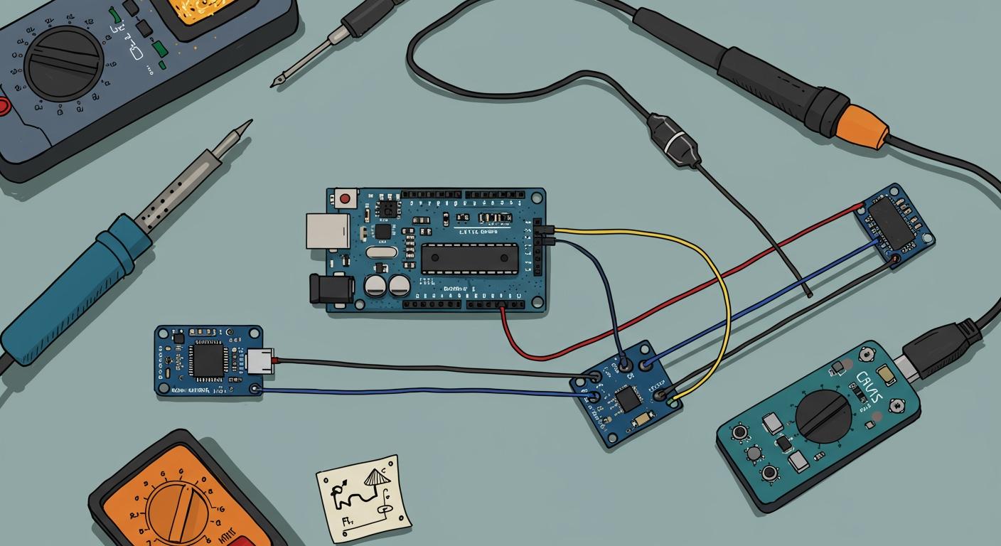
Have you ever wanted your Arduino project to sense motion, tilt, or orientation? You can easily achieve this using an accelerometer sensor. This project is a fantastic and rewarding first step into the world of motion sensing with Arduino.
You're in good company! 🧑💻 You are joining a massive global community of over 30 million active Arduino users. This supportive group makes getting started easier than ever. In 2023 alone, contributors added 1,068 new libraries, providing powerful and ready-to-use code for your projects.
Key Takeaways
- You can use an MPU-6050 accelerometer sensor with Arduino to sense motion and tilt.
- Connect the MPU-6050 to Arduino using four wires for power, ground, and data communication.
- Install specific libraries in the Arduino IDE to help your Arduino talk to the sensor.
- Upload a simple code to your Arduino to read and display the sensor's motion data.
- Visualize sensor data using the Serial Plotter or an OLED screen to see how it moves.
GATHERING YOUR COMPONENTS
Before you can start sensing motion, you need to collect a few key items. This section lists all the hardware and software required for this project. Having everything ready will make the process smooth and enjoyable.
REQUIRED HARDWARE
You will need a handful of electronic components for this project. Most of these are common in the Arduino world and easy to find.
- Arduino Uno: This microcontroller board will be the brain of our operation.
- MPU-6050 Module: This is the star of the show. The MPU-6050 is a powerful and affordable accelerometer sensor.
- It contains a 3-axis accelerometer and a 3-axis gyroscope.
- It uses a 16-bit Analog-to-Digital Converter (ADC) for precise measurements.
- Breadboard: A solderless breadboard helps you connect components without permanent soldering.
- Jumper Wires: You will use these to connect the sensor to your Arduino.
You can purchase these parts from many online electronics suppliers. For example, Adafruit offers an MPU-6050 sensor (Product ID: 3886) that is compatible with 5V Arduino boards. You can also find components at global distributors like DigiKey Electronics, Mouser Electronics, Pimoroni, and Core Electronics.
REQUIRED SOFTWARE
The only software you need is the official Arduino Integrated Development Environment (IDE). You will use the IDE to write the code, compile it, and upload it to your Arduino board. It works on Windows, macOS, and Linux.
You can find the latest version of the Arduino IDE on the official website. Make sure you download the correct version for your operating system from:
https://www.arduino.cc/en/software
With your components and software ready, you are prepared for the next step: wiring!
WIRING THE ACCELEROMETER SENSOR
Now you will connect your components. This step is crucial, but it is also very straightforward. You will link the MPU-6050 accelerometer sensor to your Arduino Uno using just four wires. This connection allows the two devices to communicate.
UNDERSTANDING THE SENSOR PINS
First, you should get familiar with the pins on your MPU-6050 module. Each pin has a specific job. Understanding them helps you wire everything correctly.
- VCC: This pin supplies power to the sensor. You will connect it to the 5V pin on your Arduino.
- GND: This is the ground pin. It completes the electrical circuit.
- SCL: This is the Serial Clock pin. It helps synchronize data transfer between the sensor and the Arduino.
- SDA: This is the Serial Data pin. It carries the actual measurement data from the sensor to the Arduino.
- INT: This is the Interrupt pin. You can program it to send a signal when the sensor detects specific movements like a tap or shake. We will not use this pin in this basic guide.
CONNECTING TO YOUR ARDUINO
You will use the I2C communication protocol to connect the sensor. This protocol is great because it only requires two wires for data (SDA and SCL). Follow this wiring guide to connect your MPU-6050 to your Arduino Uno.
| MPU-6050 Pin | Arduino Uno Pin |
|---|---|
| VCC | 5V |
| GND | GND |
| SCL | A5 |
| SDA | A4 |
Pro Tip 💡: Keep your jumper wires as short as possible. For very short connections, you can use shielded cables for the SDA and SCL wires to protect the signal from electrical noise. This simple practice helps ensure you get clean and reliable data from your sensor.
Double-check your connections. A correct wiring setup is key to a successful project. With your hardware now connected, you are ready to move on to the software setup!
SETTING UP THE ARDUINO IDE
Your hardware is connected, but it needs instructions to work. You will now add special code "libraries" to your Arduino IDE. Libraries are bundles of pre-written code that save you from writing everything from scratch. They make it much easier to communicate with complex components like your accelerometer sensor.
INSTALLING THE MPU6050 LIBRARY
First, you need a library specifically for the MPU-6050. This library contains all the commands to initialize the sensor and read its data. While Adafruit provides an excellent official library for their version of the sensor, we will use a popular and easy-to-use alternative for this guide.
This is the Adafruit MPU6050 6-DoF Accelerometer and Gyro Library for Arduino. You can find its source code on GitHub at
https://github.com/adafruit/Adafruit_MPU6050.
You can install the required library directly from the Arduino IDE. Follow these simple steps:
- Open your Arduino IDE.
- Navigate to the Library Manager by going to
Sketch>Include Library>Manage Libraries.... - In the search bar, type
MPU6050. - Find the library named "MPU6050 by Electronic Cats" and click the "Install" button.
INSTALLING THE SENSOR LIBRARY
Some sensor libraries, including the one from Adafruit, depend on a helper library. This helper is the Adafruit Unified Sensor Driver. You need to install it for our code to work correctly.
To install it, search for "Adafruit Unified Sensor" in the Library Manager and click "Install." With both libraries installed, your IDE is now ready for the code.
CODING YOUR ARDUINO
With your hardware wired and your IDE prepared, you are ready for the most exciting part: writing the code. The code, or "sketch," is the set of instructions that tells your Arduino what to do. You will write a sketch to read data from the MPU-6050 and send it to your computer.
THE COMPLETE ARDUINO SKETCH
For those who want to get straight to it, here is the complete Arduino sketch. You can copy and paste this code directly into your Arduino IDE. We will break down what each part does in the following sections.
// Include the necessary libraries
#include <Adafruit_MPU6050.h>
#include <Adafruit_Sensor.h>
#include <Wire.h>

// Create an object for the MPU6050 sensor
Adafruit_MPU6050 mpu;

void setup(void) {
  // Start serial communication to send data to the computer
  Serial.begin(9600);

  // Check if the MPU-6050 sensor is connected
  if (!mpu.begin()) {
    Serial.println("Failed to find MPU6050 chip");
    while (1) {
      delay(10);
    }
  }
  Serial.println("MPU6050 Found!");

  // Set the accelerometer measurement range
  // Options: MPU6050_RANGE_2_G, MPU6050_RANGE_4_G, MPU6050_RANGE_8_G, MPU6050_RANGE_16_G
  mpu.setAccelerometerRange(MPU6050_RANGE_8_G);

  Serial.println("---------------------------------");
}

void loop() {
  // Create special variables to hold sensor data
  sensors_event_t a, g, temp;

  // Get new sensor readings
  mpu.getEvent(&a, &g, &temp);

  // Print the acceleration values for the X, Y, and Z axes
  Serial.print("Accel X: ");
  Serial.print(a.acceleration.x);
  Serial.print(" m/s^2, ");

  Serial.print("Y: ");
  Serial.print(a.acceleration.y);
  Serial.print(" m/s^2, ");

  Serial.print("Z: ");
  Serial.print(a.acceleration.z);
  Serial.println(" m/s^2");

  // Pause for a moment before the next reading
  delay(500);
}
Looking for more code examples? 🧑💻 The official Arduino community offers a wealth of resources. You can find alternative sketches for reading raw MPU-6050 values and other helpful information at the Arduino Playground:
http://playground.arduino.cc/Main/MPU-6050
CODE: LIBRARIES AND OBJECTS
The first few lines of your sketch are essential for setting things up. They tell the Arduino which tools it needs to use.
#include <Adafruit_MPU6050.h>
#include <Adafruit_Sensor.h>
#include <Wire.h>
These #include lines add the libraries you installed earlier. The Wire.h library is built into the Arduino IDE and handles I2C communication.
Next, you create an object to represent your sensor.
Adafruit_MPU6050 mpu;
This line creates an instance of the Adafruit_MPU6050 class, which we name mpu. Think of this as giving your physical sensor a name in the code. The Adafruit_MPU6050() constructor prepares this object to manage all communication with the accelerometer sensor.
CODE: THE SETUP FUNCTION
The setup() function runs only once when your Arduino first powers on. You use it to initialize settings and prepare your components.
-
Start Serial Communication:
Serial.begin(9600);The
Serial.begin(9600)command activates the serial hardware on your Arduino. It sets a communication speed of 9600 bits per second (baud). This step is crucial. It allows your Arduino to send data to your computer so you can see the sensor readings in the Serial Monitor. -
Initialize the Sensor:
if (!mpu.begin()) {
  Serial.println("Failed to find MPU6050 chip");
  while (1) {
    delay(10);
  }
}
Here,
mpu.begin()tries to establish a connection with the MPU-6050. This function is vital because it checks that the sensor is wired correctly and responding. If the Arduino cannot find the sensor, it will print an error message and enter an infinite loop, preventing the program from continuing with a faulty connection. -
Set the Accelerometer Range:
mpu.setAccelerometerRange(MPU6050_RANGE_8_G);The MPU-6050 can measure acceleration across different ranges. You use the
setAccelerometerRange()function to choose one. A smaller range provides more sensitive readings, while a larger range can measure more intense movements.MPU6050_RANGE_2_G: For very sensitive tilt measurements (±2g).MPU6050_RANGE_4_G: A good middle ground (±4g).MPU6050_RANGE_8_G: For projects involving moderate motion (±8g).MPU6050_RANGE_16_G: For high-impact or fast-motion projects (±16g).
CODE: THE LOOP FUNCTION
The loop() function runs over and over again after setup() is complete. This is where you will continuously read data from the sensor.
-
Get Sensor Data:
sensors_event_t a, g, temp;
mpu.getEvent(&a, &g, &temp);
First, you declare three
sensors_event_tvariables. These are special containers designed by the Adafruit Unified Sensor library to hold sensor data. Then, you callmpu.getEvent(). This function requests the latest measurements from the MPU-6050 and fills your variables with acceleration, gyroscope, and temperature data. -
Access and Print Values:
Serial.print("Accel X: ");
Serial.print(a.acceleration.x);
To access the raw acceleration values, you use
a.acceleration.x,a.acceleration.y, anda.acceleration.z. The code then prints these values to the Serial Monitor with labels, so you can easily identify them. -
Add a Delay:
delay(500);The
delay(500)function pauses the program for 500 milliseconds (half a second). This is important "blocking code." It stops all other execution, which prevents your Arduino from flooding the Serial Monitor with data too quickly. This pause makes the output much easier to read.
UPLOADING AND TESTING
Now you will send your code to the Arduino board.
- Connect Your Arduino: Plug your Arduino Uno into your computer using the USB cable.
- Select Board and Port: In the Arduino IDE, go to
Tools>Boardand make sure "Arduino Uno" is selected. Then, go toTools>Portand choose the correct serial port for your board. - Upload the Sketch: Click the upload button (the right-pointing arrow icon) in the top-left corner of the IDE.
The IDE will compile your code and upload it. If everything is correct, you will see a "Done uploading" message.
Having trouble uploading? 🧰 Don't worry, it happens! An error message like
Failed uploading: uploading error: exit status 1can occur if the Serial Monitor is already open. Other common issues include:
Programmer Not Responding: This often means you have selected the wrong board or port, or the USB cable is loose.Permission Denied: This error can happen on Linux systems if the IDE does not have permission to access the USB port.Invalid Device Signature: This indicates a mismatch between the board selected in the IDE and the actual board you are using.
Once your code is uploaded, your Arduino is officially reading data from the MPU-6050! The next step is to see that data in action.
VISUALIZING DATA WITH THE SERIAL PLOTTER
Reading numbers in the Serial Monitor is useful, but seeing your data visually can reveal so much more. The Arduino IDE has a built-in tool called the Serial Plotter. It turns the stream of numbers from your sensor into a live graph. This makes it incredibly easy to see how your sensor responds to movement in real time.
OPENING THE SERIAL PLOTTER
You can access the Serial Plotter with just a few clicks. It uses the same connection as the Serial Monitor, so you can only have one open at a time.
- Make sure your Arduino is connected to your computer.
- Close the Serial Monitor window if it is open.
- In the Arduino IDE, navigate to the menu bar.
- Click on
Tools>Serial Plotter.
A new window will pop up, and you will see three colored lines start to draw across the screen. Each line represents one of the accelerometer's axes: X, Y, and Z.
INTERPRETING THE LIVE GRAPH
The graph you see shows the acceleration forces acting on your sensor. When your sensor is perfectly still and flat on a table, you might expect the lines to be at zero. However, you will see that one line is not at zero.
What are you seeing? 🌍 That steady line represents the constant pull of Earth's gravity! When the sensor is stationary, it primarily measures gravity. This makes the accelerometer an excellent tool for determining orientation. The device's posture changes which axis aligns with the gravitational pull.
Try tilting your sensor. You will see the values on the graph change immediately.
- When the sensor is flat, the Z-axis (often the blue line) will show a value of approximately -9.8 m/s², which is equal to -1g. The X and Y axes will be near 0.
- If you rotate the board 90 degrees, you will see the Z-axis line move toward zero while another axis (X or Y) moves toward -9.8.
The relative values of the three lines on the graph give you a clear picture of the sensor's orientation. You are visually tracking how the sensor is positioned relative to the force of gravity.
DISPLAYING DATA ON AN OLED
The Serial Plotter is great, but what if you want a portable project? You can add a small screen to display your accelerometer data without needing a computer. You will now learn how to connect a common 0.96" I2C OLED display and update your code to show the live readings.
WIRING THE OLED DISPLAY
You will be happy to know that the OLED display uses the same I2C communication protocol as your MPU-6050 sensor. This means you can connect both devices to the same two pins on your Arduino! You just need to connect the display's power, ground, and I2C lines.
Follow this simple wiring guide. You can connect the OLED's wires to the same rows on your breadboard that the MPU-6050's SCL and SDA pins are connected to.
| OLED Pin | Arduino Uno Pin |
|---|---|
| VCC | 5V |
| GND | GND |
| SCL | A5 |
| SDA | A4 |
I2C Explained 💡: The I2C protocol allows multiple devices to share the same two data lines (SDA and SCL). Each device has a unique address, so the Arduino knows which one it is talking to. This makes wiring complex projects much cleaner.
INSTALLING OLED LIBRARIES
Your Arduino needs new instructions to control the OLED screen. You will install two libraries from Adafruit.
- Open the Arduino IDE and go to
Sketch>Include Library>Manage Libraries.... - Search for "Adafruit GFX". Find the library named "Adafruit GFX Library" and click "Install". This is the core graphics library that lets you draw shapes, lines, and text. You can find its source code at
https://github.com/adafruit/Adafruit-GFX-Library. - Next, search for "Adafruit SSD1306". Find the library by Adafruit and click "Install". This library works as a driver, allowing your Arduino to communicate specifically with the SSD1306 chip on your OLED display. Its repository is located at
https://github.com/adafruit/Adafruit_SSD1306.
UPDATING THE CODE FOR THE DISPLAY
You must now modify your code to send data to the new screen. You will add code to initialize the display in the setup() function and then print the acceleration values inside the loop() function.
The basic process involves a few key commands:
display.begin(): Initializes the connection to the display.display.clearDisplay(): Wipes the screen clean before you draw new data.display.setTextSize(): Sets the font size.display.setCursor(x, y): Moves the "cursor" to a specific pixel coordinate.display.println(): Prints text to the screen.display.display(): Sends the new information to the screen to make it visible.
Your new loop() function will use these commands to show the X, Y, and Z values, updating them with every new reading from the sensor.
You have successfully connected an accelerometer to your Arduino. You installed libraries, wrote code to read sensor data, and visualized it on your computer and an OLED screen. This is a key skill for many electronics projects. You are now ready to build something new.
What's Next? 🚀 You can use your new skill to create amazing things. Here are a few ideas to get you started:
- Build a digital spirit level that uses the MPU-6050 to measure angles with high accuracy.
- Create a gesture control system to recognize specific movements like tilts or waves.
- Develop a posture tracker to monitor your neck and back alignment.
- Design a "Bump-O-Meter" that combines your sensor with a GPS to log and map road conditions.
FAQ
### What should I do if the Serial Monitor shows "Failed to find MPU6050 chip"?
This error usually points to a wiring issue. You should carefully check your connections.
Troubleshooting Checklist ✅
- Confirm
SDAconnects to Arduino pinA4.- Confirm
SCLconnects to Arduino pinA5.- Ensure the
VCCandGNDpins have a solid connection to 5V and GND.
### Can I use a different Arduino board, like a Nano or Mega?
Yes, you can use other Arduino boards. You must connect the sensor to the correct I2C pins for that specific board. The pins are not always A4 and A5.
| Board | SDA Pin | SCL Pin |
|---|---|---|
| Arduino Uno | A4 | A5 |
| Arduino Nano | A4 | A5 |
| Arduino Mega | 20 | 21 |
### Why do my accelerometer readings jump around so much?
Accelerometers are extremely sensitive to tiny vibrations, which can make the data appear "noisy." You can write code to average several readings. This technique smooths the data and provides a more stable output for your project.
### What is the gyroscope on the MPU-6050 used for?
The gyroscope measures how fast the sensor is rotating around each axis. While the accelerometer measures linear motion, the gyroscope measures angular motion. Combining data from both sensors gives you a much more accurate and stable understanding of the device's orientation.