A Simple Approach to Continuity Testing for New Users
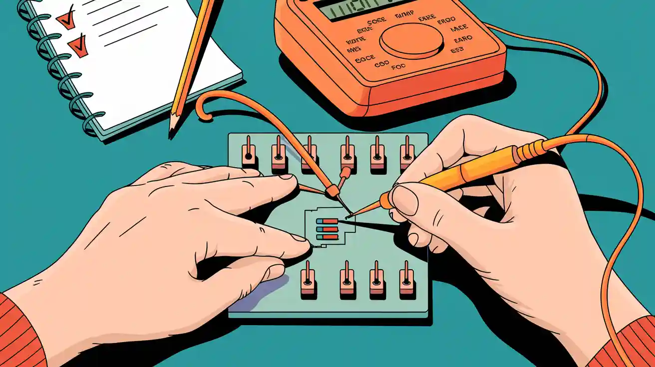
Welcome! If you feel unsure about continuity testing, you are not alone. This simple check helps you find broken paths in wires or circuits. You can use a multimeter, which is a handy tool for this job. I will show you how to use a meter to test continuity in easy steps.
Key Takeaways
- Always turn off the power before testing continuity to ensure safety and prevent damage to your multimeter.
- Use the continuity mode on your multimeter to check if a circuit path is complete; listen for a beep to confirm a good connection.
- Regularly test your probes by touching them together before each continuity check to avoid false readings.
What Is Continuity?

You might wonder what continuity means in electrical circuits. Think of it as a clear path for electricity to travel. If you picture a road, continuity is like making sure there are no gaps or broken bridges. When the path is complete, electricity flows easily. If there’s a break, nothing gets through.
- Circuit continuity is the uninterrupted path for electric current.
- You need a complete circuit for devices to work.
- Checking continuity helps you spot problems like broken wires or short circuits.
- Imagine a road with a drawbridge. If the bridge is up, cars stop. In a circuit, a break stops the current.
Why Continuity Matters
You want your devices to work safely and reliably. Testing continuity helps you do that. Here’s why it’s important:
- You can verify if the electrical path is complete.
- You find open circuits, broken wires, or bad connections.
- You keep yourself safe by avoiding shocks or short circuits.
- Troubleshooting gets easier because you can pinpoint faults.
- You follow electrical codes and keep things up to standard.
- You catch problems early, which helps with maintenance.
Tip: Always test continuity before you power up a circuit. This simple step can save you from headaches later.
Continuity in Circuits
Continuity affects how well your circuit performs. If you work with circuit boards, you need good traces for current flow, heat control, and signal quality. In high-speed circuits, keeping the path smooth prevents signal loss. A solid ground and smart signal return paths help reduce noise and keep things stable.
- Continuity testing (the “beep test”) checks if two points connect, like in switches or fuses.
- Resistance tests measure specific values in components, but continuity just tells you if the path is open or closed.
- Most digital multimeters beep when they detect continuity, making your job easier.
Multimeter Basics
Multimeter Parts
When you pick up a digital multimeter, you see a few main parts. Each part helps you test circuits safely and easily. Here’s a quick look at what you’ll find:
| Component | Description |
|---|---|
| LED Display | Shows the selected measurement and range. |
| Test Lead Ports | Where you plug in the black and red probes. Usually labeled COM, V/Ω, and A. |
| Battery | Powers the digital multimeter and sends a small current for testing. |
| Continuity Mode | Lets you check if a circuit path is complete. |
You use the LED display to read numbers and symbols. The test lead ports hold the probes you touch to the circuit. The battery gives the digital multimeter the power it needs. Continuity mode is the special setting you use for this test.
Tip: A digital multimeter is more accurate than an analog one. It gives you clear numbers, works well in low light, and often has safety features like auto-ranging.
Continuity Mode
Continuity mode is your best friend when you want to check if a wire or circuit path is complete. When you set your digital multimeter to this mode, it sends a tiny current through the circuit. If the path is good, you hear a beep and see zero or very low resistance. If the path is broken, you see a high number or the display shows “OL” (open loop).
- The digital multimeter measures resistance in continuity mode.
- You hear a beep if the resistance is low enough, which means the circuit is closed.
- Each digital multimeter may have a different beep threshold, so always check your manual.
A digital multimeter makes this process simple. You do not need to guess. You just listen for the beep or watch the display. This feature helps you find problems fast and keeps your projects safe.
How to Use a Meter to Test Continuity
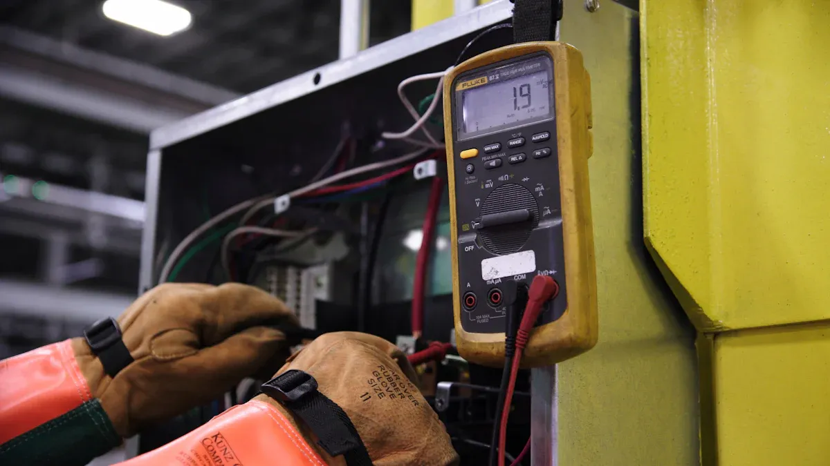
Safety First
Before you even touch your multimeter, safety comes first. You want to avoid shocks, fires, or damage to your tools. Here are some simple steps to keep you safe:
- Always turn off the power to the circuit you plan to test. Never try continuity testing on a live circuit.
- Inspect your multimeter and probes for any cracks or damage. Replace them if you see any problems.
- Assume every wire is live until you check it yourself.
- Wear safety glasses and gloves if you work in a risky area.
- Never work alone, especially in damp or hazardous places.
Here’s a quick look at common hazards:
| Safety Hazard | Description |
|---|---|
| Shock Hazards | Can happen if your meter or test leads are damaged. |
| Arc Flash Risks | Using the wrong meter for the voltage can cause dangerous flashes. |
| Voltage Transients | Sudden spikes can be risky if not managed. |
| Probe Insulation Deterioration | Cracked insulation can lead to shocks. |
| Equipment Maintenance | Always check your tools before you start testing. |
Tip: Never skip the safety check. It only takes a minute and can save you from serious harm.
Setting Up the Multimeter
Now you’re ready to set up your multimeter for continuity testing. Here’s how to use a meter to test continuity step by step:
- Insert the black test lead into the COM jack.
- Insert the red test lead into the VΩ jack.
- Turn the dial to the continuity mode. Look for a sound wave or diode symbol.
- Make sure your circuit is powered off before you connect the probes.
- Prepare your workspace. Keep your hands dry and your area clear.
If you’re testing a pcb, make sure the board is out of the circuit or powered down. This helps you get accurate results and keeps your multimeter safe.
Testing the Probes
You want to make sure your probes and meter work before you start the real test. Here’s how:
- Touch the metal tips of the probes together.
- Your multimeter should beep or show a reading close to zero (0Ω to 2Ω).
- If you don’t hear a beep or see a high number, check the probe connections or clean the tips.
- Replace the probes or battery if you still get no response.
Note: Always test your probes before every continuity check. This simple habit saves you from chasing false problems.
Preparing the Circuit
Getting your circuit ready is just as important as the test itself. Here’s what you need to do:
- Double-check that the power is off.
- Remove the component or wire from the rest of the circuit if possible. This avoids false readings from other paths.
- If you’re testing a pcb, make sure you isolate the trace or component you want to check.
Alert: Testing a live circuit can damage your multimeter and put you at risk. Always power down first.
| Danger Type | Description |
|---|---|
| Risk of Electrical Shock | Testing a live circuit can lead to lethal electric shocks. |
| Damage to the Tester/Multimeter | Continuity testers are not designed for live circuits, risking damage. |
| Fire Hazard | Short-circuiting live wires can create sparks or fire hazards. |
Performing the Continuity Test
Now you’re ready for the main event. Here’s how to use a meter to test continuity:
- Set your multimeter to continuity mode (look for the sound wave or diode symbol).
- Make sure your probes are in the correct jacks (black in COM, red in VΩ).
- Touch the probes to the two points you want to test. For example, touch both ends of a wire or across a fuse.
- Listen for a beep or watch the display.
- If you hear a beep, you have a closed circuit. Electricity can flow.
- If you see “OL” or a very high number, the path is open. No continuity.
- If you see a low number (0Ω to 2Ω), you have good continuity.
Tip: When testing a pcb, touch the probes to the trace or pad ends. This helps you find broken paths or bad solder joints.
What the Results Mean
Understanding your results is key for troubleshooting and repairs. Here’s a quick guide:
| Continuity Condition | Meter Reading | What It Means |
|---|---|---|
| No Continuity - Open Circuit | OL | The path is broken. No current can flow. |
| Full Continuity - Short Circuit | 0.2 ohms | The path is too good—could be a short. Watch out for this! |
| Good Continuity - Some Resistance | 2.3 ohms | Normal for most wires and traces. Good connection. |
| So-So Continuity - More Resistance | 10.1 ohms | Possible problem. Check for corrosion or loose connections. |
| Indeterminant Continuity | 86.7 ohms+ | Too much resistance. Not good for power circuits. |

- A beep means a closed circuit. You’re good to go.
- No beep or “OL” means an open circuit. You need to fix the break.
- Low resistance (0Ω to 2Ω) means a solid connection.
Troubleshooting
Sometimes, things don’t go as planned. Here are some common problems and how to fix them:
- No beep? Check your probe connections. Make sure the meter is in continuity mode. Inspect the probes for damage or dirt. Try a new battery if needed.
- Wrong reading? Double-check that the circuit is powered off. Make sure you’re touching the right points. Isolate the component from the rest of the pcb if possible.
- Still stuck? Try cleaning the probe tips. Look for broken wires or bad solder joints on the pcb.
- If your multimeter never beeps, even when the probes touch, you might need new probes or a new meter.
“Incorrect probe placement can lead to misleading continuity test results, especially when testing live circuits. This can cause the multimeter to provide false readings, such as indicating continuity when there is none, or vice versa. Additionally, connecting the probes incorrectly can risk damaging the multimeter.”
Here are some mistakes beginners often make:
- Using the wrong setting on the multimeter.
- Forgetting to turn off the power before testing.
- Placing the probes in the wrong jacks.
- Measuring ohms while the circuit is live (dangerous!).
- Not isolating the part of the pcb you want to test.
If you follow these steps, you’ll master how to use a meter to test continuity. You’ll find broken wires, bad connections, and fix your pcb projects with confidence. Troubleshooting gets easier every time you practice.
You just learned how to check if a circuit is complete using a multimeter. Here’s what you should remember:
- Always turn off the power before testing.
- Touch the probes together to check your meter.
- Listen for a beep to find a good connection.
- Use a checklist for every test.
| Benefit | Description |
|---|---|
| Systematic Steps | A checklist helps you cover every step and avoid missing anything. |
Keep practicing! Each test builds your confidence. Soon, you’ll want to try more multimeter features and tackle bigger projects. 😊
FAQ
What should I do if my multimeter does not beep during a continuity test?
Check your probes. Make sure you set the meter to continuity mode. Try touching the probes together. If you still get nothing, replace the battery.
Can I test continuity on a live circuit?
No, you should never test continuity on a live circuit. Always turn off the power first. This keeps you safe and protects your meter.
Why do I get a beep but still have a bad connection?
Sometimes, a weak or dirty spot lets just enough current through for a beep. Clean the area and check the connection again for a solid result.