How to Use a 2N2222 Transistor as a Switch
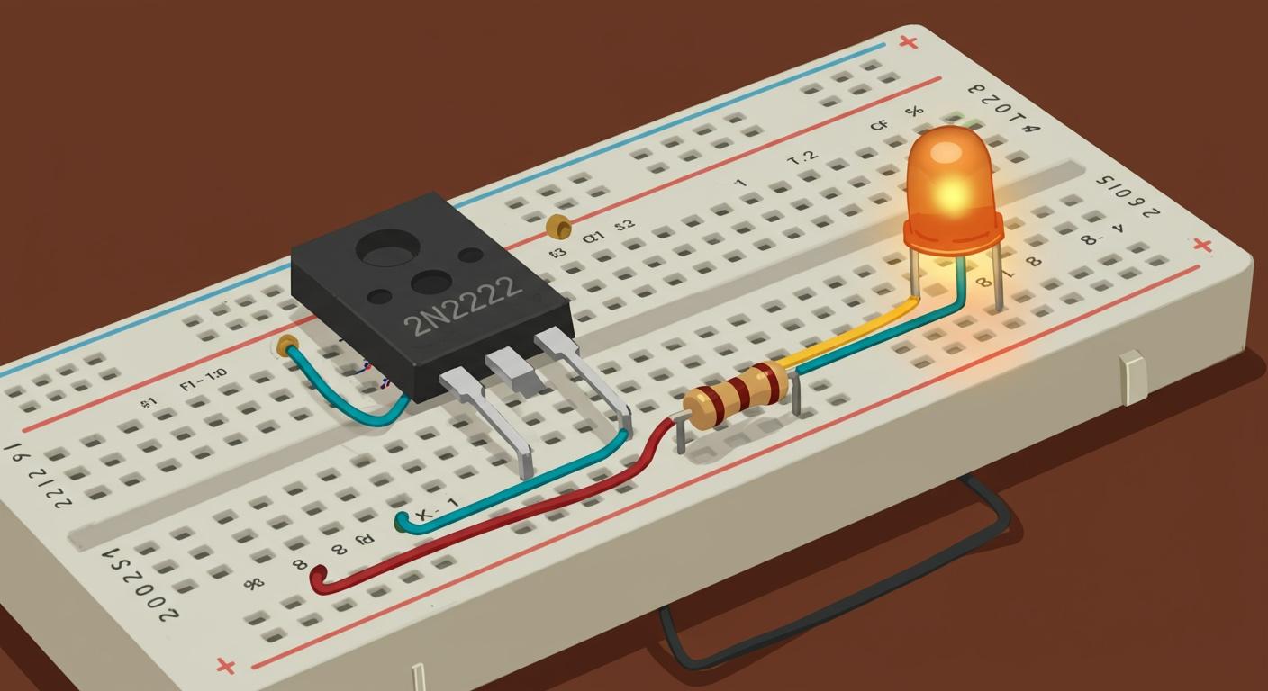
Think of the 2n2222 transistor as a tiny, electronically controlled switch 🕹️. You apply a small electrical signal to its base pin to manage a much larger current flowing from its collector to its emitter. This simple action allows you to turn a device, like an LED, on or off using a signal from a microcontroller or a simple button.
Fun Fact: This control is possible because of current gain! The current gain (hFE) for this component is generally between 100 and 300, meaning a tiny input current creates a much larger output current.
Key Takeaways
- A 2N2222 transistor acts like an electronic switch. It uses a small signal to control a larger current.
- You need specific parts to build a transistor switch. These include an Arduino, the transistor, an LED, and resistors.
- Correctly identify the transistor's pins: Emitter, Base, and Collector. This step is very important for building the circuit.
- Resistors protect your circuit. The base resistor protects the Arduino and transistor, and the collector resistor protects the LED.
- The transistor has two main states: OFF (cutoff) and ON (saturation). You control these states with a signal to the base pin.
BUILDING THE SWITCH CIRCUIT
Now you are ready to build your first transistor switch. This project uses an Arduino to send the control signal, but the principles apply to any microcontroller. We will build a "low-side switch," which is a standard and effective design for an NPN transistor.
REQUIRED COMPONENTS
Before you start, gather all the necessary parts. Having everything ready makes the assembly process smooth and fun.
- Control Source: 1x Arduino UNO (or a similar microcontroller)
- Transistor: 1x 2N2222 Transistor (in a TO-92 plastic package)
- Load: 1x Standard 5mm LED (any color)
- Resistors:
- 1x 220Ω Resistor (for the base)
- 1x 330Ω Resistor (to protect the LED)
- Power: A suitable DC power supply. You can use the Arduino's 5V output for this simple circuit, but for other projects, a 6V, 9V, or 12V supply works well.
- Prototyping:
- 1x Solderless Breadboard
- Jumper Wires
2N2222 TRANSISTOR PINOUT
Identifying the pins correctly is the most critical first step. The 2N2222A, the plastic TO-92 version of the 2n2222 transistor, has a standard pinout.
Hold the transistor with the flat side facing you and the legs pointing down. The pins are arranged from left to right:
- Emitter (E)
- Base (B)
- Collector (C)
Pro Tip 📝: While this E-B-C pinout is common, manufacturers sometimes create variants. Always double-check the official datasheet for your specific part. You can find datasheets from manufacturers like STMicroelectronics or on search engines like Alldatasheet.com.
CIRCUIT SCHEMATIC
A schematic is a map of your circuit. It shows how all the components connect electronically. Understanding these symbols will help you read any circuit diagram in the future.
| Component | Symbol | Description |
|---|---|---|
| NPN Transistor |  | The arrow on the Emitter (E) points outward. A good way to remember this is "Not Pointing iN." |
| Resistor |  | A zig-zag line represents resistance, which limits the flow of current. |
| LED |  | This is a diode symbol with two arrows pointing away, which signifies that it emits light. |
| Ground |  | This symbol indicates a common connection point for the circuit, usually 0V. |
In our NPN circuit, the arrow on the emitter points toward ground. This shows the direction of conventional current flow when the switch is on.
BREADBOARD ASSEMBLY STEPS
Let's bring the circuit to life! Follow these steps carefully. Place your breadboard in front of you and get started.
- Place the Transistor: Gently press the 2n2222 transistor into the breadboard. Make sure its three pins are in separate rows. Remember the pinout: Emitter, Base, Collector.
- Connect the Emitter to Ground: Use a jumper wire to connect the Emitter pin (the leftmost pin) to the Arduino's Ground (GND) pin. This also connects it to the breadboard's blue ground rail.
- Connect the Base Resistor: Connect the 220Ω resistor from the Base pin (the middle pin) to an empty row on the breadboard.
- Connect the Arduino Signal: Use another jumper wire to connect the other end of the 220Ω resistor to digital pin 7 on your Arduino. This pin will send the "ON/OFF" signal.
- Connect the LED:
- Connect the 330Ω resistor to the Collector pin (the rightmost pin).
- Connect the long leg (anode) of the LED to the other end of that resistor.
- Connect the short leg (cathode) of the LED to the Arduino's 5V pin.
- Power Up: Connect your Arduino to your computer via USB. The circuit is now complete!
Watch Out! Common Mistakes to Avoid ⚠️ Beginners often run into a few simple problems. Keep these in mind to ensure your circuit works on the first try.
- Improper Insertion: Make sure component legs are pushed firmly into the breadboard holes. A loose connection will prevent your circuit from working.
- Forgetting the Base Resistor: Never connect a signal pin directly to the transistor's base. The base resistor is essential to limit current and protect both the Arduino and the transistor from damage.
- Incorrect Biasing: For this NPN switch to work, the base must receive a positive voltage relative to the emitter. Our circuit achieves this by connecting the emitter to ground and the base to a positive Arduino signal.
HOW THE TRANSISTOR SWITCH WORKS
Your circuit is built, but what is actually happening inside that tiny black component? To use a transistor effectively, you need to understand its two main operating states for switching: fully "OFF" (Cutoff) and fully "ON" (Saturation). Your goal is to make the transistor jump between these two states, ignoring the area in between.
CUTOFF STATE: SWITCH OFF
Imagine a closed gate on a path. This is the transistor in its cutoff state. The switch is OFF.
This happens when you provide no voltage or current to the Base pin. In your circuit, this is when the Arduino's digital pin 7 is set to LOW (0V). With no "push" at the base, the path between the Collector and the Emitter remains blocked. No current can flow through the LED, so it stays off.
How it Works Inside 💡 For an NPN transistor, a positive voltage at the base (relative to the emitter) is needed to get things moving. When the base voltage is zero, the base-emitter junction is not forward-biased. This prevents free electrons in the N-type emitter from starting their journey toward the collector. The path is effectively an open circuit.
SATURATION STATE: SWITCH ON
Now, imagine the gate swinging wide open. This is the transistor in its saturation state. The switch is ON.
You achieve this by sending a small current to the Base pin. When you set the Arduino's digital pin 7 to HIGH (5V), current flows through the base resistor and into the transistor's base. This small base current "unlocks" the main path, allowing a much larger current to flow from the Collector to the Emitter, lighting up your LED.
The physical mechanism is quite clever:
- A positive voltage at the base forward-biases the emitter-base junction. This encourages free electrons to move from the emitter into the base region.
- The base region is extremely thin and doesn't have many "holes" for these electrons to fall into.
- Because of this, most electrons shoot right past the base and are pulled into the collector region, creating the main collector current.
- Only a tiny fraction of electrons combine in the base, which creates the small base current you provide.
This is how a small base current controls a much larger collector current. The amplification factor is called the current gain (β or hFE).
Collector Current (Ic) = Gain (β) * Base Current (Ib)
To ensure the switch is fully ON, you must provide enough base current to saturate the transistor. In saturation, the collector current is limited by your load (the LED and its resistor), not by the transistor's gain. You are effectively "overdriving" the base to guarantee the gate is as open as it can possibly be.
THE ROLE OF RESISTORS
The resistors in your circuit are not optional; they are essential safety components. They act as traffic controllers for electricity.
The Base Resistor (220Ω)
This is the most critical resistor in the circuit. It protects both your Arduino and your 2n2222 transistor.
- What it does: It limits the amount of current your Arduino pin sends to the transistor's base. The base-emitter junction of a transistor behaves like a diode. If you connect a 5V signal directly to it, it will try to draw a huge amount of current.
- What happens without it: An Arduino pin can safely provide about 20-40mA of current. Without a base resistor, the transistor could try to pull over 200mA! This would quickly overheat and destroy the output driver on the Arduino and likely burn out the transistor itself. You might even see it release its "magic smoke." 💥
Choosing the Right Value 🧰 You calculate the base resistor using Ohm's Law. You need to know the source voltage (5V from the Arduino), the voltage drop at the base (about 0.7V for silicon transistors, known as
Vbe), and the desired base current (Ib).Base Resistor = (Source Voltage - Base Voltage) / Desired Base Current
For example, to get a 20mA collector current (
Ic), you might want a base current (Ib) of about 1mA to ensure saturation.
(5V - 0.7V) / 0.001A = 4300Ω, or 4.3kΩ. Our 220Ω resistor provides much more current, pushing the transistor deep into saturation, which is perfect for a switch.
The Collector Resistor (330Ω)
This resistor's job is to protect the load—in this case, the LED. A standard LED cannot handle 5V directly. This resistor limits the current flowing through the LED when the transistor switch is ON, preventing it from burning out.
TESTING YOUR CIRCUIT
You have assembled the circuit. Now it is time for the exciting part: testing your work. This process confirms your connections are correct and demonstrates the transistor's switching action in real-time.
APPLYING POWER
You will now give your circuit the electricity it needs to operate. Follow these steps carefully to power your circuit safely.
- Double-Check Connections: Before applying power, quickly review your breadboard. Ensure the positive and negative wires go to the correct power rails. A wrong connection can cause a short circuit.
- Connect the Arduino: Plug your Arduino into your computer using its USB cable. The USB connection provides a stable 5V, which is perfect for this circuit.
- Verify Power (Optional): You can use a multimeter to test the voltage. Set your multimeter to DC voltage and touch the probes to the breadboard's 5V and GND rails. You should see a reading close to 5V.
TRIGGERING THE BASE
You will control the transistor's base using a simple program on your Arduino. This code tells digital pin 7 to switch between HIGH (5V) and LOW (0V), turning your switch on and off.
Open the Arduino IDE and upload the following code to your board:
void setup() {
  // Set digital pin 7 as an output
  pinMode(7, OUTPUT);
}

void loop() {
  digitalWrite(7, HIGH);  // Turn the transistor ON
  delay(1000);            // Wait for one second
  digitalWrite(7, LOW);   // Turn the transistor OFF
  delay(1000);            // Wait for one second
}
A microcontroller's HIGH signal, whether 5V or 3.3V, easily provides enough voltage to activate the transistor's base, which typically only needs around 0.7V to turn on.
OBSERVING THE RESULT
With the code running, you should see the LED blink. It will turn on for one second, then turn off for one second, repeating indefinitely. This shows your transistor is successfully acting as an electronic switch!
If your LED does not light up, don't worry. You can use a multimeter in diode test mode to check your 2n2222 transistor.
Troubleshooting with a Multimeter 🛠️ A healthy NPN transistor behaves like two diodes. If your readings don't match this table, the component may be damaged.
Junction Bias Expected Reading (Diode Mode) Base-Emitter Forward (Red to Base, Black to Emitter) 0.45V - 0.9V Base-Collector Forward (Red to Base, Black to Collector) 0.45V - 0.9V All Others Reverse "OL" (Over Limit)
A reading of "OL" in forward bias or a voltage drop in reverse bias indicates a faulty transistor.
Congratulations! You have successfully wired a 2n2222 transistor to create a reliable electronic switch. You now understand the core principle: a tiny input current to the base manages the main current flowing from the collector to the emitter. This simple circuit is a powerful building block for your future electronics journey.
What's Next? 🚀 Use this knowledge to control bigger loads. You can now build circuits to switch on:
FAQ
Can I use a different NPN transistor?
Yes, you can often substitute similar NPN transistors like the PN2222A or the BC547. You must always check the new transistor's pinout in its datasheet. The pin arrangement (E-B-C) can be different, so verifying it helps you avoid mistakes.
Can I control a DC motor instead of an LED?
Yes, but you need an extra component for safety. Motors create voltage spikes that can damage your transistor.
Protection Tip 🛡️ You should add a flyback diode (like a 1N4001) in parallel with the motor. This simple addition protects your circuit from harmful voltage.
Why is my LED dim?
A dim LED usually means not enough current is flowing through it. Your base resistor's value might be too high, which prevents the transistor from turning on completely. You can try a smaller base resistor to fix this issue.
Can I use a 9V battery for the load?
Absolutely! You can power your load with a separate, higher voltage supply.
- Connect the 9V battery's positive terminal to your load (e.g., the LED's resistor).
- Connect the battery's negative terminal to the circuit's common ground (the Arduino's GND pin).
This lets you control higher-power devices.