How to Understand Potentiometer Pinout for Circuit Design

A potentiometer pinout shows you the arrangement of the three pins on a potentiometer. Each pin has a specific job in your circuit. If you connect the pins incorrectly, your potentiometer will not work as you expect. When you understand the pinout, you can wire your potentiometer with confidence. This helps you control voltage or resistance in your project. You avoid mistakes and get better results with clear knowledge of the potentiometer pinout.
Key Takeaways
- A potentiometer has three pins: two fixed ends and a middle wiper that controls voltage or resistance.
- Correct wiring of pins is crucial; the middle pin is the wiper, and the outer pins connect to power and ground.
- You can use a potentiometer as a voltage divider with all three pins or as a variable resistor using two pins.
- Always check the datasheet and test with a multimeter to identify pins and avoid wiring mistakes.
- Choose a potentiometer with the right resistance, power rating, and style to fit your circuit and environment.
Potentiometer Pinout Basics
A potentiometer is a variable resistor with three pins. You use it to control voltage or resistance in many electronic circuits. Understanding the potentiometer pinout helps you connect it correctly and get accurate results.
Pin Numbering
You will find three pins on almost every potentiometer. Each pin has a standard number and function. The industry uses the same numbering for rotary, slide, and trimmer potentiometers. This makes it easier for you to read schematics and follow wiring diagrams.
Here is a table that shows the standard pinout for a typical potentiometer:
| Pin Number | Function | Description |
|---|---|---|
| 1 | Fixed End | Connected to one end of the resistive track |
| 2 | Wiper (Variable End) | Connected to the wiper, provides variable voltage |
| 3 | Fixed End | Connected to the other end of the resistive track |
Tip: Pin 2 is always the wiper. It moves along the resistive track and changes the output voltage or resistance. Pins 1 and 3 are the fixed ends. You usually connect them to the power supply and ground.
You will see this pin numbering in datasheets and on the potentiometer symbol in circuit diagrams. The potentiometer symbol often shows three pins, with the middle pin representing the wiper.
Pin Layout
The physical layout of the three pins depends on the type of potentiometer you use. Rotary potentiometers have their three pins arranged in a semi-circle. The two outer pins (1 and 3) connect to the ends of the resistive track. The middle pin (2) connects to the wiper, which rotates inside the device.
Slide potentiometers, also called faders, have their three pins in a straight line. The two end pins connect to the ends of the straight resistive track. The middle pin connects to the slider, which moves back and forth.
-
Rotary potentiometer:
- Three pins in a semi-circular pattern.
- The wiper pin is in the center.
- The potentiometer symbol for rotary types often shows a curved arrow pointing to the wiper.
-
- Three pins in a straight line.
- The slider moves along a straight path.
- The potentiometer symbol for slide types may show a straight arrow pointing to the wiper.
Here is a simple diagram to help you visualize the pinout:
Rotary Potentiometer (Bottom View)
   _______
  |       |
  |       |
  |_______|
   | | |
   1 2 3

Pin 1: Fixed End
Pin 2: Wiper (Variable End)
Pin 3: Fixed End
You will see the potentiometer symbol in circuit diagrams. It always shows three pins. The symbol helps you match the physical pins to the correct spots in your circuit.
Note: The correct potentiometer pinout ensures that your circuit works as planned. If you swap the wiper with a fixed end, the voltage or resistance will not change as you expect.
The three pins work together to form a voltage divider. When you turn the knob or move the slider, the wiper changes position. This changes the resistance between the wiper and each fixed end. You get a smooth, adjustable output. This is why the potentiometer pinout is so important for accurate analog signal control.
Identifying Potentiometer Pins
Visual Identification
You can often identify the potentiometer pinout by looking at the device itself. Most potentiometers have three pins. The two outer pins connect to the ends of the resistive track. The middle pin connects to the wiper. Here’s how you can visually locate each pin:
- Hold the potentiometer so the pins face you.
- Notice the arrangement. Rotary potentiometers usually have pins in a semi-circle. Slide potentiometers have pins in a straight line.
- The middle pin is almost always the wiper. The two outer pins are the fixed ends.
- Some potentiometers have small numbers or labels next to the pins. These markings help you match the pinout to a datasheet or circuit diagram.
Tip: If you see a flat side or a notch on the potentiometer body, use it as a reference point. Manufacturers often use these features to show pin 1.
Using Datasheets
Datasheets give you the most reliable information about the potentiometer pinout. You can find the pin numbering, layout, and even the function of each pin. Follow these steps to confirm the pinout using a datasheet and a multimeter:
- Remove the potentiometer from the circuit. This prevents false readings.
- Turn off all power to the device before testing.
- Open the datasheet for your potentiometer model. Look for a diagram showing the pinout.
- Set your multimeter to resistance (ohms) mode.
- Connect the probes to the two outer pins. The reading shows the total resistance of the potentiometer.
- Move the knob to the middle position.
- Measure between the middle pin and each outer pin. The resistance should be about half the total value if the potentiometer is linear.
- Turn the knob and watch the resistance change between the wiper and each end. The wiper pin is the one where resistance changes as you turn the knob.
- Always make sure the circuit is powered off before testing.
- Handle the potentiometer gently to avoid damage.
Note: The pinout may differ between models. Always check the datasheet and test with a multimeter to confirm the correct pinout for your potentiometer.
A careful check of the potentiometer pinout helps you avoid wiring mistakes. You get accurate control in your circuit and prevent damage to your components.
Pin Functions
Understanding the function of each pin on a potentiometer helps you wire your circuit correctly and get the results you expect. Each terminal plays a unique role in controlling voltage and resistance.
Terminal 1
Terminal 1 is the input voltage terminal of the potentiometer. You connect this pin to the power source in your circuit. When you apply a voltage here, the potentiometer can act as a voltage divider. This pin sits at one end of the resistive element inside the device.
- Terminal 1 receives the supply voltage.
- It serves as the starting point for the voltage drop across the resistive track.
- You usually connect this pin to Vcc or another positive voltage source.
If you want your potentiometer to work as a voltage divider, always connect Terminal 1 to the input voltage. This setup lets you adjust the output voltage by turning the knob or moving the slider.
Environmental factors like humidity and temperature can affect the performance of Terminal 1. Moisture or corrosion may damage the pin, so you should keep your potentiometer in a dry and stable environment.
Wiper (Terminal 2)
Terminal 2 is the wiper, which is the adjustable center pin of the potentiometer. The wiper moves along the resistive element when you turn the knob or slide the control. This movement changes the resistance between the wiper and each end terminal.
The wiper lets you control the output voltage. As you adjust its position, the resistance on either side of the wiper changes. This action divides the voltage between Terminal 1 and Terminal 3. You can use the wiper to fine-tune the output for your circuit.
The wiper is the key to making the potentiometer variable. You get precise control over the output voltage or resistance by moving the wiper.
If you connect a load to the wiper, the output voltage may change because of loading effects. The wiper resistance can reach up to one-quarter of the total potentiometer resistance, especially near the midpoint. This can cause small errors in your output.
Terminal 3
Terminal 3 is the ground or reference terminal of the potentiometer. You connect this pin to the negative side of your power supply or to ground. Terminal 3 sits at the opposite end of the resistive element from Terminal 1.
- Terminal 3 provides a reference point for the voltage divider.
- It ensures that the output voltage at the wiper varies between the supply voltage and ground.
- You should always connect this pin to ground for stable operation.
Terminal 3 acts as the anchor for your potentiometer circuit. It helps you measure and control the output voltage accurately.
When you use the potentiometer as a voltage divider, Terminal 3 is essential for setting the lower limit of the output voltage. Environmental conditions like corrosion or material breakdown can affect this pin, so choose potentiometers made from materials that resist moisture and heat.
Potentiometer Wiring Examples
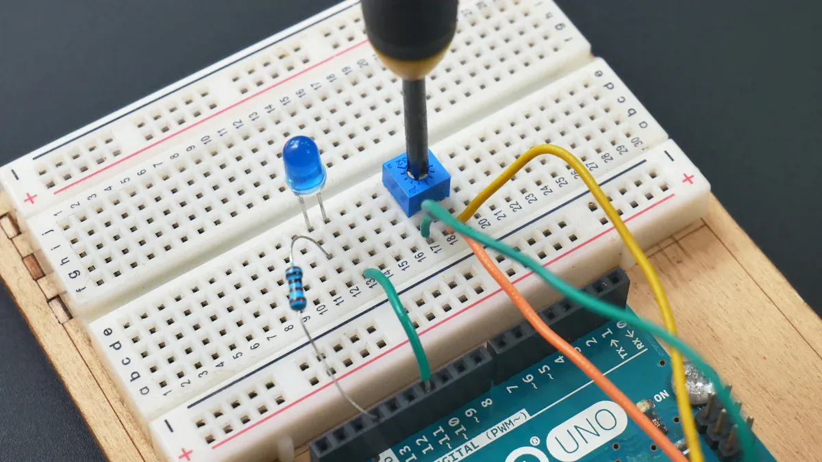
When you work with potentiometers, you will find two main ways to wire them: as a voltage divider or as a variable resistor. Each setup has its own purpose and wiring method. This section will guide you through both, show you practical tips, and help you avoid common mistakes. These potentiometer wiring examples will help you build circuits that work the way you want.
Voltage Divider
You often use a potentiometer as a voltage divider. This setup lets you create an adjustable output voltage from a fixed input voltage. You use all three pins for this configuration.
To wire a potentiometer as a voltage divider:
- Connect one outer pin (Pin 1) to the input voltage (Vin).
- Connect the other outer pin (Pin 3) to ground.
- Take the output voltage from the middle pin (Pin 2), which is the wiper.
When you turn the knob, the wiper moves along the resistive track. The output voltage at the wiper changes smoothly from 0 volts (ground) up to nearly the input voltage. This happens because the potentiometer splits the voltage between the two ends, depending on the wiper's position. Both rotary and slide potentiometers use this standard wiring scheme.
Tip: Always check the potentiometer symbol in your circuit diagram. Pins 1 and 3 are the resistor ends, and pin 2 is the wiper. This helps you match the physical pins to your circuit.
Here is a simple code block to show the wiring:
Vin ----[Pin 1]---+
                  |
                [Potentiometer]
                  |
GND ----[Pin 3]---+
                  |
           [Pin 2]----> Vout (variable)
This method works well for volume controls, sensor adjustments, and many analog circuits.
Variable Resistor
You can also use a potentiometer as a variable resistor, sometimes called a rheostat. In this setup, you only use two pins: the wiper (Pin 2) and one of the outer pins (Pin 1 or Pin 3). The other outer pin stays unconnected or, for better reliability, you can connect it to the wiper.
- Connect the wiper (Pin 2) to one point in your circuit.
- Connect one outer pin (Pin 1 or Pin 3) to the other point.
- Leave the unused pin floating, or tie it to the wiper for safety.
This wiring lets you adjust the resistance between the two connected pins. You use this method when you want to control current or resistance, such as in a 555 timer circuit or to adjust the brightness of an LED.
- Wiring a potentiometer as a variable resistor uses only two terminals: the wiper and one end terminal.
- This avoids open circuits if the wiper loses contact, because the resistance stays at maximum instead of breaking the circuit.
- The direction you turn the knob depends on which end pin you use. Choose the pin that gives you the increase or decrease in resistance you want.
Note: If you want the resistance to always stay in the circuit, connect the wiper to one end pin. This way, if the wiper loses contact, the circuit still has resistance and does not open.
Troubleshooting
Sometimes, your potentiometer wiring does not work as expected. Here are steps and tips to help you find and fix problems:
- Use an ohmmeter or multimeter with the power off. Measure the resistance between each potentiometer terminal and the circuit common point. This helps you find if both ends are accidentally connected together or to ground.
- Set the potentiometer to about halfway before measuring. This gives you meaningful readings.
- Look for unexpected resistance values. If you see low resistance between the maximum end and ground, or if the input and output seem tied to the wiper, you may have a wiring mistake.
- Resolder all potentiometer and related circuit connections. This removes solder bridges and ensures good contact.
- Understand how your circuit should work. Knowing the expected behavior helps you spot mistakes or wrong part values.
Tip: Always consult the datasheet for your potentiometer. The datasheet shows the correct pinout and helps you wire the potentiometer for the direction and function you want.
Common Mistakes to Avoid
- Leaving one pin unconnected can cause noise in your circuit. The unused pin may act like an antenna.
- Not connecting both ends of the potentiometer can lead to open circuits if the wiper connection fails.
- Incorrect orientation can make the resistance change in the opposite direction than you expect. This is important for volume controls and other user-facing adjustments.
- Soldering mistakes can cause poor connections. Always insert the potentiometer pins into the correct holes on the PCB and solder from the back side. Make sure all pins are secure.
Callout: For heavy or panel-mount potentiometers, do not solder them directly to the PCB. Use wires to connect them, and secure them with mounting hardware to avoid damage.
By following these potentiometer wiring examples and tips, you can avoid common pitfalls and build reliable circuits. Careful wiring and testing ensure your potentiometer works as intended.
Choosing a Potentiometer
Selection Tips
You need to choose the right potentiometer for your circuit to get the best results. Start by checking the resistance value. Common values include 1 kΩ, 10 kΩ, and 100 kΩ. Most circuits work well with a 10 kΩ potentiometer. The resistance value affects how the potentiometer divides voltage and controls the resolution of your adjustments.
Next, look at the power rating. The potentiometer must handle the power in your circuit without overheating. Most potentiometers work with less than one watt. If you use too much power, the device can get hot and fail. You can lower power use by controlling the voltage applied to the potentiometer, such as using a microcontroller output pin.
Consider the adjustment method. You can pick rotary or sliding types. Rotary potentiometers use a knob, while sliding types use a lever. Choose the style that fits your project.
Check the mechanical characteristics. Look at the size, mounting style, and shaft type. Make sure the potentiometer fits your circuit board or panel. If you need high accuracy, select a multi-turn or digital potentiometer.
Environmental needs matter too. If your circuit faces moisture, dust, or heat, pick a potentiometer that resists these conditions. Some models offer waterproof or dustproof features.
Here is a table to help you compare important factors:
| Factor | What to Check |
|---|---|
| Resistance Value | Match to your circuit (1 kΩ, 10 kΩ, 100 kΩ, etc.) |
| Power Rating | Must handle the circuit’s power without overheating |
| Adjustment Method | Rotary knob or sliding lever |
| Mechanical Characteristics | Size, mounting style, shaft type |
| Resolution | Fineness of adjustment possible |
| Environmental Needs | Waterproof, dustproof, heat resistance |
Tip: Always check the datasheet for details about resistance, power rating, and mounting style.
Pinout Considerations
Correct pinout selection keeps your potentiometer working as expected. You must connect the pins properly. The center pin is usually the wiper. One outer pin connects to power, and the other goes to ground. If you wire the pins incorrectly, the potentiometer may not change resistance when you turn the knob. Wrong connections can cause short circuits, damage components, or create unreliable signals.
Poor pinout wiring can also lead to overheating. Always confirm the pinout using the datasheet and test with a multimeter before final assembly. If you use a model like the 3296 potentiometer, remember that the two outer pins connect to the ends of the resistive track, and the middle pin is the wiper.
Note: Careful pinout selection prevents circuit problems and keeps your potentiometer reliable.
You now understand how potentiometer pinout shapes circuit design.
- Potentiometers use three terminals to divide voltage, which is vital for correct wiring.
- Knowing wiring configurations and mounting styles helps you fit potentiometers into PCBs and panels.
- Potentiometers control voltage with three terminals, while rheostats use two for current.
- Choosing the right resistance value, taper type, and power rating ensures reliable performance.
- Symbols and markings guide you during identification and wiring.
Try these hands-on steps to deepen your skills:
- Measure resistance between the wiper and each end terminal, watching how it changes.
- Build a simple circuit to control motor speed using two terminals.
- Check voltage across the motor to confirm your wiring.
Explore resources like Analog Devices’ application notes and the Same Sky Devices blog for more details on datasheets and pin identification. You gain confidence by testing and learning with real components.
FAQ
What happens if you wire a potentiometer pinout incorrectly?
If you wire the pins incorrectly, the potentiometer will not control voltage or resistance as you expect. You might get no change, sudden jumps, or even damage your circuit. Always check the datasheet and test with a multimeter before final wiring.
How do you know which pin is the wiper?
You can find the wiper by looking for the middle pin on most potentiometers. If you turn the knob and measure resistance, the wiper pin shows changing resistance to both end pins. The datasheet also marks the wiper as pin 2.
Can you use a potentiometer as a simple on/off switch?
No, a potentiometer cannot act as a true on/off switch. It changes resistance smoothly. If you need on/off control, use a mechanical switch. Potentiometers work best for adjusting levels, not for switching circuits.
Why does the potentiometer value matter in your circuit?
The value sets the range of resistance or voltage you can adjust. If you pick a value too high or too low, your circuit may not work right. Always match the potentiometer value to your circuit’s needs for best results.
Do all potentiometers have the same pinout?
Most standard potentiometers use the same pinout, but some special types may differ. Always check the datasheet for your specific model. Testing with a multimeter helps confirm the correct pin arrangement.