Is Your TVS Diode Working? Here's How to Check
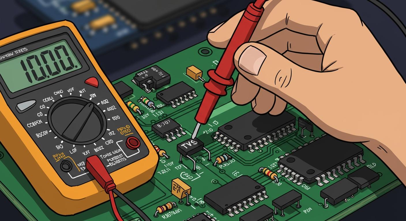
You can check your TVS diode with a few simple methods. These transient voltage suppressors provide essential overvoltage protection against damaging voltage spikes. Shockingly, these electrical spikes cause as many as 75% of all circuit failures. A faulty diode offers no protection against a power surge.
Quick Tip: For fast testing, use your multimeter. A reading near zero ohms on your digital multimeter often means you have a shorted diode. This is the most common way a TVS diode fails. A good diode will read differently on a multimeter.
Key Takeaways
- You can check a TVS diode with a multimeter. This helps find common problems like a short circuit.
- Always test the diode outside of the circuit. This prevents wrong readings from other parts.
- A simple diode test checks basic function. An advanced voltage test confirms the diode's ability to stop power surges.
- Compare your test results with the diode's datasheet. This ensures it works as it should.
TOOLS FOR THE JOB

You need the right tools to diagnose your TVS diode correctly. Luckily, the most common tests require only basic equipment you might already own. More advanced tests need a few specialized items to get a definitive answer.
BASIC MULTIMETER TESTS
You can perform simple checks with just a few items. These tools help you quickly find the most common failure: a shorted diode. Your primary tool will be a standard digital multimeter.
- A Multimeter: This device is essential. You will use its resistance (Ohms) and diode test functions.
- Test Probes: Your multimeter comes with these. Fine-tipped probes are helpful for testing small, surface-mounted components.
- Tweezers (Optional): Non-conductive tweezers help you handle tiny diodes safely without damaging them.
ADVANCED VOLTAGE TEST
Confirming a diode's exact breakdown voltage requires more than a simple multimeter. This test actively stresses the component to verify its performance against its datasheet specifications. You should only attempt this test if you are comfortable working with live circuits.
Required Advanced Equipment ⚙️
- Variable DC Power Supply: You need this to slowly increase the voltage applied to the diode.
- Series Resistor: A current-limiting resistor (e.g., 1kΩ) protects the diode from damage during the test.
- A Second Multimeter: You will use this to accurately measure the voltage directly across the TVS diode as it begins to conduct.
QUICK CHECK: TESTING FOR SHORTS
The most common failure for a TVS diode is a short circuit. When a powerful voltage spike overwhelms the component, it can fail permanently. This creates a direct, low-resistance path to ground. You can easily find this problem with your multimeter's resistance test. A shorted diode offers zero protection.
Why does a diode fail this way? ⚡
- Junction Destruction: Intense heat melts the internal semiconductor materials, causing them to fuse together.
- Metallization Bridge: Metal layers inside the diode can melt and splash, forming a conductive bridge across the component.
- Localized Hot Spots: A very fast energy spike creates a tiny super-heated channel that damages the silicon.
- Thermal Runaway: A feedback loop where rising heat causes more current leakage, which in turn creates even more heat until the diode melts down.
SETTING UP THE OHMS TEST
You will use your multimeter to measure the resistance across the diode. This test quickly tells you if the component has shorted out.
- Disconnect Power. Always make sure the circuit is completely powered off before you test any component.
- Isolate the Diode. For the most accurate reading, you should test the diode out-of-circuit. Other components can affect your multimeter reading. If you cannot remove it, be aware that your results may not be definitive.
- Set Your Multimeter. Turn the dial on your digital multimeter to the resistance setting, marked with the omega symbol (Ω).
- Connect the Probes. Touch the multimeter probes to each lead of the diode. The polarity (which probe goes on which lead) does not matter for this specific resistance test.
INTERPRETING THE RESULTS
The reading on your multimeter screen tells you the state of the diode. A good diode acts like an open switch, while a failed one acts like a closed wire.
Good Diode vs. Shorted Diode
- A Good TVS Diode: Your multimeter should show a very high resistance. It will likely read "OL" (Open Loop), "O.L.", or a "1" on the far left of the display. This means the resistance is too high for the multimeter to measure, which is the correct reading for a healthy diode.
- A Shorted Diode: The multimeter will display a very low resistance, typically a value close to 0 Ω. If your meter has a continuity function on the same setting, it will also likely beep. This reading confirms the diode has failed and needs replacement.
USING THE DIODE TEST FUNCTION
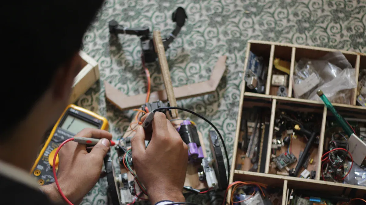
While the resistance test is great for finding a dead short, the diode test function on your multimeter gives you a much better look at the component's health. This test is the best approach for checking a TVS diode. It does more than just check for continuity. It actively measures the forward voltage drop across the semiconductor junction, which is a key characteristic of a working diode.
Your multimeter sends a small, constant current through the diode when in this mode. It then displays the voltage required to turn the diode "on" in the forward direction. This gives you a clear pass or fail result.
TESTING A UNIDIRECTIONAL DIODE
A unidirectional TVS diode behaves like a standard diode in the forward direction. You will test it in both directions to confirm its function.
- Set Your Multimeter. Turn the dial to the diode test setting. This is usually marked with a diode symbol (a triangle with a line).
- Test the Forward Bias. A unidirectional TVS diode has a marking, often a band, indicating the cathode (negative) side. Place the red (positive) probe on the anode (the unmarked side) and the black (negative) probe on the cathode (the marked side). For a good silicon diode, you should see a reading between 0.5V and 0.8V. This is the forward voltage drop.
- Test the Reverse Bias. Now, swap the probes. Place the black probe on the anode and the red probe on the cathode. A healthy TVS diode will block current in this direction. Your multimeter should display "OL" (Open Loop) or a similar indicator, showing that the resistance is too high to measure.
TESTING A BIDIRECTIONAL TVS DIODE
A bidirectional TVS diode is designed to clamp voltage in both directions. It essentially acts like two opposing diodes connected in series. Because of this structure, testing it with a standard diode function is very simple.
You should test it just like a unidirectional diode, but the results will be different.
- Place the probes on the leads of the bidirectional TVS diode.
- Note the reading. It should be "OL".
- Now, reverse the probes.
- You should see "OL" again.
A good bidirectional TVS diode will not conduct in either direction during this low-voltage test. It should appear as an open circuit from both sides.
UNDERSTANDING THE READINGS
The reading on your screen quickly tells you if your diode is good, shorted, or open. A shorted diode is a common failure, but an open diode is also possible, where the component is internally broken and does not conduct at all. An open diode offers no protection.
Here is a simple guide to what your readings mean:
| Diode Type | Test Condition | Expected Reading for a GOOD Diode | Reading for a FAILED Diode |
|---|---|---|---|
| Unidirectional | Forward-Biased | ~0.5V to 0.8V | "OL" (Open) or ~0V (Shorted) |
| Unidirectional | Reverse-Biased | "OL" (Open Loop) | ~0V (Shorted) |
| Bidirectional | Probes in one direction | "OL" (Open Loop) | ~0V (Shorted) |
| Bidirectional | Probes reversed | "OL" (Open Loop) | ~0V (Shorted) |
What do the readings tell you? 💡
- A Reading of ~0V: This indicates a shorted diode. The component has failed and is creating a direct path, offering no protection. You must replace this diode.
- A Reading of "OL" in Both Directions (for a unidirectional diode): This points to an open diode. The internal connection is broken, and it cannot protect the circuit. This diode also needs replacement.
- Correct Readings: If your TVS diode provides the readings listed in the "GOOD Diode" column, it has passed this basic functional test.
ADVANCED TEST FOR OVERVOLTAGE PROTECTION
Multimeter tests are useful, but they cannot confirm a TVS diode's primary function: its ability to clamp voltage spikes. A simple multimeter test might show a diode is not shorted, but it will not reveal if the component is fake or has a faulty breakdown voltage. This advanced test is the only way to be certain your TVS diode provides real overvoltage protection. It measures the exact voltage at which the diode begins to conduct, ensuring it can stop a dangerous electrical surge. This test confirms the diode offers the protection your circuit needs from damaging electrical spikes.
REQUIRED ADVANCED EQUIPMENT
You need specific tools to perform this definitive test. This setup allows you to safely apply and measure the breakdown voltage of the TVS diode.
- Variable DC Power Supply: This lets you slowly increase the voltage.
- Current-Limiting Resistor: A 1kΩ resistor is a good choice. It protects the diode from excessive current during the test.
- Two Multimeters: You will use one to monitor the power supply output and a second to measure the voltage directly across the diode.
MEASURING BREAKDOWN VOLTAGE
This procedure involves applying a live voltage to the diode. You must follow safety protocols to prevent injury and equipment damage. The goal is to find the voltage where the diode "turns on" to block electrical spikes.
Safety First! Working with Live Voltage ⚠️
You are creating a live electrical circuit. Always prioritize safety.
- Wear proper Personal Protective Equipment (PPE), including safety glasses.
- Keep one hand in your pocket when possible. This prevents creating a closed circuit through your body.
- Work in a well-lit area away from any water.
- Double-check your connections before applying power. A mistake could damage the diode or your equipment.
- Build the Circuit. Connect the power supply, the 1kΩ series resistor, and the TVS diode. Ensure you connect the diode in reverse bias for a unidirectional diode.
- Connect the Multimeters. Place one multimeter to measure the voltage across the TVS diode.
- Apply Voltage Slowly. Start with the power supply at 0V. Gradually increase the voltage.
- Watch the Diode Voltage. As you increase the supply voltage, the voltage across the diode will also rise. At a specific point, the voltage across the diode will stop rising. This is the breakdown voltage. The diode is now clamping the voltage and providing protection from further spikes.
COMPARING WITH THE DATASHEET
The final step is to compare your measurement with the component's official specifications. This confirms if the diode is performing correctly.
First, find the datasheet for your specific TVS diode. Look for the "Electrical Characteristics" table. You need the value for Breakdown Voltage (VBR). This is the voltage where the diode is designed to activate its protection.
Your measured breakdown voltage should be very close to this VBR value. Most diodes have a tolerance of around 5%. If your measured voltage falls within this range, your diode is working perfectly and will protect your circuit from a power surge and other voltage spikes. If the reading is far off, the diode is faulty and cannot be trusted to stop harmful spikes.
THE IMPORTANCE OF OUT-OF-CIRCUIT TESTING
You might be tempted to test a TVS diode while it is still soldered to the circuit board. This seems faster, but it often leads to wrong conclusions. Testing a component in-circuit can give you false readings. You should always test the diode out-of-circuit for a reliable diagnosis. Removing the component isolates it from everything else. This ensures your multimeter measures only the diode itself.
AVOIDING FALSE READINGS
When you test a diode on a board, your multimeter can be easily tricked. Other components connected in parallel with the TVS diode create alternate paths for the test current. This can make a good diode appear faulty or a bad diode seem fine.
What is a Parallel Path? ⚡
Imagine a river that splits into two smaller streams and then joins back together. If you measure the water flow in one stream, you are not measuring the total flow of the river. Similarly, your multimeter's current can flow through the diode and other components like resistors or capacitors. This "parallel path" skews your measurement, making it impossible to know the true condition of the diode.
This is why an in-circuit test might show a low resistance reading, suggesting a short. In reality, you could be measuring the resistance of another part of the circuit.
ENSURING ACCURATE DIAGNOSIS
Removing the TVS diode from the circuit is the only way to guarantee an accurate test. This step eliminates any doubt about your findings. You can be confident that your multimeter reading reflects the true state of the component you are testing. An accurate diagnosis is critical for any electronic repair.
Taking the extra minute to desolder the diode provides several key benefits:
- Certainty: You know for sure if the diode is good or bad.
- Precision: Your measurements are not influenced by other components.
- Efficiency: You avoid wasting time and money replacing the wrong parts.
By isolating the component, you confirm whether the diode itself is the problem. This simple action is the most important step for a correct and successful repair.
You now have the knowledge to check your TVS diode. A shorted diode is the most common failure, and your multimeter can find it quickly. This testing ensures your TVS diode provides the protection your circuits need.
Your Testing Toolkit Summary 🛠️
- Ohms Test: Finds a shorted diode.
- Diode Test: Checks basic function.
- Voltage Test: Confirms true protection from a power surge.
You can confidently determine if your TVS diode works. This simple diode is your first defense against a power surge, voltage spikes, and other harmful electrical spikes. Proper protection shields your electronics from damaging electrical spikes.
FAQ
Can I test a TVS diode while it's on the board?
You can try, but the results are not reliable. Other components create parallel paths that can trick your multimeter. For an accurate diagnosis, you should always remove the diode from the circuit before testing it.
What is the main difference between unidirectional and bidirectional diodes?
A unidirectional diode protects against voltage spikes in one direction. A bidirectional diode protects against spikes in both positive and negative directions. You test them differently with a multimeter's diode function.
Why did my multimeter beep when I tested the diode?
A beep during a resistance or continuity test usually means you have a shorted diode. 🔊 The meter found a very low resistance path, which indicates the component has failed and needs replacement.
Does a good diode test guarantee my TVS diode works?
Not completely. A good diode test shows the component is not shorted or open. However, it does not confirm the diode's breakdown voltage. Only an advanced voltage test can verify its ability to stop a power surge.