How Can You Test an Insulated Gate Bipolar Transistor at Home
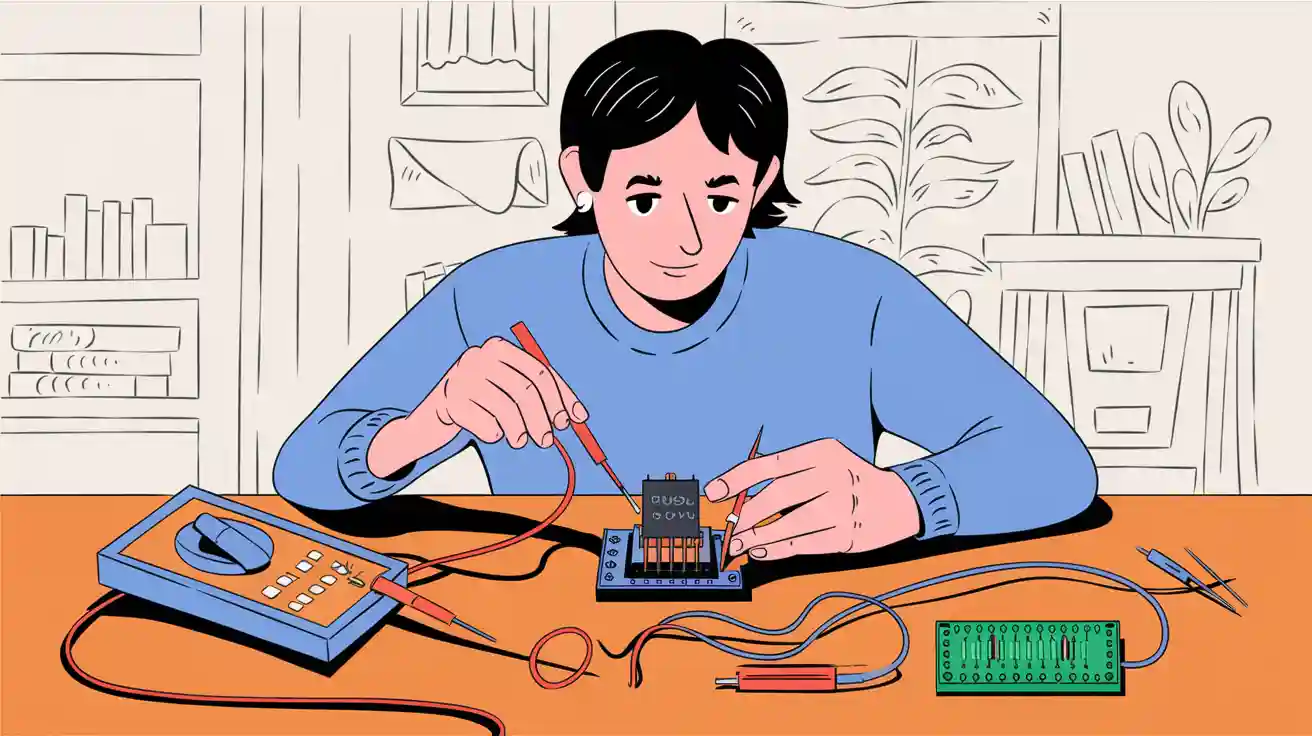
You can test an insulated gate bipolar transistor at home with just a few simple tools. Start by identifying the IGBT terminals. Use a digital multimeter for basic checks. Always keep safety first and follow each step carefully. This practical guide helps you avoid mistakes and get accurate results.
Key Takeaways
- Identify the IGBT terminals: collector, emitter, and gate. Use the datasheet for accurate pin layout.
- Always prioritize safety: turn off devices, wear gloves, and use insulated tools to prevent electric shock.
- Use a digital multimeter for testing: check voltage drops and resistance to assess IGBT health.
- Look for common signs of failure: low resistance or visible damage can indicate a faulty IGBT.
- Practice makes perfect: retest if results are abnormal and learn from mistakes to improve your skills.
Insulated Gate Bipolar Transistor Basics
IGBT Terminals
When you look at an insulated gate bipolar transistor, you will see three main terminals. These are the collector, the emitter, and the gate. Each terminal has a special job:
- The collector receives the main current.
- The emitter lets the current flow out.
- The gate controls when the current flows between the collector and emitter.
You often find IGBTs in devices like switch mode power supplies, electric motor circuits, air conditioners, and refrigerators. Companies such as Motorola, ST Semiconductor, and Mitsubishi make low-power IGBT models for home appliances. You can also spot IGBTs in microwave ovens, washing machines, induction cookers, cameras, and electronic rectifiers.
Tip: Always check the datasheet for your IGBT. The datasheet shows the exact pin layout for your model.
How IGBTs Work
You use an IGBT as a high efficiency electronic switch. It combines the best features of two types of transistors. The internal structure has a P-N-P-N layer, which helps the IGBT switch and amplify current. The gate works like a MOSFET, using an insulating layer to separate the control signal from the main current. This design makes the IGBT very efficient and reliable.
IGBTs handle high-current applications and work well in high-voltage circuits. The bipolar junction inside lets the device amplify current, which is important for devices that need a lot of power. The silicon dioxide layer inside the IGBT stops current from leaking, so your device stays safe.
You will see two main types of IGBTs: punch-through IGBT and non-punch-through IGBT. Each type has its own strengths. Punch-through IGBTs work better at higher frequencies, while non-punch-through IGBTs are more robust in tough conditions.
IGBTs play a big role in modern electronics. You find them in electric vehicle inverters, induction heating systems, variable frequency drives, and power supplies. They help manage high power in traction motor control for electric vehicles and trains. IGBTs also ensure smooth transitions in uninterruptible power supplies and switch-mode power supplies.
Tools and Safety for IGBT Testing
Required Tools
You do not need expensive equipment to test an igbt at home. You can use simple tools that you may already have. Here are the main tools you should gather before you start:
- Digital Multimeter: This tool helps you measure voltage, resistance, and continuity. Most digital multimeters have a diode test mode, which is very useful for checking igbt devices.
- Ohmmeter: Some multimeters include this function. You use it to check the resistance between terminals.
- Curve Tracer (optional): This tool shows the current-voltage curve of the igbt. You do not need it for basic tests, but it can help you see more details if you want to learn more.
Tip: Always check that your multimeter works before you begin. A faulty meter can give you wrong results.
Here is a quick table to help you remember the tools:
| Tool | Purpose |
|---|---|
| Digital Multimeter | Measure voltage, resistance, and diode function |
| Ohmmeter | Check resistance between terminals |
| Curve Tracer | View current-voltage curve (optional) |
Safety Precautions
Safety comes first when you test an igbt. You must always turn off and unplug any device before you start. Lock out the power if possible. This step keeps you safe from electric shock.
- Wear rubber gloves to protect your hands.
- Use insulated tools to avoid accidental contact with live parts.
- Work in a dry area to prevent slips or shocks.
- Never touch the igbt terminals with wet hands.
Note: Even after you turn off the power, some circuits can hold a charge. Wait a few minutes before you touch the igbt.
Handle the igbt gently. Static electricity can damage it. Touch a metal object to discharge static from your body before you handle the device. Always follow these steps to keep yourself and your equipment safe.
Test an IGBT: Step-by-Step
Testing an insulated gate bipolar transistor at home can seem tricky, but you can do it with patience and the right steps. This practical guide will help you check your IGBT safely and accurately.
Identify Terminals
Before you start any test, you need to know which pin is which. Every IGBT has three main terminals: collector, gate, and emitter. Follow these steps to identify them:
- Find the IGBT on your circuit board.
- Look up the datasheet for your specific IGBT model. The datasheet shows the pin layout.
- Use the datasheet to match each pin to the collector, gate, or emitter.
Tip: If you do not have the datasheet, search for the part number printed on the IGBT. Most manufacturers provide datasheets online.
Continuity and Diode Test
You can use a digital multimeter to check the basic health of your IGBT. Here is how you do it:
- Make sure the device is powered off and unplugged.
- Set your multimeter to diode test mode (look for the diode symbol).
- Double-check the collector, gate, and emitter pins.
- Place the multimeter leads on the collector and emitter. You should see a voltage drop between 0.3 and 0.7 volts if the IGBT is healthy.
- Move the leads to the gate and emitter. You should see high resistance or no continuity.
- Switch to continuity mode. If the multimeter beeps when you touch collector and emitter, the IGBT may be faulty.
- IGBTs usually show a forward voltage drop of 2 volts or less when turned on.
- If you get a reading outside this range, the IGBT might be damaged.
Note: Always use a calibrated multimeter. Inconsistent readings can mean the IGBT is faulty or the tool is not working right.
Collector-Emitter Junction Test
The collector-emitter junction is key to IGBT operation. You can check it with your multimeter:
- Set the multimeter to resistance (ohmmeter) mode.
- Place one lead on the collector and the other on the emitter.
- A healthy IGBT should show very high resistance, usually above one megaohm.
- Reverse the leads and test again. The reading should stay high.
If you see low resistance in either direction, the IGBT may have an internal short.
Tip: Always wear insulated gloves and inspect the IGBT for physical damage before testing.
Gate Oxide Test
The gate oxide layer keeps the control signal separate from the main current. You can check its integrity with a multimeter:
- Set the multimeter to the R×1KΩ range.
- Measure resistance between the gate and collector, and then between the gate and emitter.
- You should see high resistance (several thousand ohms) in both cases.
- Switch to R×10KΩ for a more sensitive test.
- Touch the gate briefly and see if the IGBT turns on or off as expected.
If the resistance is low, the gate oxide may be damaged.
Alert: Never apply too much voltage to the gate. This can destroy the oxide layer.
Interpret Results
After you finish the tests, compare your readings to the typical values for a healthy IGBT. Use the table below as a reference:
| Test Method | Expected Value |
|---|---|
| Forward Voltage Drop (VF) | 0.3 ~ 0.7 V |
| Resistance between Collector-Emitter | Above Megaohm level |
| Resistance between Gate-Emitter | High impedance (several thousand ohms) |
If your readings match these values, your insulated gate bipolar transistor is likely in good shape. If not, you may need to replace it.
Common Mistakes to Avoid:
- Forgetting to power off the device before testing.
- Setting the multimeter to the wrong mode.
- Using uncalibrated tools.
- Not checking for consistent readings.
You can now test an igbt at home with confidence. Always follow safety steps and double-check your results. This practical guide helps you avoid common errors and keeps your IGBT testing safe and simple.
IGBT Troubleshooting
Abnormal Readings
When you test an igbt at home, you may see readings that do not match the expected values. These abnormal readings can help you spot problems early. You should pay attention to resistance values, waveform shapes, and voltage measurements. Here is a table that shows what these readings can mean:
| Abnormal Reading Type | Indication of Issue |
|---|---|
| Resistance Values | Short or open circuit signals potential issues |
| Waveform Irregularities | Spikes or distortions indicate malfunctioning gate control |
| High-Voltage Measurements | Readings outside specified range suggest insulation problems or internal damage |
If you notice resistance that is too low or too high, the igbt may have a short or open circuit. Irregular waveforms can point to gate control problems. High-voltage readings outside the normal range may mean the insulation inside the igbt is damaged.
Signs of Failure
You can spot signs of igbt failure by looking for certain patterns during your tests. The most common causes include overcurrent, overvoltage, and overheating. Here is a table that lists the main signs and what they mean:
| Failure Type | Description |
|---|---|
| Prolonged Overcurrent Operation | IGBTs should be shut down before reaching the RBSOA limit to prevent damage. |
| Overvoltage and Static Damage | Spike voltages exceeding the IGBT’s maximum rating can cause breakdown damage during shutdown. |
| Overheating Damage | Junction temperature must remain below 150°C to avoid overheating. |
| Main Circuit Voltage Application | Applying voltage in an open state can inadvertently turn on the IGBT, causing damage. |
| Mechanical Stress Damage | External forces or vibrations can induce stress, leading to internal connection damage. |
You may see continuous exposure to thermal stress. This can cause micro-cracks and bond wire lift-off inside the igbt. Over time, these problems can lead to complete failure. If you use a punch-through igbt, you should watch for overheating, especially during high-frequency operation.
Retesting Tips
If your first test shows a problem, you should retest the igbt to confirm the result. Follow these steps for a reliable retest:
- Disconnect power from the device or circuit.
- Set your multimeter to diode test mode.
- Identify the collector, gate, and emitter pins.
- Measure the voltage drop across the collector-emitter and gate-emitter junctions.
- Check for short circuits using continuity or resistance mode.
You can find more troubleshooting help in resources like Circuit Cellar, EE Times, and ScienceDirect. These sources explain how igbt modules work and offer tips for home users. They also describe how to select and use igbt devices safely.
You can test an IGBT at home by following clear steps and using basic tools. Always put safety first and check your equipment before you start. Practice helps you improve your skills. If you make mistakes, learn from them and try again.
Stay curious and keep learning. Every test makes you better!
Common beginner questions include:
- How do you check a VFD IGBT?
- What tools do you need for IGBT testing?
- What safety steps should you follow when testing IGBTs?
Share your questions or experiences in the comments below!
FAQ
How do you check an IGBT in a VFD (Variable Frequency Drive)?
You can remove the IGBT from the VFD circuit. Use a digital multimeter in diode mode. Test the collector-emitter and gate-emitter pins. Compare your readings to the values in the datasheet.
What tools do you need to test an IGBT at home?
You need a digital multimeter. An ohmmeter helps with resistance checks. A curve tracer is optional for advanced users. Always use insulated tools for safety.
Can you test an IGBT without removing it from the circuit?
You get the most accurate results when you remove the IGBT from the circuit. Testing in-circuit can give false readings because of other connected parts.
What are the most common signs of a bad IGBT?
- Low resistance between collector and emitter
- No voltage drop in diode mode
- Visible burn marks or cracks
If you see these signs, replace the IGBT.