A Practical Approach to Relay Testing
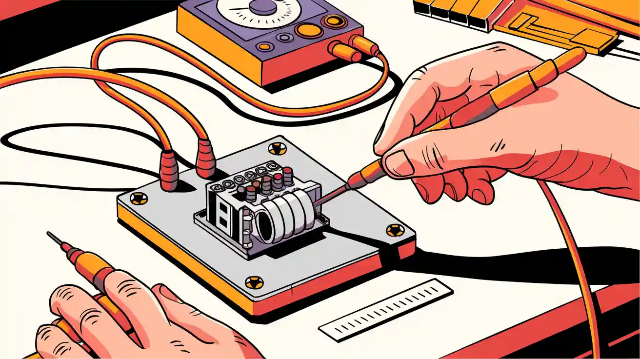
You might wonder how to test a relay when a device stops working. Start by gathering equipment like a multimeter and jumper wires. Use a step-by-step testing procedure: look for damage, find the pin layout, check the coil, power it up, and see if contacts switch. This hands-on guide helps you spot problems quickly. Many relays fail due to excessive current, wear, or harsh environments, as shown below:

You will learn how to test a relay safely and find out what to do if it is faulty.
Key Takeaways
Gather the right tools like a multimeter, jumper wires, and safety gear before testing a relay to work safely and accurately.
Always inspect the relay for visible damage such as burns, cracks, or corrosion before testing to spot problems early.
Identify relay pins using the diagram on the relay or a multimeter to avoid mistakes and ensure correct testing.
Test the relay coil resistance and listen for a click when applying power to check if the relay works properly.
Regularly clean, test, and replace faulty relays to prevent failures and keep your devices running smoothly.
Tools and Safety
Essential Tools
Before you start relay testing, you need to gather equipment that will help you work safely and accurately. The right tools and equipment for testing make the process much easier. Here is a list of what you should have on hand:
Multimeter (digital or analog)
Jumper wires with alligator clips
12V or 24V DC power source (depending on your relay)
Small screwdriver
Needle-nose pliers
A multimeter is the most important tool. You will use it to measure voltage, resistance, and continuity. Make sure you know how to setup multimeter for each test. Jumper wires help you connect the relay to a power source without soldering. The screwdriver and pliers let you handle small parts or remove the relay from its socket. Safety gear protects your hands and eyes from sparks or sharp edges.
Tip: Always check your tools before you begin. Damaged wires or a faulty multimeter can give you wrong results.
Safety Tips
Safety should always come first when working with electrical parts. You must disconnect all power before you touch or remove a relay. This step prevents electric shock and protects your equipment. Never test a relay while it is still in a live circuit.
Wear safety gloves and glasses to protect yourself from accidental sparks or debris. Handle relays gently. Dropping or hitting them can cause hidden damage. If you smell burning or see melted plastic, stop testing right away.
Keep your workspace clean and dry. Water or clutter can lead to accidents. Always follow the instructions for each tool. If you are unsure about any step, ask for help or look up a guide.
Note: Taking a few minutes to check your setup can prevent injury and save your relay from damage.
Visual Inspection
Signs of Damage
Before you test a relay, you should always look for visible signs of damage. Many relay problems show up as physical changes you can spot with your eyes. Experts recommend checking for the following issues:
Burnt or corroded terminals
Cracks on the relay body
Burn marks on the surface
Melted plastic parts
You might also notice overheating, strange or burnt smells, or even see the relay stuck in the 'on' position. Sometimes, a relay will not switch at all. These signs often mean the relay has suffered from too much current or heat. If you see any of these problems, you should clean the relay, check the wiring, and replace the relay if the damage looks severe.
Tip: Always inspect the relay in good light. Use a magnifying glass if you need to see small cracks or burns.
Burnt or Corroded Contacts
Burnt and corroded contacts are some of the most common reasons relays fail in cars and industrial machines. When a relay switches heavy loads, the contacts can spark. This arcing can cause the metal to burn or form a black, carbon layer. Over time, moisture, dust, and corrosive gases make the problem worse. You might see green or white corrosion, or the contacts may look pitted and rough.
Burnt or corroded contacts often cause relays to stop working.
Moisture, dust, and harsh chemicals speed up contact wear.
Voltage spikes can melt contacts, making the relay fail.
Corroded contacts from moisture or chemicals lead to poor connections.
Regular inspection and cleaning help you catch these problems early.
If you find burnt or corroded contacts, you should try to clean them gently. If the damage is too great, replacing the relay is the safest choice. Proper care and regular checks can help your relays last longer and work better.
Identify Relay Pins
Using Diagrams
You need to know which pin does what before you can test a relay. Most relays have a small diagram printed on the case. This diagram shows you the pin numbers and their functions. Follow these steps to identify the pins:
Look for a diagram or chart on the relay casing. This will show you the pin layout and what each pin does.
Find the coil pins first. These are usually labeled with numbers like 2 and 7. The coil pins let you energize the relay.
Next, locate the common (COM) pins. These often use numbers like 1 and 8. The common pins act as the main connection points in the relay circuit.
Identify the normally open (NO) and normally closed (NC) pins. These connect to the common pins when the relay switches.
If you do not see a diagram, use a multimeter. Check for resistance between pins to find the coil. Test for continuity to find the contacts.
Check the relay’s datasheet or manual if you are unsure. Manufacturers sometimes use different layouts.
Always double-check the pin layout before you connect anything. This step helps you avoid mistakes or damage.
Tip: Take a clear photo of the relay diagram before you start. This makes it easier to remember the pin layout later.
Common Pin Layouts
Many relays, especially in cars and machines, use standard pin layouts. You will see these numbers and roles often. Here is a table that shows the most common pin numbers and what they do:
Pin Number | Role in Relay Operation |
|---|---|
Coil pin connected to ground | |
86 | Coil pin connected to switchable power |
30 | Power input pin connected to battery |
87 | Normally Open contact, connects to 30 when coil energized |
87a | Normally Closed contact, connects to 30 when coil not energized |
You may also see relays with a slightly different layout. For example, some relays use 4 pins instead of 5. In those cases, pin 87a is missing. ISO mini relays and micro relays use similar numbers but may swap the positions of pins 86 and 30. Always check the diagram or datasheet for your specific relay.
Note: Knowing the pin layout helps you test and wire the relay correctly. This step is important for safe and reliable operation.
Testing Coil Relays
Measure Coil Resistance
When you start testing coil relays, you need to check the health of the relay coil. You can do this with a multimeter resistance test. First, set your multimeter to the resistance (Ω) setting. Touch the probes to the two coil pins. This step helps you test the coil for breaks or shorts.
If you see a steady resistance reading, the coil is likely in good shape. If the display shows "OL" or zero, the coil may be broken or shorted. Sometimes, the resistance reading changes for a few seconds. This happens because the coil has inductance, which can affect the measurement. Wait for the number to settle before you record the value.
Temperature also affects your results. As the coil heats up, resistance increases. Small changes in resistance are normal. Large jumps or very low readings can mean the coil is damaged. Always measure at room temperature for the most accurate results.
Tip: If the relay does not click when powered, check the coil voltage supply and measure the resistance. This quick check can save you time.
Expected Readings
You should know what numbers to expect when you test the coil. Manufacturer datasheets list typical resistance values for different relay types. For example, a 12 V DC relay coil often measures around 155 ohms. Electromechanical relays usually have coil resistance from hundreds to thousands of ohms. Reed relays show higher resistance, and solid-state relays have much higher values.
Here is a table with common coil resistance values:
Relay Type | Typical Coil Resistance (Ohms) | Typical Coil Current (mA) | Notes |
|---|---|---|---|
Hundreds to thousands | ~40 | Example: 600 Ω coil drawing 40 mA for 8A@250VAC contacts | |
Reed Relay | Around 2400 | ~10 | Similar contact ratings but higher coil resistance and lower current |
Solid-State Relay | Around 24,000 | ~1 | Much higher equivalent coil resistance with very low current, switches higher loads |
Example from datasheet | ~155 | N/A | 12 V DC coil resistance example from manufacturer datasheets |
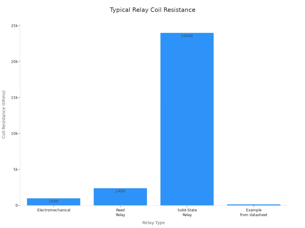
When you test the coil, compare your reading to these values. If your number is far outside the normal range, the relay circuit may not work as expected. Testing coil relays this way helps you spot problems early and keep your devices running smoothly.
How to Test a Relay
Testing a relay is a hands-on process that helps you find out if your relay works as it should. You can follow these steps to make sure you get accurate results. This method works for most automotive and general-purpose relays.
Apply Power to Coil
You need to apply power to the relay coil to see if it activates. Start by making sure you have the right voltage for your relay. Most relays use a 12 VDC coil, but always check the label or datasheet. Using the correct voltage keeps the relay safe and prevents damage.
Here is a table with common voltage values for relay coils:
Voltage Specification | Typical Value (Example) | Description |
|---|---|---|
Nominal Coil Voltage | 12 VDC | The standard voltage at which the relay coil is designed to operate reliably during testing. |
Turn-On Voltage (Max) | 9 VDC | Minimum voltage at which the relay coil must energize and close the contacts. |
Turn-Off Voltage (Min) | 1.2 VDC | Voltage below which the relay coil must de-energize and open the contacts. |
Maximum Coil Voltage | 20.4 VDC | Maximum safe voltage for coil operation, often temperature dependent. |
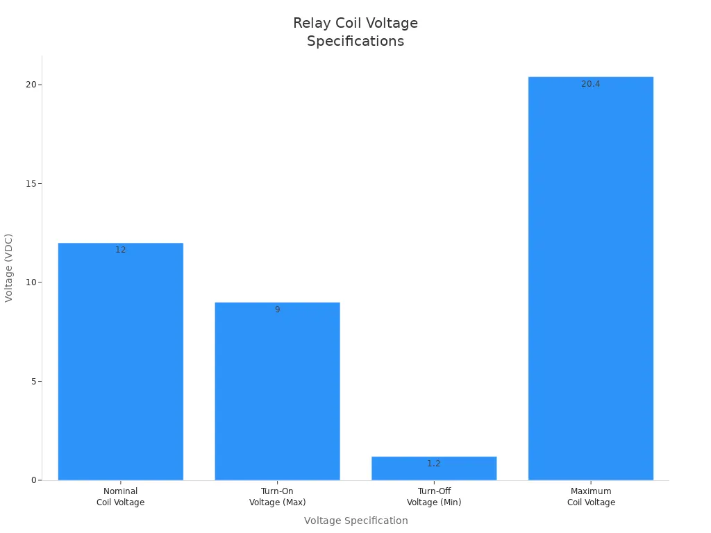
To apply power, connect coil to battery using jumper wires. Attach one wire to pin 85 and the other to pin 86. Make sure you use a battery or power supply that matches the relay’s nominal voltage. If you use less than the turn-on voltage, the relay may not work. If you use more than the maximum, you can damage the coil.
Follow these steps to test a relay:
Gather your tools: battery source, multimeter, alligator clips, and relay diagram.
Set your multimeter to resistance mode (Ω) and measure the coil resistance between pins 85 and 86. A reading between 50 and 200 ohms means the coil is good.
Connect coil to battery by attaching the power source to pins 85 and 86.
Watch for any sparks or overheating. If you see or smell anything unusual, stop right away.
Tip: Always double-check your connections before you apply power. This step helps you avoid short circuits and keeps your relay circuit safe.
Listen for Click
When you energize the relay coil, listen closely for a clicking sound. This click means the relay’s internal switch is moving. The sound tells you that the coil is strong enough to pull the contacts together. If you hear a single, solid click, the relay is working as expected.
The click is a key sign when you want to know how to test a relay. If you do not hear a click, the relay may have a broken coil, stuck contacts, or wiring problems. Sometimes, a weak battery or low voltage can cause the relay to click rapidly or not at all. If you hear a fast, repeated clicking, check your power supply and wiring.
A normal relay click is not a fault. It shows that the relay is switching on and off, just like it should in a working relay circuit. If you do not hear any sound, or if the click is weak or irregular, you may need to replace the relay.
Note: The presence of a click means the relay coil is energized and the contacts are moving. The absence of a click often points to a problem with the relay or the power supply.
Knowing how to test a relay by listening for the click gives you a quick way to check if the relay is alive. This simple test, along with checking the coil resistance and contact continuity, helps you find most relay problems fast.
Test a Relay with a Multimeter
Check Continuity
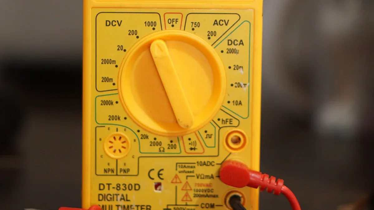
You can use a multimeter to check continuity and find out if your relay works. First, setup multimeter to continuity mode. This mode lets you hear a beep when there is a closed circuit. Follow these steps to test a relay:
Identify the relay coil terminals, usually marked as 85 and 86.
Place the multimeter probes on these terminals and measure resistance. A good relay coil should show between 50 and 120 ohms.
If the reading is infinite or very high, the coil is faulty.
Apply 12V power to the coil (85 to ground, 86 to 12V). Listen for a click. This sound means the relay is switching.
Now, check continuity between the output terminals, usually 30 and 87.
When the relay is not powered, there should be no continuity between these terminals.
When you energize the coil, the contacts close. The multimeter should beep, showing continuity.
If the continuity does not change when you power the coil, the relay contacts may be worn out.
Tip: Always check continuity before and after you apply power. This helps you spot problems with the relay contacts.
Interpret Results
You need to understand what your multimeter readings mean. A working relay shows clear changes in continuity and resistance. Use the table below to compare your results:
Test Aspect | Working Relay Result | Faulty Relay Result |
|---|---|---|
Between 40 and 120 Ohms (normal coil) | Outside 40-120 Ohms (indicates fault) | |
Continuity between COM and NC | Continuity present when relay is de-energized | Continuity absent or inconsistent |
Continuity between COM and NO | Continuity present when relay is energized | Continuity absent or inconsistent |
If you see the right resistance and the continuity changes as you energize the coil, you have a good relay. If the readings do not match, you should replace the relay. Always remember to check continuity at each step to confirm the relay works as expected.
Test an Automotive Relay
Pin Connections
When you test an automotive relay, you need to know the pin layout. Most automotive relays follow the DIN 72552 standard. This system uses specific numbers for each pin. You will see these numbers printed on the relay or in your car’s manual. The most common types are make & break (SPST) with 4 pins and changeover (SPDT) with 5 pins. Here is a table to help you understand the pin functions:
Pin Number | Function |
|---|---|
85 | Relay Coil Negative |
86 | Relay Coil Positive |
30 | Feed / Line In Positive (Common) |
87 | Normally Open Contact (NO) |
87a | Normally Closed Contact (NC) |
You connect pins 85 and 86 to the relay coil. Pin 30 is the main input. Pin 87 is the output when the relay is on. Pin 87a is the output when the relay is off (only on 5-pin relays). Many automotive relays have built-in diodes or resistors between pins 85 and 86. These parts protect your car’s electronics from voltage spikes. General-purpose relays may not have these features. Always check for a diode symbol on the relay case before you connect power.
Tip: If your relay has a built-in diode, match the coil polarity. Connecting it backward can damage the diode.
Swapping Relays
You can use relay swapping as a quick way to test an automotive relay. Mechanics often use this method because it is fast and reliable. Follow these steps:
Find another relay in your car with the same part number. Choose one that controls a non-critical system, like the horn.
Remove both relays from their sockets.
Swap the suspected bad relay with the known good one.
Try to operate the system (for example, start the engine or use the horn).
If the system works with the swapped relay, your original relay is faulty. If it does not work, the problem is somewhere else, such as wiring or a fuse.
Relay swapping works best when relays are easy to reach. Always use a relay with matching specifications. Using the wrong relay can cause damage. If swapping does not solve the issue, you may need more advanced tests or professional help.
Swapping relays is a cost-effective first step. It helps you quickly find out if the relay is the problem.
You now know how to test an automotive relay using pin connections and relay swapping. These methods help you diagnose issues in your car’s electrical system with confidence.
Test a Timer Relay
Timer Function Check
You can test a timer relay by following a clear set of steps. Start by disconnecting the timer relay from the circuit. This prevents interference and keeps you safe. Next, look for any physical damage, such as burnt contacts or cracks. Use a multimeter to measure the coil resistance and compare it with the manufacturer’s specifications.
To check the contacts, measure continuity for the normally open (NO) and normally closed (NC) terminals when the relay is not powered. Apply the rated voltage to the relay coil using a variable power supply. Use a stopwatch or timer to measure the time delay as the relay switches. Repeat this process several times to make sure the relay works the same way each time. You can also connect a load to see if the relay handles the intended current without failing.
Tip: Always compare your measured time delay with the value printed on the relay or in the datasheet. This helps you spot timing errors quickly.
Timer relays control when circuits turn on or off. They use different timing functions to fit many applications. Here is a table showing common timer relay functions and where you might use them:
Timer Relay Function | Description | Typical Applications |
|---|---|---|
On-Delay Timer | Delays closing of contacts after voltage is applied. | Machine start sequences, automation control |
Off-Delay Timer | Contacts remain closed after voltage is removed, then open after delay. | Equipment cool-down, safety shut-offs |
Single-Shot Timer | Provides a single timed pulse independent of input signal duration. | Packaging machinery, alarm triggering |
Flasher Timer | Produces intermittent on/off signals at regular intervals. | Traffic signals, warning lights |
Multi-Function Timer | Combines multiple timing functions (on-delay, off-delay, flasher, etc.) | Complex industrial control, conveyor systems |
Interval Timer | Operates for a set time once energized, then returns to original state. | Washing machines, batch processing |
Common Issues
You may find several problems during time relay testing. Sometimes, the relay does not switch after the set delay. This can happen if the coil is damaged or the contacts are worn out. If you notice the relay switches too early or too late, the internal timer circuit may have failed.
Other issues include inconsistent timing or the relay getting stuck in one position. Moisture, dust, or overheating can cause these problems. If the relay cannot handle the load, it may overheat or fail to switch at all.
Note: If you see any of these issues, replace the relay. Regular testing and inspection help prevent equipment failures and keep your systems running smoothly.
Troubleshooting
No Click Sound
If you do not hear a click when you power the relay, you can follow these steps to find the problem:
Use a digital multimeter to check the coil resistance between terminals 85 and 86. A healthy coil usually reads between 50Ω and 200Ω. If you see a much higher value, the coil may be faulty.
Switch your multimeter to continuity mode. Place the probes on the coil terminals. If you hear a beep, the coil has continuity.
Apply the correct voltage to the coil (terminals 85 and 86). Listen closely for a click. This sound means the relay is switching.
If you still do not hear a click, check continuity between terminals 30 and 87. No beep here can mean the armature is stuck.
Measure the voltage across terminals 30 and 87 when the relay is powered. The voltage should match your power source.
Look for burn marks or mechanical faults on the relay body.
If any test fails, replace the relay with one that matches the original rating.
Tip: Always confirm your power supply voltage before testing. A low or missing voltage can cause the relay to stay silent.
Abnormal Resistance
Abnormal resistance readings often point to coil problems. You might see "OL" (over limit) on your meter if the coil is open. A reading below 5 ohms suggests a shorted coil, often caused by melted insulation. Sometimes, a coil with fewer turns than normal will show lower resistance than expected. These issues can result from voltage spikes, overheating, or using the wrong power supply. Even if an indicator LED lights up, the coil may still be faulty.
Resistance Reading | What It Means | What to Do |
|---|---|---|
OL or infinite | Open coil | Replace the relay |
< 5 ohms | Shorted coil | Replace the relay |
Lower than normal | Fewer coil turns | Replace the relay |
Contacts Not Switching
If your relay clicks but the contacts do not switch, you can try these solutions:
Clean the contacts gently. Use plain printer paper to polish them without removing metal.
Use contact spray for older relays to remove dirt or oxidation.
Unscrew and brush connections with a wire brush to clear corrosion.
Check the coil voltage to make sure the relay is fully energized.
Inspect for bent parts or mechanical blocks inside the relay.
If the relay is very old or damaged, replace it with a modern one.
Improve coil suppression by adding resistors, RC networks, or zener diodes. These methods help reduce arcing and extend contact life.
Regular cleaning and proper coil suppression can help your relay last longer and work more reliably.
If the Relay Is Faulty
Replace the Relay
When you find a faulty relay, you should replace it right away. Using a bad relay can cause bigger problems in your device or vehicle. Always choose a new relay with the same voltage, current rating, and pin layout as the old one. This step keeps your system safe and working as designed.
Relays have different lifespans based on how you use them. For example, automotive relays can last up to 50 million operations if they do not carry a heavy load. Under full load, their electrical life drops to about 50,000 to 500,000 operations. Industrial relays often last longer, sometimes up to 20 million cycles. The table below shows typical relay lifespans:
Relay Type/Condition | Lifespan Range (Operations) | Notes |
|---|---|---|
Mechanical relays (full load) | 50,000 to 100,000 | Typical electrical life at full rated load |
Mechanical relays (light load) | Up to many millions | Mechanical life with negligible load |
Industrial relays | 1,000,000 to 20,000,000 | Depends on type and quality |
Automotive grade relays | 50,000 to 500,000 (electrical life) | Designed for harsh conditions; vibration and shock resistant |
Automotive grade relays | Up to 50 million (mechanical life) | No-load mechanical lifespan |
HVAC product relays | Decades in field use | Confirmed by field studies and user experience |
Tip: Always keep a spare relay on hand for quick replacement. This helps you avoid long downtimes.
Prevent Future Problems
You can make your relays last longer by following a few simple steps. Regular care and testing help you catch problems early and keep your equipment running smoothly.
Exercise relays often to keep springs and moving parts working well.
Clean contacts and relay surfaces with a dry, lint-free cloth or soft brush. Use a no-residue contact cleaner if needed.
Lubricate moving parts only if the manufacturer recommends it. Use greaseless spray lubricants.
Test relays under real-world conditions to check if they trip and reset as expected.
Use test switches to check lockout relays without affecting other devices.
Inspect alarms, meters, and indicators during tests to make sure they work.
Perform timing tests to spot slow or faulty relay actions.
Check breaker trip coils at lower voltages to ensure they work even when power drops.
Keep good records of all tests and maintenance.
Regular inspections and cleaning help you spot damage, dirt, or worn parts before they cause failures. Always follow safety rules and the manufacturer’s instructions for the best results.
By replacing faulty relays quickly and following these maintenance tips, you can prevent most relay problems and keep your systems reliable.
You can test a relay by following clear steps: gather your tools, inspect for damage, identify pins, check the coil, apply power, and measure continuity. Each step helps you find faults quickly and keeps your equipment safe.
Improved testing methods boost diagnostic accuracy up to 97.5% and adapt well to complex conditions.
Regular relay testing increases reliability and prevents costly failures.
Users report higher confidence and fewer mistakes after using these practical steps.
Benefit | Time Savings | Cost Savings |
|---|---|---|
Automated testing | Lower labor costs | |
Quick report creation | Immediate results | Less maintenance |
Try these steps in your next project and share your experience with others!
FAQ
How do you know if a relay is bad?
You can check for a bad relay by listening for a click when you apply power. If you do not hear a click or see no change in continuity, the relay may be faulty.
Can you test a relay without a multimeter?
Yes, you can swap the relay with a known good one from the same system. If the device works after swapping, your original relay is likely bad.
Why does a relay make a buzzing sound?
A buzzing sound often means the relay coil is not getting enough voltage. Loose connections or a weak power supply can also cause this problem.
What happens if you use the wrong relay?
Using the wrong relay can damage your device or cause it to work incorrectly. Always match the voltage, current rating, and pin layout to the original relay.
How often should you test relays?
You should test relays during regular maintenance or if you notice problems with your equipment. Early testing helps prevent bigger failures.