Testing a Diode with a Multimeter Made Easy
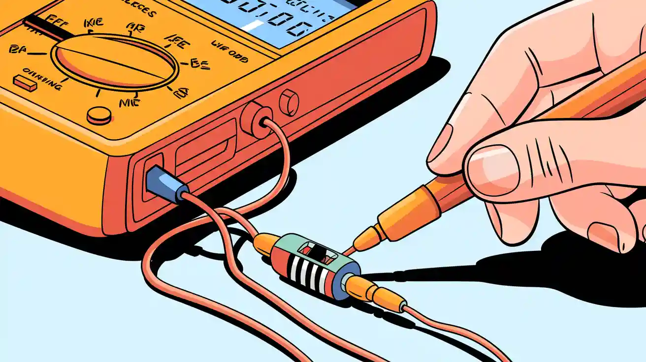
You just need a digital multimeter to check if your diode works. Here’s how to test a diode: set your meter to diode mode, touch the probes to each end, and read the result. No experience needed. You’ll see if the diode passes current or blocks it, all in seconds.
Key Takeaways
- Use a digital multimeter in diode mode to quickly check if a diode is working. This simple test shows if the diode allows current to flow or blocks it.
- Identify the anode and cathode of the diode before testing. The anode is usually the longer lead, and the cathode often has a stripe or marking.
- Perform both forward and reverse bias tests. A healthy diode shows a voltage drop in forward bias and OL (over-limit) in reverse bias.
Identify Diode Terminals
Anode vs. Cathode
Before you test a diode, you need to know which end is which. Every diode has two terminals: the anode and the cathode. The anode is the positive side, and the cathode is the negative side. If you connect them the wrong way, your circuit might not work.
You can spot the difference by looking at the physical features. Here’s a quick table to help you:
| Indicator Type | Description |
|---|---|
| Lead Length | The anode lead is usually longer than the cathode lead. |
| Markings on Casing | The cathode often has a vertical line or bar on the casing. |
| Diode Symbol | The arrow points from the anode to the cathode. |
Sometimes, you’ll see the diode symbol printed on the board. The arrow shows current flow, pointing from the anode to the cathode. If you’re working with a circuit board, look for a bar marking. That bar marks the cathode’s spot.
Finding the Cathode Mark
Finding the cathode is easy if you know what to look for. Most diodes have a stripe or bar near one end. That’s your cathode. If you don’t see a stripe, check the PCB for a bar or symbol. Some boards use a silkscreen design to show polarity.
Here are some tips to confirm the orientation before testing:
- Look for the cathode stripe on the diode body.
- Check for a bar marking on the PCB.
- Use a multimeter in diode mode. Touch the positive probe to one end and the negative to the other. If you see a small voltage drop, you’ve found the anode and cathode.
Beginners sometimes mix up the terminals. You might ignore the bar or assume the longer lead is always the anode. If the markings aren’t clear, grab the datasheet for your diode. Don’t rely only on looks—sometimes, they can fool you!
Tip: If you’re ever unsure, your multimeter can always give you a clear answer. Physical markings help, but a quick test removes all doubt.
How to Test a Diode
Ready to learn how to test a diode? You only need a digital multimeter and a few minutes. Let’s walk through each step together so you can feel confident every time you check a diode.
Set Multimeter to Diode Mode
First, you need to set your multimeter to the right setting. Most digital meters have a special diode test mode. Look for a symbol that looks like a triangle pointing at a line. That’s the one you want.
Here’s how to get started:
- Turn your multimeter’s dial to diode test mode.
- Make sure your probes are plugged in correctly—red in the VΩmA port, black in the COM port.
- Hold the diode so you can see the anode and cathode.
- Get ready to place the probes on the diode’s leads.
Tip: Always use clean probes and check your multimeter’s battery. A weak battery can give you strange readings.
Forward Bias Test
Now, let’s do the forward bias test. This is the main step in how to test a diode. You want to see if the diode lets current flow in the right direction.
Place your probes like this:
| Probe Color | Connection Point |
|---|---|
| Red | Anode |
| Black | Cathode |
When you connect the red probe to the anode and the black probe to the cathode, you are forward-biasing the diode. Your multimeter, in diode test mode, will show a voltage drop if the diode works.
- For a silicon diode, you should see a reading between 0.6V and 0.7V. Sometimes, it might be as low as 0.5V or as high as 0.8V, but most good silicon diodes fall in that range.
- For a germanium diode, the voltage drop is lower—usually around 0.3V.
Here’s a quick table to help you remember:
| Characteristic | Germanium Diode | Silicon Diode |
|---|---|---|
| Forward Voltage Drop | ~0.3V | ~0.7V |
If you see a voltage drop in these ranges, your diode is healthy. If you get a reading of 0V or OL (over-limit), the diode might be faulty.
Note: If you’re using a multimeter and see a voltage drop outside these ranges, double-check your probe placement and try again.
Reverse Bias Test
The last step in how to test a diode is the reverse bias test. This checks if the diode blocks current in the wrong direction.
Switch the probes:
- Place the red probe on the cathode.
- Place the black probe on the anode.
Now, look at your multimeter’s display. In diode test mode, a good diode should show OL (over-limit) or no reading at all. This means the diode blocks current as it should.
If you see a voltage drop or a low reading in both directions, the diode is bad. Sometimes, a faulty diode will show OL in both directions, which means it is open and not working at all.
- A good diode: Voltage drop in forward bias, OL in reverse bias.
- A bad diode: Same reading both ways, or no voltage drop at all.
Keep your multimeter accurate by calibrating it regularly and handling it with care. This helps you get the right results every time you test a diode.
If you follow these steps, you’ll master how to test a diode using a multimeter. Practice a few times, and soon you’ll spot good and bad diodes with just a quick check.
Test a Diode in Circuit
In-Circuit Testing Tips
You might want to check a diode without removing it from the circuit. This can save you time, but you need to watch out for tricky readings. Other parts in the circuit can mess with your results.
The presence of surrounding circuit components can affect the accuracy of in-circuit diode testing with a multimeter by influencing the readings obtained. When testing a diode in-circuit, the readings may be lower than expected due to the influence of other components. If the diode is connected across coils, for example, the resistance of the coil can lead to significantly lower readings compared to testing the diode out of circuit.
Try these tips to get better results:
- Always set your multimeter to diode mode.
- Test both directions, just like you would out of circuit.
- If you see a strange reading, flip the probes and check again.
- Compare your results to what you expect for a good diode.
Sometimes, you might get a reading that looks fine, but the diode is actually bad. Other times, you might see a bad reading, but the diode is good. This happens because other parts in the circuit can change what your meter shows. In-circuit tests can produce false positives or negatives when diagnosing diode faults due to interference from other components in the circuit. For the most accurate results, it is advised to test the diode out of the circuit, as other components connected in parallel can affect the readings.
When to Remove the Diode
If you keep getting odd results, you may need to take the diode out of the circuit. This gives you a clear answer about its health. Here’s what you can do:
- Identify parallel paths in the circuit that may affect the diode's readings.
- Use guarding techniques to isolate unwanted parallel paths by applying a ground at specific nodes.
- Disconnect one end of the diode or temporarily remove nearby components to isolate it.
- If physical disconnection is not feasible, utilize advanced tools like curve tracers for more accurate results.
Generally, diagnosing a faulty component in-circuit is challenging, as it often requires measuring the component outside of the circuit to confirm its condition accurately. While in-circuit tests can be performed in urgent situations, such as diagnosing a BMS fault, they are not as reliable as out-of-circuit tests, which provide clearer results by isolating the component being tested.
Tip: If you want a sure answer, remove one leg of the diode from the board and test it again. This simple step can save you a lot of guesswork.
Understand the Results
Good Diode Readings
When you test a diode, you want to see numbers that match what a healthy part should show. In forward bias, a good silicon diode usually shows a voltage drop between 0.6 and 0.7 volts. Germanium diodes have a lower drop, around 0.3 volts. If you use the resistance mode, a healthy silicon diode should show a value between 1K and 10M ohms in forward bias. In reverse bias, your meter should read OL or infinity, which means the diode blocks current.
Here’s a quick table to help you remember the normal voltage drops for different types:
| Diode Type | Voltage Drop (V) |
|---|---|
| Silicon diodes | 0.6 - 0.7 |
| Germanium diodes | 0.3 - 0.4 |
| Tunnel diodes | 0.2 - 0.3 |
| Schottky diodes | 0.2 - 0.3 |
| Zener diodes | 0.6 - 0.7 |
| Selenium rectifier | 0.9 - 1.2 |
| Power diodes | 0.7 - 0.8 |
| High-voltage diodes | 0.7 - 0.8 |
| LEDs | 1.6 - 1.8 |
Tip: Temperature can change your readings a little. If your room is very hot or cold, the voltage drop might shift slightly.
Faulty Diode Signs
If your diode shows the same reading in both directions, something is wrong. A shorted diode will show a low resistance or voltage drop no matter how you connect the probes. An open diode will show OL or 1 in both directions, which means it does not conduct at all.
Here’s a table to spot problems fast:
| Condition | Expected Reading |
|---|---|
| Healthy Silicon Diode | 0.6 to 0.7 V (forward), OL (reverse) |
| Faulty Diode (Shorted) | Low resistance both ways |
| Faulty Diode (Open) | OL or 1 both ways |
If you get a strange result, try these steps:
- Check if you placed the probes on the right ends.
- Test the diode out of the circuit if possible.
- Try another meter or fresh battery.
- Look for damage or overheating on the diode.
Note: Always double-check your results. Sometimes, other parts in the circuit or a weak battery can trick your meter.
Troubleshooting
Common Issues
When you test a diode with your multimeter, you might run into a few problems. Here are some of the most common issues you could face:
- Testing a diode while it’s still in the circuit can give you strange readings. Other parts connected to the diode can change what your meter shows.
- If you use the resistance mode instead of the diode test mode, you might see the resistance of other components, not just the diode.
- Circuits with low resistance can let current flow and cause false readings.
- If your multimeter is not set to diode mode, it may not apply enough voltage to check the diode properly. You might miss the correct voltage drop and think the diode is bad when it’s not.
- Readings above 0.8 volts in both directions often mean the diode is open and not working. If you see less than 0.6 volts, check the rest of the circuit or take the diode out to test it alone.
Tip: Always double-check your multimeter settings before you start. Using the diode test function gives you the clearest results.
Testing High Voltage Diodes
High voltage diodes need special care when you test them. Many digital multimeters use a low test voltage, sometimes less than 0.3 volts. This low voltage might not be enough to test a high voltage diode, especially if it’s made from several smaller diodes in series. Your meter may not show the usual voltage drop, so you could get confused.
| Consideration | Description |
|---|---|
| Test Voltage | Some meters use low voltage, which may not fully test the diode. |
| Function Usage | Always use the diode check function, not resistance mode, for semiconductors. |
| Reverse Voltage | Never exceed the diode’s rated voltage, or you could damage it. |
- Never try to test high voltage diodes in live circuits. Always make sure the power is off.
- Exceeding your meter’s voltage rating can damage it and put you at risk.
- If you’re not sure, ask a professional for help.
Safety first! Never work on high voltage circuits unless you know exactly what you’re doing.
Testing a diode with your multimeter is quick and reliable. When you understand what the readings mean, you spot problems fast and fix them with confidence. This skill helps you make smart choices in your projects. You can boost your troubleshooting success and keep your electronics running strong. 🚀
FAQ
Can I test a diode without removing it from the circuit?
You can try, but other parts may affect your reading. For the most accurate result, remove one leg of the diode first.
What does “OL” mean on my multimeter?
“OL” stands for “over limit.” Your meter shows this when the diode blocks current. This means the diode is working in reverse bias.
Why does my diode show a voltage drop both ways?
Your diode may be shorted. Replace it if you see a voltage drop in both directions. Always double-check your probe placement before deciding.