Quickly Test Any BJT Transistor With a Multimeter
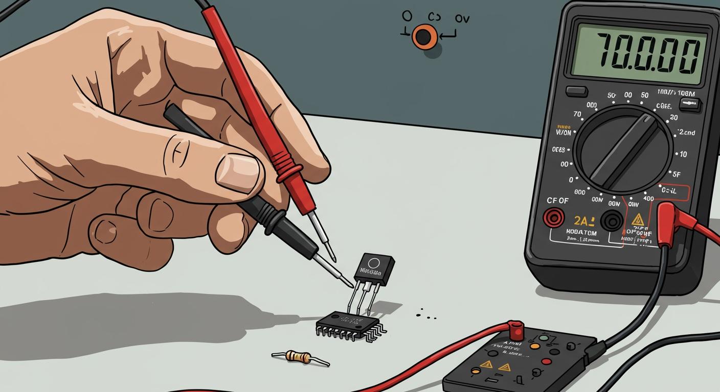
Got a transistor you are not sure about? You can quickly check a transistor in just a few minutes. Your digital multimeter is the only tool you need. A BJT transistor is a three-layer semiconductor device. This special transistor has two internal PN junctions. You can think of a BJT as a unique transistor built from two diodes fused back-to-back.
Your digital multimeter has a Diode Test mode. This function sends a small voltage to test these junctions. This makes using multimeter tests perfect for finding a good transistor or a bad transistor.
Key Takeaways
- Use your multimeter's Diode Test mode to check a BJT transistor. This mode sends a small voltage to test the transistor's internal parts.
- Always remove the transistor from its circuit board before testing. Other parts on the board can make your test results wrong.
- Find the base pin first. This also tells you if the transistor is NPN or PNP. The base pin connects to the other two pins.
- A good transistor shows a voltage reading (around 0.45V to 0.9V) in one direction and 'OL' (open circuit) in the other direction. 'OL' means no connection.
- If your transistor shows 0.0V (shorted) or 'OL' when it should show a voltage (open), it is broken and needs to be replaced.
Preparation for Testing a Transistor

A successful test starts with the right setup. Before you can check a transistor, you need to prepare your tool and the component itself. This preparation ensures your readings are accurate and reliable.
Set the Diode Test Mode
First, you need to configure your digital multimeter. Turn the rotary dial to the Diode Test mode. You can identify this setting by its symbol, which looks like an arrow pointing at a vertical line: →|.
How does it work? In this mode, your digital multimeter sends a small, constant current through its probes. It then measures the voltage drop across the component. This function is perfect for testing the internal PN junctions of a transistor.
Isolate the Component
For an accurate result, you must test the transistor outside of its circuit. Testing a transistor while it is still soldered to a board can give you false readings. Other components on the board can interfere with the measurement from your multimeter.
To isolate the transistor, you will need to desolder it.
- Safety First: Always disconnect the circuit board from any power source before you begin.
- Desolder with Care: A vacuum desoldering station is the best tool for removing a through-hole transistor without causing damage. Using plenty of flux makes the process much easier and protects the component.
If you do not have a vacuum station, a solder sucker or wick can work, but you must be careful not to overheat the board or the transistor.
Identify the Transistor Pins
A BJT transistor has three pins: the Base (B), Collector (C), and Emitter (E). You must know which pin is which to properly test a transistor. Unfortunately, the pinout is not the same for every transistor.
- American TO-92 transistors often use an Emitter-Base-Collector (E-B-C) layout.
- Japanese TO-92 transistors typically use an Emitter-Collector-Base (E-C-B) layout.
The most reliable way to identify the pins is to look up the transistor's datasheet. You can find the datasheet by searching for the part number printed on the transistor. Websites like alltransistors.com or mobile apps like 'Electronic Component Pinouts' are excellent resources for this information.
How to Test a Transistor
You are now ready for the main event: testing a transistor. This process is straightforward once you understand the logic. You will first find the base pin. This discovery also tells you if the transistor is an NPN or PNP type. Then, you will perform a full check on the component.
Find the Base Pin
If you do not have the datasheet, you can find the base pin with your digital multimeter. This method is sometimes called the "one-to-two" method. The base is the one pin that shows a connection to the other two pins.
Here is how you can find the base and identify the transistor type:
- Pick one pin on the transistor to start. Place the red probe of your digital multimeter on it.
- Touch the black probe to each of the other two pins, one at a time.
- Look at the screen. Do you see a voltage reading (like 0.7V) for both connections? If yes, you found the base! The pin under your red probe is the base, and you have an NPN transistor.
- If you do not get two readings, move the red probe to the next pin and repeat the process.
- If you still have not found the base, switch your probes. Place the black probe on a pin and touch the red probe to the other two. If you now get two voltage readings, the pin under your black probe is the base. This means you have a PNP transistor.
Key Takeaway: The base is the only pin that will show a forward voltage drop to both other pins. The polarity of your probes on the base pin tells you if the transistor is NPN or PNP.
NPN vs. PNP BJT Transistor
Bipolar Junction Transistors (BJT) come in two main flavors: NPN and PNP. The names describe the layers of semiconductor material used to build them. An NPN transistor has a P-type layer sandwiched between two N-type layers. A PNP transistor has an N-type layer between two P-type layers.
| Feature | NPN Transistor | PNP Transistor |
|---|---|---|
| Layer Structure | Negative-Positive-Negative | Positive-Negative-Positive |
| Base Probe | Red probe on Base gives readings | Black probe on Base gives readings |
This structural difference is why you use opposite probe polarities to test them. Your multimeter's diode test helps you see this difference clearly. This is the core of bjt testing.
NPN Test Procedure
You found the base with the red probe, so you have an NPN transistor. Now you can perform a full test. This involves checking the two internal junctions in both forward and reverse bias.
1. Forward Bias Tests (Expect a Reading)
- Base-Emitter (B-E) Junction: Place the red (+) probe on the Base and the black (-) probe on the Emitter. You should see a voltage drop between 0.45V and 0.9V.
- Base-Collector (B-C) Junction: Keep the red (+) probe on the Base and move the black (-) probe to the Collector. You should again see a voltage drop, typically slightly lower than the B-E reading.
2. Reverse Bias Tests (Expect 'OL')
- Emitter-Base (E-B) Junction: Place the black (-) probe on the Base and the red (+) probe on the Emitter. Your meter should read 'OL' (Over Limit), indicating an open circuit.
- Collector-Base (C-B) Junction: Keep the black (-) probe on the Base and move the red (+) probe to the Collector. Your meter should again read 'OL'.
3. Collector-Emitter Test (Always 'OL')
- Finally, check the path between the Collector and Emitter. Place your probes on the Collector and Emitter pins. Your meter should read 'OL'. Reverse the probes. You should still see 'OL'. There should never be a direct connection between these two pins on a good bjt transistor.
PNP Test Procedure
You found the base with the black probe, so you have a PNP transistor. The testing procedure is the reverse of the NPN. You will check a transistor of the PNP type using multimeter probes in the opposite configuration.
1. Forward Bias Tests (Expect a Reading)
- Base-Emitter (B-E) Junction: Place the black (-) probe on the Base and the red (+) probe on the Emitter. You should see a voltage drop between 0.45V and 0.9V.
- Base-Collector (B-C) Junction: Keep the black (-) probe on the Base and move the red (+) probe to the Collector. You should see a similar voltage drop.
2. Reverse Bias Tests (Expect 'OL')
- Emitter-Base (E-B) Junction: Place the red (+) probe on the Base and the black (-) probe on the Emitter. Your meter should read 'OL'.
- Collector-Base (C-B) Junction: Keep the red (+) probe on the Base and move the black (-) probe to the Collector. Your meter should again read 'OL'.
3. Collector-Emitter Test (Always 'OL')
- Just like with an NPN bjt, you must test the Collector-to-Emitter path. You can measure a square emitter bjt or any other package type this way. Place your probes on the Collector and Emitter pins. The reading must be 'OL'. Reverse the probes. The reading must still be 'OL'.
Following these steps allows you to test a transistor and determine its health and type with confidence.
Interpreting the Test Results
You have completed the measurements. Now, you need to understand what the numbers on your multimeter screen mean. Interpreting the results is simple if you remember the two-diode analogy. A good bjt transistor behaves like two diodes connected at the base. Your readings will either confirm this model or reveal a fault.
Good Transistor Readings
When you test a transistor and find a forward-biased junction, you are looking for a specific reading. A healthy silicon transistor will show a forward voltage drop.
- You should see a value between 0.45V and 0.9V.
- For most silicon BJT devices, this reading is commonly around 0.7V.
This number represents the small voltage required to push current through the internal PN junction, just like a standard diode. You will get one such reading for the Base-Emitter junction and a similar one for the Base-Collector junction. These two successful readings are the first sign of a good transistor.
Signs of a Faulty Transistor
Bad readings are just as easy to spot. Any result that does not match the expected forward voltage drop or an open circuit in reverse bias points to a faulty transistor. The two main failure types are a short or an open junction.
- Open Junction: If your meter reads 'OL' (Over Limit) when you expect a voltage reading (e.g., in a forward bias test), the junction is broken. No current can flow through it.
- Shorted Junction: If the meter shows a voltage very close to zero, the junction is shorted. This means current passes through with no resistance.
A multimeter reading of 0.02V or a value very near zero indicates a shorted junction in a transistor.
Collector to Emitter Test
This final check is critical. You must test the path between the Collector and Emitter pins. A healthy transistor acts like an open switch between these two pins when it is not turned on. Therefore, you should always see 'OL' on your meter when you check a transistor between the Collector and Emitter, regardless of probe polarity.
If you see any reading other than 'OL'—especially a low value or 0.0V—it means the transistor is shorted between its collector and emitter. This is a common failure mode and a clear sign that you need to replace the transistor. To successfully test a transistor, this check is non-negotiable.
You now know a good bjt transistor behaves like two simple diodes. This makes testing any transistor a quick job. A healthy transistor will pass the test, while a faulty transistor will fail.
A good transistor shows a forward voltage reading and an open 'OL' reading for both internal junctions. A shorted transistor (0.0V) or an open transistor ('OL' when a reading is expected) is a bad transistor.
You can now confidently test any bjt. This skill helps you find a broken transistor in your electronics projects. You can spot a good transistor or a bad transistor with ease.
FAQ
Can I test a transistor while it is on the board?
You should always remove the transistor first. Other components on the board can give you false readings. A reliable test requires you to check the transistor as an isolated component.
Why is my transistor reading not 0.7V?
Most silicon transistor devices show a reading between 0.45V and 0.9V. A germanium transistor will have a lower reading, often around 0.3V.
Tip: Always check the datasheet for your specific transistor. It lists the correct forward voltage drop you should expect.
Does this test work for every transistor?
This guide is specifically for a BJT transistor. The method will not work for other types, like a MOSFET. You must use a different procedure to test that kind of transistor. This test only confirms a BJT transistor.
What does 'OL' mean on my multimeter?
'OL' stands for Over Limit or Open Loop. It means your multimeter cannot detect a connection between the probes. This is the correct reading for a reverse-biased junction on a good transistor.