Mastering LDO Regulator Selection Beyond the Datasheet
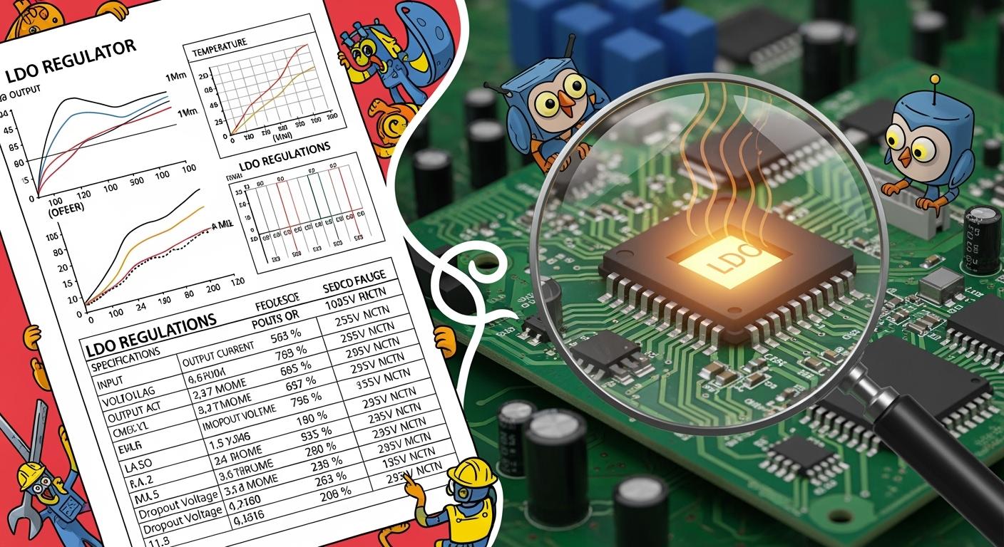
You matched the input and output voltages, but your sensitive circuit is still noisy. What did you miss? This guide moves you beyond basic matching for your ldo. The demand for a better low drop-out ldo is rising in sensitive applications. True engineering means analyzing how this linear voltage regulator performs in the real world. A great ldo regulator provides a clean output from a noisy input, a critical task for any modern regulator.
Key Takeaways
Look beyond basic voltage and current numbers when choosing an LDO. Check how much power it uses when idle, called quiescent current (Iq), to save battery life.
Examine graphs in the datasheet. These graphs show how the LDO performs with different loads, voltages, and temperatures. This helps you predict real-world power use.
Check the LDO's ability to block noise (PSRR) and its own internal noise. This is important for sensitive circuits to get a clean, stable power supply.
Understand how much heat the LDO makes. Calculate power dissipation and use thermal resistance to make sure the LDO stays cool and works reliably.
Efficiency Beyond Dropout Voltage
You often look at dropout voltage first when thinking about efficiency. A low drop-out value is important, but it does not tell the whole story. True efficiency, especially for battery-powered devices, depends on currents you might overlook. Quiescent current (Iq) and ground current (Ignd) are the real power thieves in always-on or idle systems. They determine how long your battery actually lasts.
Quiescent Current (Iq) vs. Shutdown Current
You need to understand the difference between quiescent current and shutdown current. They are not the same. Quiescent current (Iq) is the very small current the ldo uses to power its own internal circuitry while it is active and regulating the output voltage. Shutdown current is the even smaller current drawn when you disable the ldo, usually with an enable (EN) or chip enable (CE) pin.
💡 Pro Tip: Think of it this way: Quiescent current is the power your car's engine computer uses while idling at a stoplight. Shutdown current is the tiny amount of power the car's electronics use when the car is completely turned off.
The following table clarifies the key differences:
Feature | Quiescent Current (Iq) | Shutdown Current |
|---|---|---|
Operational State | The LDO is ON and regulating. | The LDO is OFF via its enable pin. |
Output Voltage | A stable output voltage is present. | The output voltage drops to 0V. |
Purpose | Powers the LDO's internal control circuit. | Minimal current draw in a disabled state. |
Alternative Term | Current Consumption | Standby Current |
For IoT devices that spend most of their time in a standby or sleep mode, a low quiescent current is absolutely critical. It is often called a "silent killer" of battery life. In these standby states, the Iq of the power supply is the largest source of power consumption. Reducing the current draw by just one microamp in a system with a 40-mAh battery could extend its shelf life by about three months. This shows the huge impact of a low Iq.
Understanding Ground Current (Ignd)
Ground current (Ignd) is the current that flows from the ldo's ground pin. In many datasheets, you will see the terms quiescent current and ground current used interchangeably. Both refer to the current the linear voltage regulator consumes to operate, separate from the current it delivers to your load. This ground current and the load current both contribute to the ldo regulator's total power dissipation.
The efficiency of an ldo is calculated with this formula:
Efficiency = (VOUT * IOUT) / (VIN * (IOUT + Ignd))
This equation shows that to get the highest efficiency, you must keep the ground current as low as possible. This is especially true at light loads. For example, imagine a 2.3V battery powers a 1.8V circuit drawing 2µA through an ldo with a 1µA quiescent current. At this very light load, the ldo's own consumption can account for nearly 70% of the total power loss.
Analyzing Power Consumption Graphs
A single "typical" Iq value in a datasheet summary is just a starting point. You must look deeper. Datasheets provide graphs that show how these currents behave under different conditions.
Look for a graph of Ground Current vs. Load Current. This chart reveals how much power the regulator wastes as your device's needs change. An ideal ldo would have a flat, low Ignd across all load currents.
You should also check graphs showing Quiescent Current vs. Input Voltage and Quiescent Current vs. Temperature. Some modern LDOs, like the ADP160, show a nearly constant quiescent current across a wide input voltage range. This stability is a mark of a well-designed part. It ensures your power budget remains predictable even as your battery drains or the operating temperature changes.
To put this in perspective, here are some typical quiescent current values for modern ultra-low Iq LDOs. Notice how low they can go.
LDO Model | Typical Quiescent Current (Iq) |
|---|---|
MCP1810 | 20 nA |
MCP1811 | 250 nA |
STLQ020 | 400 nA |
TPS783 | 420 nA |
NCP170 | 500 nA |
When you select your next ldo, go past the front page. Analyze these graphs to predict the real-world power consumption and ensure your design achieves the battery life it promises. A few minutes of analysis here can save you months of battery life in the field.
Noise and Precision in Your LDO Regulator
You chose an LDO to provide a clean, stable voltage. But how clean is it really? The headline voltage and current specs do not guarantee performance in noise-sensitive applications. High-performance LDO regulators are essential for many modern devices. These include medical equipment, communications hardware, and industrial systems. You must analyze noise and precision metrics to ensure your design succeeds.
Power Supply Rejection Ratio (PSRR)
Power Supply Rejection Ratio (PSRR) measures how well an LDO rejects noise from its input supply. A high PSRR means the regulator can block ripple and noise, giving you a cleaner output voltage. This is especially important when you place a low drop-out LDO after a noisy switching regulator. The LDO receives all the noise from its input, and a poor PSRR will pass that noise directly to your sensitive load.
⚠️ Warning: A single PSRR value on a datasheet, often listed at 1 kHz, is not enough. PSRR changes dramatically with frequency.
You must look at the PSRR vs. Frequency graph. PSRR is typically high at low frequencies but degrades as frequency increases. This is because the LDO's internal error amplifier is effective at rejecting low-frequency noise, while parasitic elements affect high-frequency performance. If your system has a switching converter operating at 500 kHz, you need to check the LDO's PSRR at that specific frequency, not just at 1 kHz.
Intrinsic Output Noise
Every electronic component generates some internal noise. An LDO is no exception. This intrinsic noise, often specified in microvolts RMS (µVrms), can corrupt signals in your sensitive analog or RF applications. High-performance LDOs are designed for ultra-low noise operation to deliver a stable output for these ultra-sensitive loads.
Many low-noise LDOs have a dedicated bypass (BYP) or noise reduction (NR) pin. You can connect a small capacitor from this pin to ground.
This capacitor creates a low-frequency noise pole.
It filters the LDO's internal voltage reference.
This action isolates noise from the regulating loop.
For example, adding a 0.01µF bypass capacitor can reduce output voltage noise significantly. It also improves the transient response, helping the output settle much faster after a sudden change in load current.
Line and Load Regulation
Line and load regulation define the precision of your linear voltage regulator. They tell you how stable the output voltage remains under changing conditions.
Regulation Type | What It Measures | Why It Matters |
|---|---|---|
Line Regulation | The change in output voltage for a given change in input voltage. | It shows how well the LDO handles a draining battery or fluctuating supply rail. |
Load Regulation | The change in output voltage for a given change in load current. | It shows how the LDO responds when your device switches between low-power and high-power modes. |
Line regulation is the ability of a circuit to maintain a steady output when the supply voltage changes. You calculate it as the change in output voltage (ΔVOUT) divided by the change in input voltage (ΔVIN). Load regulation measures the same stability but for changes in load current. A smaller value for both metrics indicates a better, more precise regulator.
Evaluating Transient Response
Transient response describes how quickly and cleanly your ldo regulator recovers from a sudden change in load current. When your load current spikes, the output voltage will dip. When the current drops, the voltage will overshoot. The quality of the transient response depends heavily on the output capacitor and its Equivalent Series Resistance (ESR).
The output capacitor must supply or absorb current before the LDO's internal control loop can react. The capacitor's ESR plays a critical role here.
Too High ESR: A high ESR (common in tantalum capacitors) can cause large voltage peaks and dips during transients.
Too Low ESR: A very low ESR (common in ceramic capacitors) can cause instability or oscillation in older LDO designs. The ESR creates a "zero" in the control loop that is necessary for stability.
Many modern LDOs are designed to be stable with low-ESR ceramic capacitors, which are small and cost-effective. Always check the datasheet for recommended capacitor types and ESR ranges to ensure a stable and responsive system.
Thermal Management for Your LDO
An LDO regulator converts excess electrical energy into heat. You must manage this heat to ensure your device is reliable. Extended operation at high temperatures can cause your LDO to age, degrading its performance and long-term stability. Proper thermal management is crucial, even for low-power designs, to keep the regulator operating at its best.
Calculating Power Dissipation
Your first step is to calculate how much heat the LDO will generate. This is called power dissipation (PD). The primary factors are the voltage difference between the input and output, and the output current. You can calculate the power dissipation with a simple formula.
💡 Pro Tip: A more precise calculation includes the quiescent current (Iq), but the formula below is a great starting point for most applications.
PD = (VIN - VOUT) × IOUT
For example, a linear voltage regulator with a 5V input and a 3.3V output supplying 200mA of current dissipates 0.34 watts of power as heat. This might not seem like much, but it can quickly raise the temperature of a small component.
Using Thermal Resistance (θJA)
Next, you need to understand how well your LDO can get rid of this heat. The datasheet provides a value called thermal resistance from junction-to-ambient (θJA). This metric tells you how many degrees Celsius the chip’s internal temperature will rise for every watt of power it dissipates.
⚠️ Warning: The θJA value in a datasheet is not a fixed number. It heavily depends on your PCB layout.
A larger copper area on your board acts as a heat sink, providing a path for heat to escape. Using thicker copper layers and connecting the LDO's thermal pad to a large ground plane can significantly lower the effective thermal resistance. This helps prevent localized hotspots and keeps your low drop-out regulator cool.
Estimating Junction Temperature
Finally, you can estimate the LDO's internal operating temperature, known as the junction temperature (Tj). You must keep this temperature below the component's maximum rating to prevent damage. You can estimate it with this formula:
Tj = Ta + (θJA × PD)
Here, Ta is the ambient (surrounding) temperature. For high reliability, you should aim for a maximum junction temperature of 100°C. However, many industrial-grade LDOs are designed to operate with a junction temperature up to 125°C or even 150°C. By calculating this value, you can confirm that your design will remain stable and reliable across all expected operating conditions.
True mastery of ldo regulator selection means looking beyond the headline specs. You must analyze key metrics for real-world success. These include PSRR for a clean output from a noisy input, thermal performance for reliability, and output current capability. A precise output voltage ensures your circuit performs as expected.
Challenge Yourself: For your next project, compare two regulators. Experts use dynamic performance metrics like settling time and figures of merit—not just price—to find the best regulator for the required output.
FAQ
What is the main difference between an LDO and a switching regulator?
An LDO provides a clean output by turning extra power into heat. You will find it is less noisy. A switching regulator is more efficient. It uses an inductor to save energy, but it can be noisier.
How can you improve PSRR in your circuit?
You can add a filter before the LDO's input. A simple RC (resistor-capacitor) or LC (inductor-capacitor) filter works well. This pre-filter cleans the power before it reaches the LDO. It helps you achieve a cleaner output.
Is a higher quiescent current (Iq) ever acceptable?
Yes, a higher Iq is fine for devices always plugged into a wall outlet. The LDO's load current is much larger than its quiescent current in these cases. The small power loss from Iq does not significantly impact overall efficiency.
What happens if you ignore thermal management?
Your LDO will overheat if you ignore thermal management. High temperatures can damage the chip permanently. The LDO might also enter thermal shutdown, turning your device off unexpectedly. Proper heat management ensures your device stays reliable and safe. 🌡️