The Secret Codes on Electrolytic Capacitors Revealed

Faulty electrolytic capacitors once cost a single company over $420 million in replacements. This guide offers a simple way to understand these components. You will learn how to read capacitor markings for the three most vital specs. You can find the capacitance value, the rated voltage, and the correct capacitor polarity. The image below points to these details on common polarized capacitors, helping you avoid mistakes.
🖼️ Visual Guide: Key Capacitor Markings
[A large, clear image of an electrolytic capacitor. An arrow labeled "Capacitance Value" points to "470µF". A second arrow labeled "Rated Voltage" points to "25V". A third arrow labeled "Negative Polarity Stripe" points to the gray stripe with minus symbols.]
Key Takeaways
- Capacitors have markings. These markings show three important things: capacitance, voltage, and polarity.
- Capacitance is how much energy a capacitor stores. Look for a number with "µF" next to it. For example, "470µF".
- Voltage is the maximum power a capacitor can handle. Look for a number with "V" next to it. For example, "25V".
- Polarity shows how to connect the capacitor. A stripe with minus signs means the negative side. Connect it the right way to avoid damage.
- Always use a capacitor with the correct voltage. A higher voltage rating is safe. A lower voltage rating is dangerous.
How to Read Capacitor Markings: A Guide
This simple guide will help you decipher capacitor symbols and find the information you need. You can quickly identify the three most important specs on any component. This skill is essential for electronics repair and projects.
Identifying Capacitance
You can find the capacitance value printed directly on the capacitor's body. Most often, you will see a number followed by "µF" (microfarads). For example, a capacitor might be marked 470µF. The physical size often relates to its capacity; a larger capacitor usually means a higher capacitance value.
Sometimes, you will not see the "µF" symbol. This is common on older parts or surface-mount components.
On vintage equipment, you might see "MFD" or "mFd" instead of "µF". These markings mean the same thing: microfarad. This was a common practice due to older manufacturing limitations.
Modern capacitor marking codes, like the EIA and IEC standards, also allow for number-only markings. A 107 on a small capacitor, for instance, is a form of decoding capacitor codes that means 100µF. A quick online capacitor value lookup can help you confirm these values.
Finding the Voltage Rating
Next, you need to find the rated voltage. This value is usually marked with a "V" for volts, such as 25V or 50V. The rated voltage tells you the maximum voltage the capacitor can safely handle. You must always use a replacement with an equal or higher voltage rating than the original part. Never use a capacitor with a lower voltage rating, as it can fail dangerously.
Determining Polarity
Electrolytic capacitors are polarized capacitors, meaning they must be installed correctly. Reversing the capacitor polarity can cause it to leak, swell, or even explode. The most obvious indicator is a stripe running down the side of the can. This stripe, often gray or white with minus symbols (-), marks the negative lead.
Here are some common capacitor polarity marking methods:
- Negative Stripe: A prominent band with minus symbols indicates the negative (-) lead.
- Lead Length: On new polarized capacitors, the longer lead is positive (+), and the shorter lead is negative (-).
- Printed Symbols: Some capacitors have a
+sign printed near the positive terminal.
Understanding these capacitor codes and markings is the first step to safely and successfully working with these components.
Decoding Capacitor Codes
You can master electronics repair by learning how to read component markings. This guide will help you with decoding capacitor codes. You will learn to identify the most important values on any part.
The Capacitance Value (µF)
The most common marking for capacitance value is a number followed by "µF" for microfarads. For example, you might see 470µF printed directly on the component. However, smaller parts often use a different system for their capacitor case markings. This is especially true for SMD capacitor identification.
Many components use the 3-digit EIA capacitor codes. This system uses the first two digits as the base value. The third digit tells you how many zeros to add. The final number is the capacitance in picofarads (pF).
For example, a capacitor marked 104 means:
- 10: The base value.
- 4: Add four zeros.
- Result:
10+0000=100,000pF.
You often need to convert this value to microfarads (µF) for a capacitor value lookup. One microfarad is one million picofarads.
You can use a simple formula for the conversion:
Microfarads (μF) = Picofarads (pF) ÷ 1,000,000So,
100,000 pFdivided by1,000,000equals0.1µF.
Some electrolytic capacitors also use a similar code. A marking of 107 means 10 followed by 7 zeros in picofarads, which equals 10,000,000 pF or 100µF. Understanding the relationship between these units is key for any capacitor value lookup.
| Microfarads (µF) | Nanofarads (nF) | Picofarads (pF) |
|---|---|---|
| 1 µF | 1000 nF | 1,000,000 pF |
| 0.1 µF | 100 nF | 100,000 pF |
| 0.01 µF | 10 nF | 10,000 pF |
| 0.001 µF | 1 nF | 1,000 pF |
The Voltage Rating (V)
The rated voltage is the maximum voltage a capacitor can safely handle. Most parts show this value with a number and the letter "V," like 25V or 100V.
Some parts, especially for SMD capacitor identification, use a letter code for the rated voltage. This is part of the EIA capacitor codes standard. You can find the corresponding voltage in the component's datasheet.
| Code | Voltage (V) |
|---|---|
| e | 2.5V |
| G | 4V |
| J | 6.3V |
| A | 10V |
| C | 16V |
| D | 20V |
| E | 25V |
Why Ratings are Critical
You must always respect the capacitance value and rated voltage. Ignoring these ratings can lead to component failure and circuit damage. This is especially true for polarized capacitors, where correct capacitor polarity is also essential.
Applying a voltage higher than the rated voltage will damage the capacitor. This overvoltage condition creates a dangerous chain reaction:
- The high voltage damages the internal oxide dielectric layer.
- This damage creates a short-circuit path for current to flow.
- The massive current flow causes the capacitor to heat up rapidly.
- Extreme heat makes the internal electrolyte boil, which can cause the capacitor to swell, leak, or explode.
To prevent this, engineers use a technique called "derating." Derating means choosing a capacitor with a rated voltage significantly higher than the circuit's normal operating voltage. For aluminum electrolytic capacitors, a good rule of thumb is to choose a part with a voltage rating at least 20-50% higher than what you need. For example, in a 12V circuit, you should use a capacitor rated for at least 16V or 20V. This safety margin ensures a long and reliable life for the component.
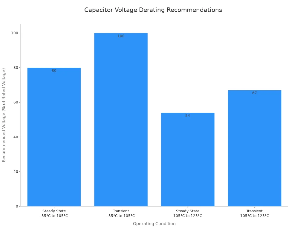
Properly decoding capacitor case markings and understanding why these ratings matter are fundamental skills. This knowledge helps you select the right polarized capacitors and ensures your electronics projects are safe and successful. Always double-check the capacitor marking codes and capacitor polarity before applying power.
Polarity and Other Key Info
Beyond capacitance and voltage, other markings on electrolytic capacitors provide critical information for safety and performance. This guide will help you with decoding capacitor case markings for polarity, temperature, and manufacturer details.
Polarity on Electrolytic Capacitors
You must install polarized capacitors with the correct orientation. The most important marking to find is for capacitor polarity. The primary visual cue is a prominent stripe, usually gray or white, running down the side of the capacitor. This stripe contains minus symbols (-) and always indicates the negative lead.
For new components, you have a secondary indicator:
- The longer lead is the positive (+) terminal.
- The shorter lead is the negative (-) terminal.
Connecting these parts backward is one of the main risks of incorrect capacitor polarity connection.
⚠️ Why Correct Polarity is a Must Reversing the capacitor polarity triggers a dangerous electrochemical reaction. The internal construction of these parts is asymmetrical. Applying a reverse voltage destroys the thin, insulating oxide layer that acts as the capacitor's dielectric. This creates a short circuit, causing the component to rapidly overheat, leak, or even explode.
While most radial capacitors use the stripe and lead length, other common capacitor polarity marking methods exist, especially for axial types where leads extend from opposite ends. You might see an arrow pointing to the negative lead or an indented band on the positive side. This is why understanding the risks of incorrect capacitor polarity connection is so vital.
Reading Temperature Ratings
You will also find a temperature rating printed on the capacitor, typically 85°C or 105°C. This number represents the maximum temperature the capacitor can safely operate at. While a standard 105°C capacitor is rated for an endurance lifetime of 2000 hours at that temperature, its actual lifespan dramatically increases in cooler conditions.
A key rule is that for every 10°C you reduce the operating temperature, the capacitor's life effectively doubles. A 105°C part running at a milder 85°C can last much longer than a standard 85°C part.
| Capacitor Type | Rated Endurance | Operating Temperature | Theoretical Lifespan |
|---|---|---|---|
| 85°C | 2000 hours | 85°C | 2000 hours |
| 105°C | 2000 hours | 105°C | 2000 hours |
| 105°C | 2000 hours | 95°C | 4000 hours |
| 105°C | 2000 hours | 85°C | 8000 hours |

Other Capacitor Case Markings
Finally, look for the manufacturer's name (like Nichicon or Rubycon) and a series code (e.g., "PW" or "HE"). These details are your key to finding the component's official datasheet online. While a simple capacitor value lookup is good for basic specs, the datasheet provides essential data for advanced or high-reliability circuits. Decoding capacitor codes for the series is crucial for this step.
You use the datasheet to find performance characteristics that are not printed on the part, such as:
- Equivalent Series Resistance (ESR): Low ESR is critical in power supplies.
- Ripple Current: The maximum AC current the capacitor can handle without overheating.
- Leakage Current: The small amount of DC current that "leaks" through the capacitor.
This information helps you choose the perfect replacement part, ensuring your project is both reliable and safe.
This guide helps you understand the markings on electrolytic capacitors. You can now confidently identify the most important specs on these polarized capacitors. Use this quick checklist for your next project.
- Capacitance Value: Look for the number followed by "µF".
- Rated Voltage: Find the number marked with a "V".
- Capacitor Polarity: Locate the stripe with minus signs (
-) for the negative lead.
⚠️ Final Safety Check You must always double-check the capacitor polarity before applying power. For polarized capacitors, choose a replacement with an equal or higher rated voltage. Using a part with a higher rated voltage can even extend its life. Never use a lower voltage part.
FAQ
Can I use a capacitor with a higher capacitance (µF)?
It depends. You should stick to the original value for timing or filter circuits. A small increase might be okay in power supply filtering, but a large change can cause problems. Always try to match the original capacitance value for best results.
Is it safe to use a capacitor with a higher voltage (V)?
✅ Yes! You can always use a capacitor with a higher voltage rating. It provides a better safety margin and can increase the component's lifespan. You must never use a capacitor with a lower voltage rating than the original part.
What happens if I install a capacitor backward?
You must always check the capacitor polarity. Installing it backward will destroy the component. This mistake causes a short circuit, leading to overheating, leaking, or even an explosion. Correct capacitor polarity is critical for safety and proper circuit function.
How do I know which lead is positive?
This guide helps you identify leads easily. The negative lead is marked with a stripe. Therefore, the other lead is the positive one. On new parts, the longer lead is positive. Always double-check the capacitor polarity before applying power.