Unlock the Secret to Measuring Inductors
You cannot use a standard multimeter to directly measure inductance. Your multimeter likely lacks a setting for this specific task. However, you can still measure inductance with your multimeter. This guide shows you how to calculate the inductance of unknown inductors. You will learn to measure values for projects, where a typical value might be around 10 milliHenries (mH).
Note: You just need your digital multimeter, a few common parts, and some simple math to measure any inductor. We will walk you through every step.
Key Takeaways
- You cannot directly measure inductance with a standard multimeter. You can calculate it using a simple circuit.
- Build an RL circuit with a resistor and the inductor. Measure AC voltages across each component.
- Use two formulas to calculate inductance. First, find inductive reactance. Then, use that to find the inductance.
- A continuity test checks if an inductor's wire is broken. It does not measure the actual inductance value.
- For very accurate inductance measurements, use a specialized LCR meter. It provides direct and precise readings.
How to Measure Inductance with an RL Circuit
This method uses a simple series circuit to help you calculate an unknown inductance. An RL circuit contains a resistor (R) and an inductor (L). When you apply an AC voltage, the inductor resists the change in current. This opposition is called inductive reactance. By measuring voltages in the circuit, you can find this reactance and then calculate the inductance.
Gather Your Tools
First, you need to collect a few essential components for this task. Having the right tools ready will make the process smooth and accurate.
- Digital Multimeter: You need a multimeter that can measure AC Voltage (V~) and Resistance (Ω).
- The Inductor: This is the component with the unknown inductance you want to measure.
- Known-Value Resistor: A resistor with a precise value is crucial. We recommend a 100Ω resistor with a 1% tolerance for good results.
- Stable AC Voltage Source: A function generator is the best choice. It provides a clean sine wave with a stable frequency, which you will need for the calculation. A good source should have a sufficient frequency and amplitude range.
- Connecting Wires: You will use these to build your circuit, likely on a breadboard.
How to Use a Multimeter for Resistance
Before building the circuit, you must measure the exact resistance of your resistor. A 100Ω resistor might not be exactly 100Ω due to its tolerance. Knowing its true value is key to an accurate inductance calculation. Here is how to use a multimeter to measure resistance:
- Turn your multimeter dial to the resistance setting (Ω). If your multimeter is not auto-ranging, start with a range slightly higher than the expected value, like 200Ω.
- Touch the multimeter probes firmly to each leg of the resistor.
- Read the value on the screen. If the display shows '1' or 'OL', the range is too low, so you need to select a higher one. If the reading is close to '0.00', the range is too high, and you should choose a lower one for better precision.
- Record this exact resistance value. You will use it in your final calculation.
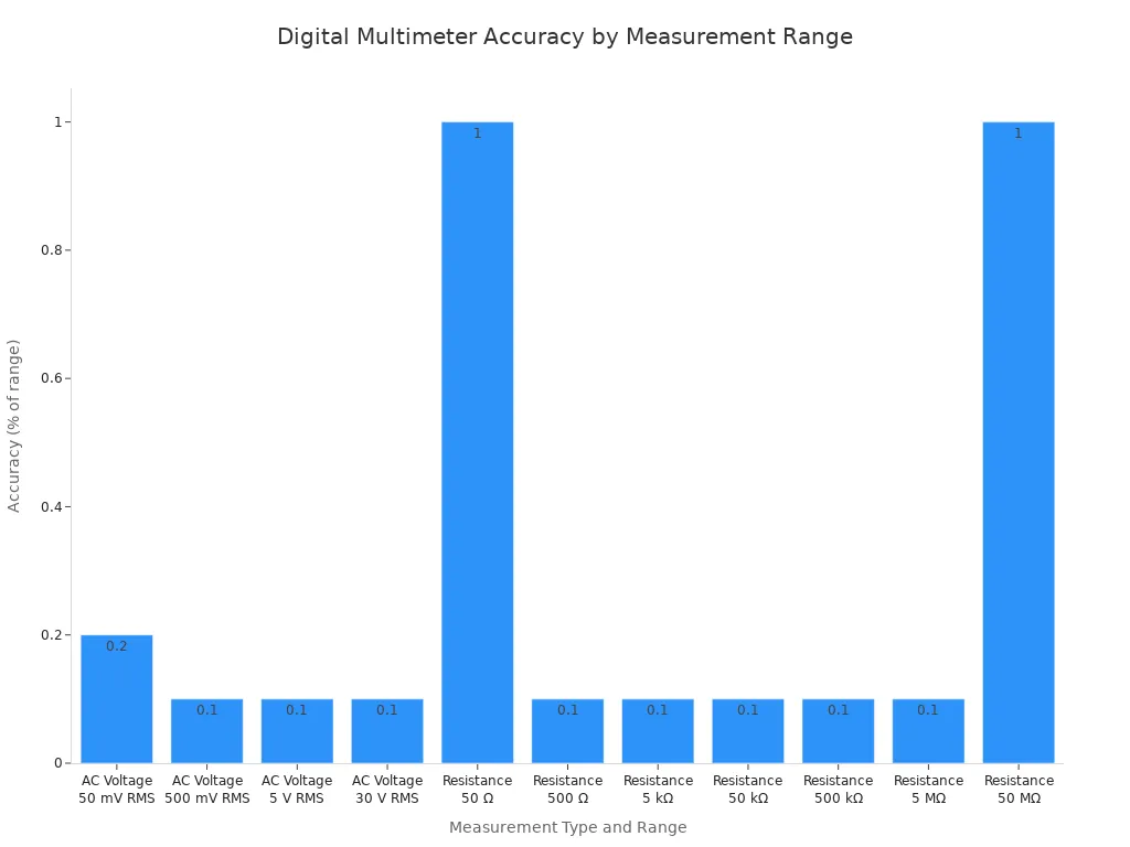
Accuracy Tip: The accuracy of your multimeter directly impacts your results. High-quality digital multimeters offer better resolution and accuracy across different measurement ranges. For example, a multimeter's accuracy can vary depending on the selected resistance range.
Build the Series Circuit
Now you will connect your components into a series circuit. In a series circuit, the components are connected end-to-end, creating a single path for the current to flow.
Connect your AC voltage source, the resistor (R), and the inductor coil (L) in a line. Ensure all connections are secure. If you use a breadboard, push the component leads in firmly to make good electrical contact. Double-check that no wires are loose or touching accidentally, which could create a short circuit.
Measure the AC Voltages
With your circuit built, it is time to use your multimeter to take some measurements. You will measure the AC voltage across the resistor and then across the inductor coil.
- Set your multimeter to measure AC voltage (often marked with a V and a wavy line ~).
- Turn on your AC voltage source. A frequency of 1,000 Hz (1 kHz) is a good starting point.
- Carefully place the multimeter probes across the two leads of the resistor to measure its voltage (VR). Write this value down.
- Next, move the probes and place them across the two leads of the inductor to measure its voltage (VL). Write this value down as well.
Note: Your multimeter has an internal resistance, called input impedance. This can slightly affect voltage readings in an AC circuit, a phenomenon known as the "loading effect." A multimeter with high input impedance (typically 10 MΩ) minimizes this error, helping you get a more accurate measurement. This is why a quality multimeter is important when you measure AC voltage.
Calculate Inductance
You now have all the values needed to calculate the inductance. The process involves two simple formulas.
Step 1: Calculate Inductive Reactance (X_L)
Inductive reactance (X_L) is the inductor's opposition to the AC current, and you measure it in Ohms (Ω). You can find it using the voltages you measured and the known resistance.
X_L = (VL / VR) * R
VL= Voltage across the inductorVR= Voltage across the resistorR= The exact resistance you measured earlier
Step 2: Calculate Inductance (L)
Once you have the inductive reactance, you can calculate the inductance (L). The unit for inductance is the Henry (H). The formula is:
L = X_L / (2 * π * f)
X_L= Inductive reactance you just calculatedπ(pi) ≈ 3.14159f= Frequency of your AC source in Hertz (Hz)
Example Calculation:
Let's walk through an example to see how it works.
- Your measured resistance (R) = 99.2 Ω
- Your AC source frequency (f) = 1,000 Hz
- You measure the voltage across the resistor (VR) = 2.1 V
- You measure the voltage across the inductor (VL) = 1.3 V
First, find the inductive reactance (X_L):
X_L = (1.3 V / 2.1 V) * 99.2 Ω
X_L ≈ 0.619 * 99.2 Ω
X_L ≈ 61.4 Ω
Now, use X_L to find the inductance (L):
L = 61.4 / (2 * 3.14159 * 1000 Hz)
L = 61.4 / 6283.18
L ≈ 0.00977 H
To make the number easier to read, you can convert it to milliHenries (mH) by multiplying by 1,000.
L ≈ 9.77 mH
By following these steps, you can successfully measure inductance using your multimeter and a few basic parts. This technique empowers you to identify and verify inductors for all your electronics projects.
Test Inductors with a Multimeter
Sometimes you do not need to measure the exact inductance of a component. You just need to know if it works at all. This simple continuity test helps you quickly check an inductor's health. It is a "go/no-go" check that tells you if the wire inside is broken. This test will not measure the inductance value, but it is a fast way to find a failed part.
The Continuity Go/No-Go Test
Think of this test as a simple question: is the wire inside the inductor coil complete, or is it broken? A continuity test sends a tiny electrical current through the component. If the current makes it from one end to the other, the multimeter beeps. This "go" result means the wire is intact. If the wire is broken, you get a "no-go" result, and the multimeter stays silent. This method is a great first step before you try to measure inductance.
Set Up for Continuity
You must prepare your multimeter correctly to get a reliable result. Follow these steps to set up your multimeter for the test.
- Turn off all power to the component. Unplug any circuits and remove any batteries.
- Plug the black probe into the COM port on your multimeter. Plug the red probe into the port marked with a V or Ω.
- Turn the multimeter dial to the continuity setting. This mode often shares a spot with resistance (Ω) and is marked with a symbol that looks like sound waves: 🔊.
- Test your setup. Touch the metal tips of the two multimeter probes together. Your multimeter should beep and display a value close to zero. This confirms your multimeter is ready to measure.
Check the Inductor
Now you are ready to test the component. Touch one multimeter probe to each lead of the inductor.
- Good Inductor: If the inductor coil is intact, your multimeter will beep. The screen will show a very low resistance value, usually just a few ohms.
- Bad Inductor: If the wire inside is broken, the multimeter will not beep. The screen will display 'OL', which stands for "Open Loop."
Important Limitation: A continuity test cannot find every problem. A working inductor will show continuity, but this does not reveal shorted turns inside the component. These shorts can significantly change the true inductance, even if the multimeter beeps. This is why you must measure inductance for precise work, while this test is best for quick checks on various inductors.
Key Factors for an Accurate Measurement
You can get a good estimate of inductance with a multimeter. However, a few factors can affect your results. Paying attention to these details helps you get a more precise measurement. This makes your efforts to measure inductance more successful.
Why Resistor Choice Matters
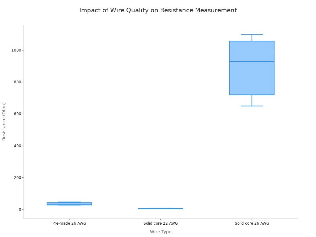
The accuracy of your resistor directly impacts your final inductance calculation. A resistor with a low tolerance (like 1%) gives you a more reliable starting point. Your connecting wires and breadboard contacts also add extra resistance. Poor quality connections can introduce significant errors. This unwanted resistance alters the voltage drops in your circuit and leads to an incorrect inductance value. You should use solid, high-quality wires to get a better measurement. The chart below shows how much resistance can vary between different wire types. You can see that some wires add much more resistance than others. A good multimeter helps you measure these small but important values.
The Role of AC Frequency
The frequency of your AC source is very important. An inductor's opposition to current, its reactance, is directly proportional to the frequency. This means if you increase the frequency, the reactance and the inductor's voltage drop also increase.
Pro Tip 💡: A good starting point is 1,000 Hz (1 kHz). For the best results, you can adjust the frequency. Change it until the voltage you measure across the inductor is half of the total voltage. This point gives you the most accurate inductance calculation. Your multimeter can easily measure these voltage changes.
When to Use an LCR Meter
The multimeter method is great for hobbyists. However, professionals often need more precision. For high-frequency circuits or quality control, you need a dedicated LCR meter. An LCR meter is a specialized device built to measure inductance, capacitance, and resistance. Measuring with an LCR meter is faster and much more accurate.
An LCR meter can measure how inductors behave at specific operating frequencies. This is critical in RF and high-speed digital circuits. Your multimeter cannot see these complex behaviors. So, when you need to measure inductance with the highest accuracy, measuring with an LCR meter is the best choice. An LCR meter is an essential tool for serious electronics design. Measuring with an LCR meter removes the guesswork. The LCR meter provides a direct reading of the inductance. A multimeter is a general tool, but the LCR meter is a specialist for inductance.
You can successfully calculate an inductor's inductance with your standard multimeter. You now have two great methods to test your components.
- RL Circuit Method: This technique lets you measure the exact value.
- Continuity Test: This is a quick go/no-go check using your multimeter.
This skill is a valuable addition to your electronics toolkit. You can confidently measure unknown inductance for any project. Your multimeter is a powerful device, and this knowledge makes your multimeter an even better tool to measure with.
FAQ
Why can't my multimeter measure inductance?
Your standard multimeter does not have the specific circuits to measure inductance. You can calculate inductance with a multimeter, but for a direct reading of inductance, you need a specialized lcr meter. An lcr meter is built for this.
When is an lcr meter better for inductance?
You should use an lcr meter for precise work. 🔬 An lcr meter gives a more accurate inductance value than the multimeter method. This is vital for professional designs where the correct inductance matters most.
Does the multimeter continuity test measure inductance?
No, this test does not measure inductance. Your multimeter only checks for a complete wire. It gives no data about the actual inductance value. For a true inductance measurement, you need an lcr meter.
What is the main difference between an lcr meter and a multimeter?
A multimeter is a versatile tool for general measurements. An lcr meter is a specialist device you use to get a direct and precise reading. A standard multimeter cannot provide this function.