Easy Method to Measure Resistance with a Meter

You can check resistance with a meter by setting your multimeter to the resistance mode and connecting the probes to the component. Always pay attention to safety and simplicity. Many beginners make mistakes such as placing probes incorrectly, using the wrong function setting, or not checking for damaged leads. Reliable tutorials and step-by-step guides help you learn how to check resistance with a meter without prior experience. Follow each step carefully for accurate results.
- Check probe placement before measuring.
- Inspect leads to avoid shocks.
- Set the dial to resistance mode.
Key Takeaways
- Always turn off the power before measuring resistance. This step protects you and your multimeter from damage.
- Check probe placement and inspect leads for damage. Proper setup ensures accurate readings and prevents safety hazards.
- Use the correct multimeter settings. Set the dial to resistance mode (Ω) and select the appropriate range for accurate measurements.
- Isolate the component before testing. Disconnect it from the circuit to avoid interference from other parts.
- Store your multimeter properly after use. Keep it in a cool, dry place to maintain its accuracy and prolong its lifespan.
Safety First
Power Off
Before you measure resistance, always turn off the power to the circuit. This step keeps you safe and protects your multimeter. Never try to measure resistance on a live circuit. You risk electric shock and can damage your meter.
Tip: Double-check that the circuit is not live before you begin.
Common safety incidents include:
- Electric shock from measuring resistance on live circuits.
- Damage to the multimeter if voltage is present.
- Injuries from high current events, such as burns or arc flashes.
You should disconnect the power and verify the circuit is de-energized. This action protects both you and the equipment.
Discharge Components
Some components, like capacitors, can store energy even after you turn off the power. If you touch them without discharging, you may get shocked or burned. Large capacitors can hold enough energy to cause serious harm.
- Capacitors can keep a charge after disconnection.
- Touching charged capacitors may result in shocks, burns, or even fires.
- Discharge capacitors before measuring to remove any leftover energy.
Always use a resistor or a proper discharge tool to safely release stored energy. This step reduces the risk of accidental electrocution or damage.
Safe Handling
Handle your multimeter and test leads with care. Use the right configuration for your measurement. For resistances over 100 kΩ, use a 2-wire setup. For lower values, use a 4-wire setup. Shielded cables help prevent noise when measuring high resistance.
| Best Practice | Description |
|---|---|
| Use 2-wire or 4-wire configuration | Choose based on resistance value for accurate results. |
| Use Offset Compensated Ohms | Reduces errors from thermal EMFs or offset voltages. |
| Use Offset Nulling | Subtracts zero reading to improve accuracy. |
| Account for Cable Resistance | Consider cable effects, especially for multiple measurements. |
| Use Shielded Cables for High Resistance | Prevents noise when measuring above 100 kΩ. |
| Shield Resistor Under Test | Reduces noise for resistances above 10 MΩ. |
Stay alert and follow these best practices. You will keep yourself safe and get reliable results every time.
Getting Ready
Tools Needed
You need the right tools to measure resistance accurately. The most important tool is a digital multimeter. This device lets you check resistance, voltage, and current. Many models offer extra features that make your work easier.
Here are some popular multimeter models and their features:
| Multimeter Model | Features |
|---|---|
| Klein Tools MM400 | Measures continuity and resistance, includes thermocouple probe. |
| AstroAI 6000 | Auto-ranging, handy magnetic hanging strap. |
| Fluke 117 | Integrated probe holders, optional magnetic hanging strap. |
| Greenlee DM-45 | Hold, min, max functions, backlight available. |
| Etekcity MSR-C600 | Auto-ranging, includes backlight. |
| Crenova MS8233D | Auto-ranging, suitable for various measurements. |
| Neoteck NT8233D Pro | Auto-ranging, multiple measurement functions. |
You also need a pair of test leads. These leads connect the multimeter to the component you want to test. Make sure the leads have no cracks or exposed wires. Damaged leads can give false readings or cause injury.
Tip: Always check your multimeter’s battery before starting. A weak battery can affect your results.
Some kits include extra accessories, such as alligator clips or carrying cases. These items help you work more safely and keep your tools organized.
Workspace Setup
Set up your workspace before you begin. Choose a flat, clean surface with good lighting. This helps you see small parts and read the multimeter display clearly.
Keep your tools within reach. Place your multimeter, test leads, and any components you plan to measure on the table. Remove any clutter that could get in the way.
Safety comes first. Avoid working near water or in damp areas. Dry hands and a dry surface prevent accidents. If you work with sensitive electronics, use an anti-static mat to protect your components.
A tidy workspace helps you focus and reduces mistakes. You will find it easier to measure resistance when everything is in order.
Check your setup one more time before you start. Good preparation leads to accurate and safe measurements.
How to Use a Multimeter
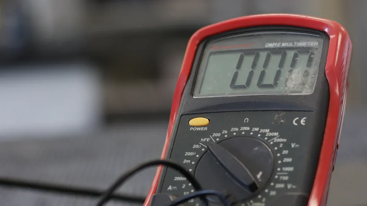
Set to Ohms
You need to set your multimeter to the correct mode before you start measuring resistance. Most digital multimeters have a dial or selector switch. Turn this dial to the symbol that looks like the Greek letter omega (Ω). This symbol stands for ohms, which is the unit for resistance. Always switch off the power supply to the circuit first. You should also discharge any capacitors and isolate the component you want to test.
Here is a simple comparison of steps for digital and analog meters:
| Step | Digital Multimeter | Analog Multimeter |
|---|---|---|
| 1 | Switch off the power supply to the circuit. | Switch off the power supply to the circuit. |
| 2 | Discharge any capacitors. | Discharge any capacitors. |
| 3 | Isolate the component. | Isolate the component. |
| 4 | Turn the multimeter ON. | Turn the multimeter ON. |
| 5 | Set the selector to resistance (Ω). | Set the selector to resistance (Ω). |
| 6 | Select a suitable range. | Select a suitable range. |
| 7 | Insert probes into the correct sockets. | Insert probes into the correct sockets. |
| 8 | Connect leads across the component. | Connect leads across the component. |
| 9 | Note the reading and adjust range for accuracy. | Note the reading and adjust range for accuracy. |
| 10 | Turn the selector to voltage mode after use. | Calibrate the meter before connecting leads. |
You should select a suitable range if your multimeter does not have auto-ranging. If you choose a range that is too high, the reading may be less accurate. If you choose a range that is too low, the display may show “OL” or overload.
Tip: Always check your multimeter’s battery before you begin. A weak battery can cause incorrect readings.
Insert Leads
You must insert the test leads into the correct sockets on your multimeter. Take the black lead and plug it into the COM jack. Take the red lead and plug it into the VΩ jack. Make sure the leads are fully inserted and not loose.
Follow these steps for using a multimeter:
- Plug the black probe into the COM port.
- Plug the red probe into the V/Ω port.
- Set the dial to measure resistance (Ω).
- Test the multimeter by touching the probes together. The display should read zero ohms or beep if your meter has a continuity feature.
You should always check the probes for damage before using a multimeter. Damaged leads can give false readings or cause safety issues. When using a multimeter, keep the component isolated from other parts of the circuit. This step helps you get an accurate measurement.
Note: The position of the test leads does not matter when measuring resistance. You can connect them in either direction.
You now know how to use a multimeter to set the correct mode and insert the leads. Using a multimeter in this way helps you measure resistance safely and accurately.
How to Check Resistance with a Meter
Connect Probes
You can start measuring resistance by connecting the probes to the component you want to test. This step is important in learning how to check resistance with a meter. Follow these steps to connect the probes correctly:
- Insert the black probe into the COM port on your multimeter.
- Insert the red probe into the port marked with the "Ω" symbol.
- Make sure the multimeter dial is set to the "Ω" setting.
- Remove the component, such as a resistor, from the circuit if possible. This helps you measure resistance without interference from other parts.
- Place one probe on each end of the component. You can use either probe on either side because resistance does not have polarity.
- Ensure the probes touch the metal leads of the component firmly. Good contact gives you an accurate reading.
Tip: Always disconnect the component from the circuit before measuring resistance. This prevents other components from affecting your results.
If you want to know how to check resistance with a meter safely, always make sure the circuit is not live and the component is isolated.
Read Display
Once you connect the probes, look at the multimeter display. The screen will show a number and the "Ω" symbol. This number tells you the resistance value. Understanding the display is a key part of how to check resistance with a meter.
Here is a table to help you understand common symbols on the display:
| Symbol | Meaning |
|---|---|
| Ω | Resistance measurement |
| OL | Over limit (resistance too high to measure) |
| Continuity | Electrical connection (may beep if connected) |
- If you see a number and the "Ω" symbol, you have measured the resistance successfully.
- If the display shows "OL," the resistance is too high for the selected range or the circuit is open.
- If the display shows zero or close to zero, the component may have very low resistance or the probes are touching each other.
Note: The multimeter starts measuring resistance as soon as you connect the probes. If you see "OL" before connecting, this is normal. It means the circuit is open.
You use the display to check if your measurement is correct. If you see "OL" or zero, check your connections and make sure the component is not damaged.
Adjust Range
Some multimeters have an auto-ranging feature. This means the meter picks the best range for you when you measure resistance. If your multimeter does not have auto-ranging, you need to select the range manually. Knowing how to check resistance with a meter includes understanding how to adjust the range for accurate results.
- Press the "Range" button or turn the dial to select a higher or lower range.
- Start with the highest range if you do not know the expected resistance. Lower the range until you get a clear reading.
- If you see "OL," the resistance is higher than the selected range. Move to a higher range.
- If you see zero or a very low number, try a lower range for better accuracy.
Tip: Dirt, oil, or touching the metal part of the probes with your fingers can affect your measurement. Always keep the probes and component clean.
When measuring resistance, always remove the component from the circuit for the best results. Body contact with the test leads can add extra resistance and change the reading.
Here are some common errors and how to avoid them:
| Error Description | Prevention Method |
|---|---|
| Measuring resistance on a live circuit | Always check for voltage before measuring resistance. |
| Ignoring lead resistance in low resistance tests | Use the meter's offset or relative mode to cancel out lead resistance. |
| Misreading "OL" or zero | Make sure the probes are connected properly and the range is set correctly. |
| Noise or interference | Keep the component and probes clean and avoid touching the metal parts. |
Learning how to check resistance with a meter helps you avoid these mistakes and get accurate results every time. When you measure resistance, always pay attention to the display and adjust the range as needed. This process is the foundation of measuring resistance with a multimeter.
Measuring Resistance Tips
No Polarity Needed
When you measure resistance with a multimeter, you do not need to worry about which probe goes where. A resistor does not have polarity. You can place the red probe on one side and the black probe on the other, or switch them. The reading on your multimeter will stay the same. This makes your job easier and helps you avoid mistakes. You can focus on getting a good connection with the probes. The multimeter checks the resistance by sending a small current through the component. The direction does not matter for this test.
Tip: If you ever feel unsure, remember that the multimeter will give the same result no matter how you hold the probes on a resistor.
You can use this method for most basic components, like resistors and wires. The multimeter will always show the correct resistance value. You do not need to swap the probes or check for positive and negative sides. This rule helps you save time and avoid confusion.
Avoid Live Circuits
You must never use a multimeter to measure resistance on a live circuit. This mistake can cause serious harm. The multimeter is not designed to handle voltage when set to resistance mode. If you try to measure resistance while the circuit has power, you put yourself and your equipment at risk.
Here are some dangers you face if you measure resistance on a live circuit:
| Risk Type | Description |
|---|---|
| Electrical Shock | Can cause severe burns, loss of balance, and involuntary movements. |
| Electrocution | Refers to severe injury or fatal consequences from electric shock, with risks increasing with current. |
| Arc Flash | A significant electrical explosion that can reach temperatures up to 19,000C, causing severe burns. |
| Arc Blast | Creates a pressure wave that can throw individuals and objects, leading to potential injuries. |
| Burn Injuries | Varying degrees of burns can occur, posing significant health hazards to individuals in the vicinity. |
You should always turn off the power before using your multimeter to check resistance. This step keeps you safe and protects your multimeter from damage. Many accidents happen because people forget this rule. You can avoid these risks by double-checking that the circuit is off. The multimeter will work best and last longer if you use it only on circuits without power.
Always check for voltage before you measure resistance. Your safety comes first.
How to Test a Resistor
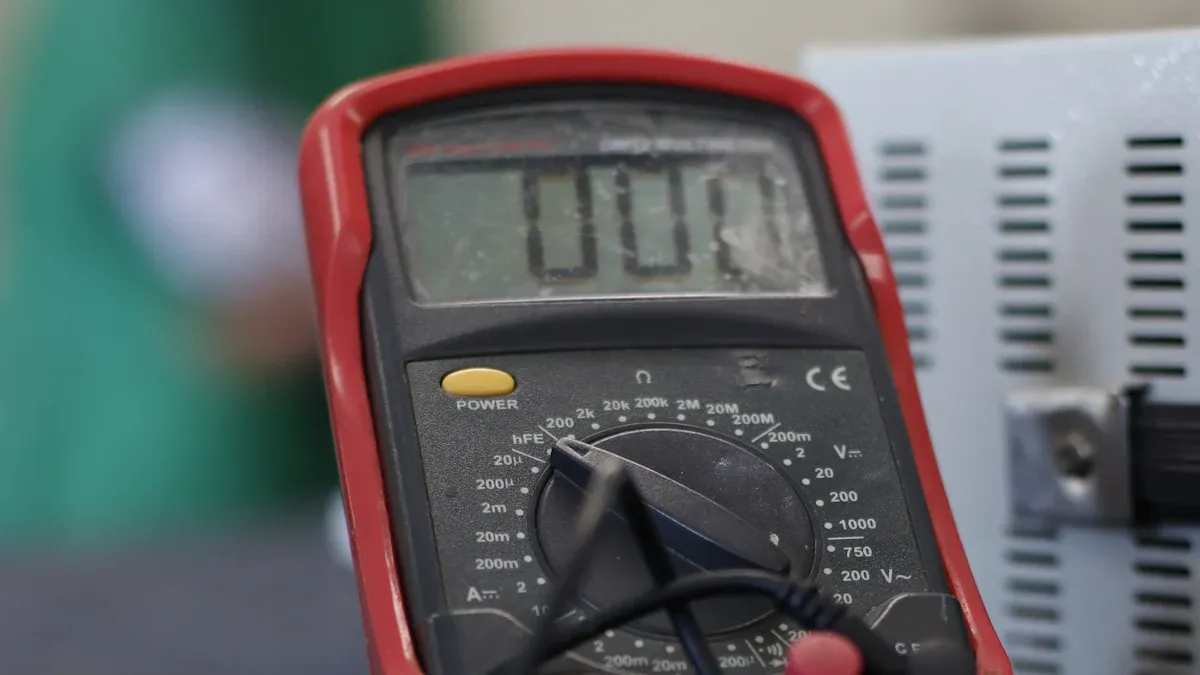
Remove from Circuit
You need to follow a clear process when learning how to test a resistor. Start by making sure the power is off. Unplug the device or remove the batteries. Some devices can hold a charge for several minutes, so wait before touching anything. Safety comes first in testing resistors.
Next, isolate the resistor. You should disconnect one end of the resistor from the circuit. It does not matter which end you choose. Pull the resistor gently if it is not soldered. If the resistor is soldered, use a soldering iron to melt the solder. Use needle nose pliers to pull the resistor free. This step helps you avoid measuring other parts of the circuit. You want to measure only the resistor itself.
Here is a simple checklist for how to test a resistor:
- Turn off power and wait for any stored charge to disappear.
- Disconnect one end of the resistor from the circuit.
- Remove the resistor carefully if it is soldered.
Tip: Always check that the resistor is fully isolated before testing resistors. This step gives you the most accurate results.
Compare Values
After you remove the resistor, you can begin testing resistors with your multimeter. Place the probes on each end of the resistor. Read the resistance value on the display. You need to compare this value to the resistor’s specifications.
Resistor color bands help you identify the value and tolerance. Each color stands for a number. The bands show the resistance and how much it can vary. For small resistors, color codes are easier to read than printed numbers. You can also check the datasheet for exact values.
Resistors come in standard values. Manufacturers include a tolerance, which means the actual resistance can be higher or lower than the stated value. For example, a 1kΩ resistor with a ±20% tolerance can measure anywhere from 800Ω to 1200Ω. When you learn how to test a resistor, you must understand these limits. If your measured value falls within the tolerance range, the resistor works as expected.
You should also look for special codes. The letter "k" means kilohms. The letter "K" shows a 10% tolerance. Knowing these codes helps you compare your results to the specifications.
| Color Band | Value | Tolerance |
|---|---|---|
| Red | 2 | |
| Orange | 3 | |
| Gold | ±5% | |
| Silver | ±10% |
Note: Always compare your measured resistance to the color code or datasheet. This step is key in testing resistors and ensures you get reliable results.
You now know how to test a resistor by removing it from the circuit and comparing the measured value to its specifications. Testing resistors in this way helps you find faulty components and keep your projects working.
Interpreting Results
Normal Readings
When you measure resistance, you want to see a value that matches the expected range for your component. Most common resistors follow international standards set by the IEC in 1952. These standards, called the E-series, help manufacturers produce resistors with values that work well together. You can trust that resistors from different brands will match if they use these standard values.
Standard resistor values use a logarithmic scale. This means the numbers increase in steps that make sense for electrical designs. You can find resistors with different tolerance levels. Tolerance tells you how much the actual resistance can differ from the labeled value. For example, a 5% tolerance means the real resistance can be 5% higher or lower than what is printed.
Here is a table showing typical resistance ranges for common resistors:
| Tolerance | Resistance Range (Ω) |
|---|---|
| 1% | 10.0 to 1.00 MΩ |
| 2% | 10.0 to 1.00 MΩ |
| 5% | 10.0 to 1.00 MΩ |
| 10% | 10.0 to 1.00 MΩ |
- Standard resistor values make it easy to replace parts.
- You can check the color bands or datasheet to find the expected value.
- If your reading matches the expected value within the tolerance, your resistor works well.
📝 Tip: Always compare your measured value to the resistor’s color code or datasheet.
“OL” or Zero
Sometimes, your multimeter shows “OL” or zero when you measure resistance. These readings tell you something important about the component.
- “OL” stands for “open loop” or “over limit.” This means the resistance is too high for your meter to measure, or the component is open (broken inside).
- A zero reading means the component has almost no resistance. For a resistor, this could mean it is shorted or damaged.
If you see “OL” or zero, follow these steps:
- Check if the component is disconnected or broken.
- Inspect for visible damage, like burns or cracks.
- Make sure your multimeter is set to the correct mode.
- Test the leads by touching them together. The meter should show zero or beep.
If your meter shows “OL” before you connect the probes, this is normal. It means the meter is ready to measure.
You can use these results to decide if a component needs replacing or if your circuit has a problem. Always double-check your setup to avoid mistakes.
Troubleshooting
Inconsistent Readings
You may notice that your resistance readings change or seem unreliable. This problem can happen for several reasons. You should check for unwanted voltages in the circuit. These voltages can cause the reading to jump, especially if you reverse the leads. Always disconnect all power sources and discharge any capacitors before you measure.
Semiconductors like diodes and transistors can also affect your results. These components may change the reading depending on the direction of current. If you suspect this, try removing the semiconductor from the circuit and test again.
Loose connections often cause fluctuating readings. You should inspect all wires and connections. Fix any that seem loose or damaged. Large capacitors may take time to stabilize. Hold the probes in place until the reading stops changing.
Inductance can make auto-ranging meters unstable. Switch to a fixed ohms range if you see the numbers jumping. A low battery in your meter can also cause erratic readings. Replace the battery if you notice this issue.
Here is a table that shows common causes and solutions:
| Cause | Description | Cure |
|---|---|---|
| Unwanted voltages | Reading changes if leads are reversed | Disconnect power and discharge capacitors |
| Semiconductors | Diodes/transistors affect readings | Remove semiconductors for accurate measurement |
| Capacitance | Large capacitors slow to stabilize | Hold leads until reading stabilizes |
| Loose connections | Fluctuating readings due to bad wiring | Fix wiring and connections |
| Inductance | Auto-ranging meters unstable with large inductance | Use fixed ohms range |
| Low battery | Erratic readings from weak battery | Replace battery |
🛠️ Tip: Always check your meter’s battery and connections before you start measuring.
Meter Issues
Your multimeter can sometimes give you trouble during resistance measurements. You should always make sure the circuit is powered off. If you measure resistance in a live circuit, you may get incorrect readings.
When you test components in a circuit, you might measure the resistance of other connected parts. Isolate the component for the most accurate result. If you work with large capacitors, your meter may show a closed circuit at first. This happens because the capacitor charges briefly.
You can use special features on your meter to improve accuracy. The null offset feature helps remove errors from wires and connections. The auto zero function compensates for internal offsets, making your readings more reliable.
- Power off the circuit before measuring resistance.
- Isolate the component to avoid measuring extra resistance.
- Wait for large capacitors to stabilize before reading.
- Use null offset to reduce connection errors.
- Enable auto zero for better accuracy.
🔍 Note: If your readings still seem off, check the meter’s manual for troubleshooting steps. You can solve most problems by following these simple checks.
Using a Multimeter Best Practices
Turn Off After Use
You should always turn off your multimeter when you finish measuring resistance. This simple habit helps you in several ways. When you leave the multimeter on, the battery drains quickly. A dead battery means your multimeter will not work when you need it. You also lower the risk of accidental overload or short circuits by turning off the device.
- Turn off your multimeter after every use to save battery life.
- Make it a habit to check the power switch before putting the multimeter away.
- Turning off the multimeter keeps it ready for your next project.
🛑 Tip: If you forget to turn off your multimeter, the battery may run out. Always double-check before storing it.
You should also inspect your multimeter for any signs of wear and tear. Look at the display, buttons, and test leads. Clean the probes and remove any dust or debris. A clean multimeter gives you more accurate readings and lasts longer.
Store Properly
Proper storage keeps your multimeter safe and accurate. You should store your multimeter in a cool, dry place. Avoid direct sunlight and extreme temperatures. Heat and moisture can damage the internal parts of your multimeter.
- Use a protective case to prevent scratches and impacts.
- Keep your multimeter away from chemicals and magnetic fields.
- Store the multimeter in a dust-free environment.
A good storage spot helps your multimeter stay reliable for years. You should avoid places with moisture or strong magnets. These can affect the accuracy of your resistance measurements. Always keep your multimeter and its accessories together in one place. This way, you will not lose any important parts.
📦 Note: A clean, dry, and organized storage area helps your multimeter work well every time you use it.
You can follow these best practices to make sure your multimeter stays in top condition. Good habits now will help you get accurate results and keep your multimeter working for a long time.
You can measure resistance safely and accurately with your multimeter by following a few simple steps. Always turn off power before you use your multimeter. Plug the black lead into the common jack and the red lead into the resistance jack. Set your multimeter to the resistance setting. Touch the probes across the component and read the display. Start with the lowest setting on your multimeter and switch ranges if you see “OL.” Practice using your multimeter and double-check your results. You will gain confidence with each test. Anyone can master resistance measurement with a multimeter.
Remember to turn off your multimeter after testing to save battery life.
FAQ
How do you know if your multimeter is working correctly?
You can test your multimeter by touching the probes together. The display should show zero ohms or beep. If you see no response, check the battery and leads. Replace damaged parts before using your multimeter.
Can you measure resistance without removing a component from the circuit?
You should remove the component before using your multimeter. Other parts in the circuit can affect the reading. Isolating the component gives you the most accurate resistance measurement.
What does “OL” mean on a multimeter display?
“OL” stands for “over limit.” Your multimeter cannot measure the resistance because it is too high or the circuit is open. Try changing the range or check if the component is disconnected.
Why does your multimeter show zero resistance?
Your multimeter shows zero resistance when the probes touch each other or the component has a short. If you see zero on a resistor, it may be damaged. Always check the leads and the component before testing.
How often should you replace your multimeter battery?
You should replace your multimeter battery when the display dims or readings become unreliable. Check the battery every few months. A fresh battery helps your multimeter give accurate results.