How to Find the Equivalent Capacitance of Parallel Circuits
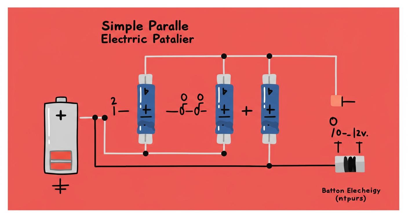
You can find the equivalent capacitance for a parallel circuit with a simple calculation. The total equivalent capacitance is the sum of each individual capacitor value. You use this fundamental formula:
C_eq = C1 + C2 + C3 + ...
This means you just add the value of each capacitor to find the total capacitance. The final equivalent capacitance of the capacitor group will be larger than any single capacitor.
Pro Tip 💡: This simple math helps you calculate the total equivalent capacitance needed to stabilize voltage in power supplies. This makes calculating capacitance in parallel straightforward for any project.
Key Takeaways
- You find the total capacitance of parallel circuits by adding the values of all individual capacitors.
- The total capacitance in a parallel circuit is always larger than any single capacitor in that group.
- Always convert all capacitor values to the same unit before you add them to avoid mistakes.
- Capacitors in parallel increase the total area for storing charge, which makes the total capacitance higher.
- Each capacitor in a parallel circuit has the same voltage across it.
Calculating Total Capacitance: A Guide
Calculating the total capacitance for capacitors in parallel is a simple, three-step process. You can master this skill quickly. This guide walks you through each step to find the equivalent capacitance of your circuit.
Step 1: Identifying Capacitors in Parallel
First, you need to identify which capacitors are connected in parallel. Look at your circuit diagram or physical circuit board. Capacitors are in parallel when both of their leads connect to the same two points in the circuit. Imagine two parallel lines in a drawing; the tops of the lines connect, and the bottoms of the lines connect. This setup is the key visual cue for a parallel connection. Each capacitor in the group shares the same voltage source.
Step 2: Listing Individual Values
After you identify the parallel group, your next task is to find the value of each individual capacitor. You will find this information marked directly on the capacitor's body. However, manufacturers use several different coding systems.
A large electrolytic capacitor might clearly print its value, like "100µF". Smaller ceramic or film capacitors often use a compact code because of their size.
Reading the Code 🧑💻 You must correctly interpret the markings on each capacitor to get an accurate value. A common method is the three-digit code, where the value is always in picofarads (pF).
Here are the most common ways to read a capacitor value:
- Direct Marking: The value and unit are printed directly on the component (e.g., "10µF" or "47nF").
- Three-Digit Code: The first two numbers are the significant digits, and the third is a multiplier (the power of 10). For example, a capacitor marked "104" means 10 x 10⁴ pF, which equals 100,000 pF or 100 nF.
- Letter Codes: Sometimes, a letter like 'p', 'n', or 'u' is used in place of a decimal point. For instance, "4n7" means 4.7 nF.
You also need to be aware of tolerance, which tells you how much the actual capacitance can vary from its marked value. This is often shown with a letter.
Here is a quick reference table to help you decipher these codes:
| Code Type | Example | Meaning |
|---|---|---|
| 3-Digit Value | 103 | 10 x 10³ pF = 10,000 pF = 10 nF |
| 3-Digit Value | 224 | 22 x 10⁴ pF = 220,000 pF = 220 nF |
| Tolerance | J | ±5% tolerance |
| Tolerance | K | ±10% tolerance |
| Tolerance | M | ±20% tolerance |
Make a list of each capacitor's value. Ensure all values are in the same unit (e.g., all in microfarads, µF) before you move to the next step. This preparation prevents errors in your final calculation of the total equivalent capacitance.
Step 3: Summing the Capacitances
This final step is the easiest. You will now calculate the total equivalent capacitance. To find the total capacitance in parallel, you simply add the values of all the individual capacitors together.
You use the formula we introduced earlier:
C_eq = C1 + C2 + C3 + ...
Here, C_eq represents the equivalent capacitance, and C1, C2, and C3 are the values of each capacitor in the parallel group.
For example, if you have three capacitors with values of 10µF, 22µF, and 47µF, your calculation is:
Total = 10µF + 22µF + 47µF = 79µF
The resulting sum is your circuit's total equivalent capacitance. This simple addition is the core of calculating capacitance in parallel. The final total will always be greater than the largest single capacitor in the group.
Calculating Equivalent Capacitance: Examples

Now you understand the three-step process. Let's apply it to some practical examples. Seeing the math in action will solidify your understanding. You will find calculating the equivalent capacitance is a useful skill for many projects. You often need this calculation for designing circuits like:
- Timing circuits
- Energy storage systems
Two-Capacitor Circuit
Let's say you have two capacitors connected in parallel.
- Capacitor 1 (C1) = 10µF
- Capacitor 2 (C2) = 22µF
To find the total capacitance, you apply the simple addition formula.
- Identify the individual capacitances: C1 = 10 µF, C2 = 22 µF
- Apply the parallel capacitance formula:
C_eq = C1 + C2 - Substitute the values:
C_eq = 10 µF + 22 µF - Calculate the total capacitance:
C_eq = 32 µF
The equivalent capacitance for this circuit is 32µF.
A Note on Tolerance ⚙️ Each capacitor has a manufacturing tolerance, often ±10% or ±20%. This means its actual value can vary. When you add capacitors, their tolerances can accumulate. Engineers must account for these variations. For a hobbyist, knowing this helps you understand why a circuit might behave slightly differently than expected. The final equivalent capacitance can deviate from the nominal calculated value.
Multi-Capacitor Circuit
The same rule applies no matter how many capacitors you have. You just add them all together. Using multiple smaller capacitors in parallel instead of one large capacitor can offer engineering advantages.
- Multiple smaller capacitors often have a lower total Equivalent Series Resistance (ESR).
- This lower ESR can lead to a faster response time in certain circuits.
Imagine a circuit with three capacitors in parallel.
- C1 = 100nF
- C2 = 470nF
- C3 = 220nF
You calculate the total equivalent capacitance by summing these values.
C_eq = C1 + C2 + C3
C_eq = 100nF + 470nF + 220nF
C_eq = 790nF
The total for this group is 790nF. The process remains simple addition.
Mixed Unit Conversion
You will often work with a capacitor marked in microfarads (µF) next to one marked in nanofarads (nF). You must convert all values to the same unit before you add them. Adding 1µF and 500nF directly will give you an incorrect answer.
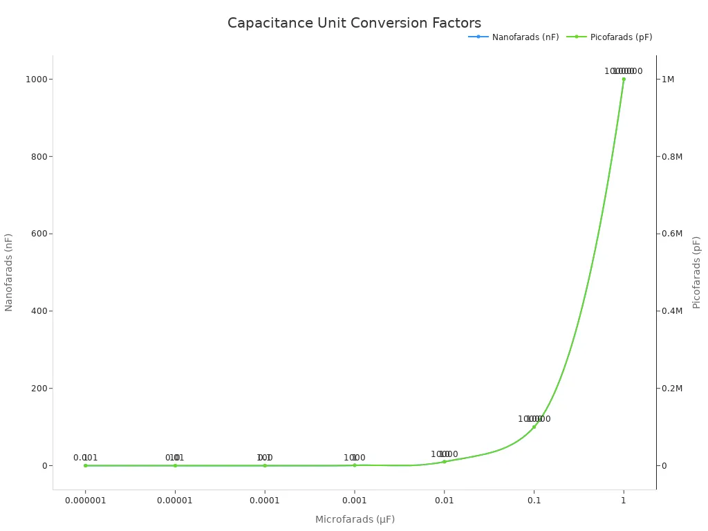
The most common units are microfarads (µF), nanofarads (nF), and picofarads (pF). Here is a quick conversion table.
| Microfarads (µF) | Nanofarads (nF) | Picofarads (pF) |
|---|---|---|
| 1 µF | 1000 nF | 1,000,000 pF |
| 0.1 µF | 100 nF | 100,000 pF |
| 0.01 µF | 10 nF | 10,000 pF |
| 0.001 µF | 1 nF | 1,000 pF |
Let's calculate the total for a 1µF capacitor in parallel with a 500nF capacitor.
- List the values: C1 = 1µF, C2 = 500nF.
- Convert to a common unit. Let's use nanofarads (nF). We know that
1µF = 1000nF. - Add the converted values. Now you can find the total capacitance.
C_eq = 1000nF + 500nFC_eq = 1500nF
The equivalent capacitance is 1500nF. You could also express this total as 1.5µF. This step is critical for accuracy when dealing with capacitance in parallel.
The 'Why' Behind Capacitance in Parallel
You know that adding capacitors in parallel is simple, but why does it work that way? Understanding the physics behind the formula helps you become a better circuit designer. The simple addition rule for capacitance in parallel comes down to two key ideas: a larger area for storing charge and a constant voltage for every capacitor.
Increased Effective Plate Area
Think about what a basic capacitor is: two conductive plates separated by a non-conductive material (a dielectric). The capacitance of a capacitor depends directly on the surface area of these plates.
The Formula for Capacitance 🔬
Capacitance = k * ε₀ * (Area / Separation)In this formula, a larger plateArearesults in a higher capacitance value.
When you connect capacitors in parallel, you essentially combine their plate areas. Imagine you have two books. Placing them side-by-side gives you a larger total surface area than one book alone. Connecting each capacitor this way effectively creates one large "super capacitor" with a much bigger plate area. This combined surface area allows the system to store a greater amount of charge at the same voltage. The result is a higher total or effective capacitance for the circuit. Each capacitor contributes its full storage ability to the group.
Constant Voltage and Charge Summation
The second reason the formula works involves voltage and charge. In a parallel circuit, every component connects to the same two points. This means the voltage across each capacitor is identical.
- Each capacitor is connected directly to the voltage source.
- This allows every capacitor to store charge independently.
- The total charge stored by the group is the sum of the charges on each individual capacitor.
You can express this relationship with a simple equation:
Q_total = Q1 + Q2 + Q3 + ...
Since the charge Q on any capacitor is its capacitance C times the voltage V (Q = C * V), we can substitute this into the equation. Because voltage (V) is the same for every capacitor, the math looks like this:
C_eq * V = (C1 * V) + (C2 * V) + (C3 * V) + ...
You can then divide V from both sides of the equation. This leaves you with the familiar formula for total capacitance.
Handling Combined Series-Parallel Circuits

Real-world circuits often mix series and parallel connections. You can solve these complex circuits by breaking them down into smaller, manageable parts. The strategy is to simplify the circuit one step at a time until you are left with a single total equivalent capacitance.
Identifying Parallel Sections
Your first job is to look at the circuit diagram and find small, simple groups of components. You need to spot which parts are purely in series or purely in parallel.
- Parallel: Look for any capacitor group where the leads for each capacitor connect to the same two points.
- Series: Look for any capacitor group connected end-to-end in a single path.
You will tackle these small sections one by one. This approach turns a confusing circuit into a series of simple problems.
Calculating Section by Section
Once you identify a group, you calculate its equivalent capacitance. You use the correct formula for that section.
Remember the Rules 📝
- For a parallel section, you add the values:
C_eq = C1 + C2 + ...- For a series section, you use the reciprocal formula:
1/C_eq = 1/C1 + 1/C2 + ...
After you calculate the value for a group, you can redraw the circuit in your mind. You replace that entire group with a single, imaginary capacitor of the calculated value. Your circuit diagram becomes simpler with each step. You repeat this process until only one final capacitor value remains.
Finding the Final Total
After simplifying all the series and parallel sections, you will perform one last calculation. This gives you the final total equivalent capacitance for the entire circuit. Finding this total value is often the main goal. For a deeper analysis, engineers use this total capacitance to understand the whole circuit's behavior.
Once you have the final equivalent capacitance, a full circuit analysis involves these steps:
- Calculate the equivalent capacitance of the entire circuit.
- Determine the total charge (
Q) stored using the formulaQ = C_eq × V, whereVis the total voltage. - Work backward from the total to find the specific charge and voltage for each individual capacitor.
This method allows you to understand how every capacitor in a complex network functions.
You now know how to find the equivalent capacitance for capacitance in parallel. The main rule is simple: the total capacitance is the sum of each individual capacitor. This gives you the total equivalent capacitance for the circuit.
Key Takeaway 📝 The formula for the equivalent capacitance is:
C_eq = C1 + C2 + C3 + ...
This formula shows that the final equivalent capacitance is always larger than any single capacitor in the group. This total is the opposite of how resistors behave. Calculating the equivalent capacitance for each capacitor is a fundamental skill.
FAQ
Why is total capacitance larger in parallel?
You create a larger effective plate area when you connect capacitors in parallel. This larger area allows the entire group to store more charge. More charge storage means a higher total capacitance for your circuit.
What happens to the voltage in a parallel capacitor circuit?
Each capacitor in a parallel circuit receives the same voltage. The leads of every capacitor connect to the same two points of the power source. This ensures a constant voltage across all components in the group.
Is one big capacitor better than many small ones?
Sometimes, multiple small capacitors are better. They can have a lower total resistance (ESR) and react faster. This design choice helps you fit capacitance into tight spaces or improve circuit performance.
Design Tip ⚙️ Using several small capacitors can also be cheaper than one large, specialized capacitor.
How is this different from resistors in parallel?
Capacitors in parallel add up, making the total larger. Resistors in parallel behave the opposite way. Their total resistance becomes smaller than the smallest individual resistor. You use different formulas for each component.