Bridge Rectifier Circuit Build Your Own in Easy Steps

You want to convert alternating current (AC) into direct current (DC). This guide helps you build a functional bridge rectifier circuit using simple steps on a breadboard. You will soon have a working circuit and understand how to test its DC output.
Many electronics you use daily need this conversion. This rectifier circuit is the heart of power supplies for devices like:
- Televisions
- Computers
- Mobile phone chargers
Your full-wave circuit is more efficient and creates a better DC output than other methods.
| Rectifier Type | Efficiency Characteristic |
|---|---|
| Half-wave | Lower efficiency, utilizes only half of the AC cycle |
| Full-wave | More efficient, converts the entire AC cycle into DC |
Key Takeaways
- A bridge rectifier changes AC electricity into DC electricity, which many electronics need.
- You need four diodes, a transformer, a capacitor, and a resistor to build this circuit.
- Connect the diodes in a special way to form a bridge, then add the transformer for power.
- A capacitor helps make the DC output smooth and steady, like a flat line.
- Test your circuit with an LED and a multimeter to make sure it works correctly.
Components for Your Rectifier Circuit
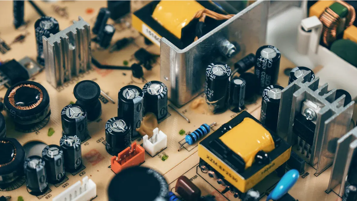
You need a few common parts to build your rectifier circuit. Gathering everything first makes the assembly process smooth and easy. This list covers the electronic components and the tools you will use.
Required Electronic Components
You will find these parts at most electronics stores or online. They are the building blocks of your project.
- Diodes (x4): You need four 1N4007 diodes. A diode allows electricity to flow in one direction. The 1N4007 diode is a great choice. It can handle up to 1000V and 1A of current. You can use a higher-numbered diode like the 1N4007 in place of a lower one, but not the other way around.
| Diode Model | Peak Reverse Voltage (PRV) |
|---|---|
| 1N4001 | 50V |
| 1N4004 | 400V |
| 1N4007 | 1000V |
- AC Transformer (x1): This steps down the high voltage from your wall outlet. A low-voltage transformer, such as one that converts 120V AC to 24V AC, is perfect for this breadboard circuit.
- Smoothing Capacitor (x1): You need one electrolytic capacitor (1000µF, 35V). This capacitor smooths the pulsating DC from the rectifier. The capacitor stores and releases energy. This action by the capacitor makes the output voltage more stable. The capacitor is vital for a clean DC signal.
- Load Resistor (x1): A 1kΩ resistor limits the current.
- LED (x1): A standard LED will show that your circuit works.
- Breadboard and Jumper Wires: These let you build the circuit without soldering. The capacitor, diode, and other parts plug right in.
Note: The smoothing capacitor is polarized. It has a positive and a negative lead. Your capacitor must be connected correctly to work. The capacitor will help your rectifier provide a steady output. The capacitor is a key part of this power supply circuit.
Essential Assembly Tools
You only need a few tools for this project. Safety and accuracy are most important.
- Digital Multimeter: You need this to test your circuit. A good beginner multimeter has auto-ranging to select the correct measurement range for you. It should also have a clear display and a continuity test function.
- Wire Strippers/Cutters: You will use these to prepare your jumper wires.
- Soldering Iron (Optional): You do not need this for a breadboard build. However, you might want one to make your rectifier circuit permanent later. Always place the hot iron on its stand. Work in a well-ventilated area to avoid fumes.
Building the Diode Bridge Rectifier
You are now ready to assemble the core of your power supply. This section guides you through building the full wave bridge rectifier on your breadboard. You will see how four simple diodes work together to transform AC into DC.
The Full Wave Bridge Rectifier Design
The full wave bridge rectifier design is elegant and efficient. It uses four diodes arranged in a closed-loop or square shape. This specific arrangement is the key to converting the entire AC waveform into a usable DC output. The full wave rectifier is superior to other methods.
| Feature | Half-Wave Rectifier | Full-Wave Rectifier |
|---|---|---|
| AC Signal Used | Only one half of the AC wave | Both halves of the AC wave |
| DC Output Level | Lower average voltage | Higher average voltage |
| Output Pulses | One pulse per AC cycle | Two pulses per AC cycle |
This full wave rectifier circuit works in two stages that follow the AC input cycle:
- During the positive half-cycle, two specific diodes become forward-biased. They allow current to pass through them. The other two diodes are reverse-biased and block current.
- During the negative half-cycle, the roles reverse. The other pair of diodes becomes forward-biased and conducts current.
This clever process flips the negative half of the AC wave into a positive one. The result is a pulsating DC voltage. This output flows in only one direction but its voltage level rises and falls. For a 60Hz AC input, your full wave rectifier produces a DC ripple with a frequency of 120Hz. This makes the output from the full wave bridge rectifier much easier to smooth into a steady DC voltage.
Placing the Diodes on the Breadboard
Proper diode placement is critical for your full wave bridge rectifier to work. You must pay close attention to the orientation of each diode.
Identify Your Diode's Polarity 🔎 Each
diodehas two leads: an anode (positive) and a cathode (negative). You can easily identify the cathode by the silver or grey stripe on the diode's body. Current flows from the anode to the cathode.
Follow these steps to build the diode bridge rectifier:
- Step 1: Take two diodes. Place them in series on the breadboard. Connect the cathode (striped end) of the first
diodeto the anode (plain end) of the seconddiode. - Step 2: Take your other two diodes. Create another pair just like the first one. Connect the cathode of the third
diodeto the anode of the fourthdiode. - Step 3: Now, position the two
diodepairs on the breadboard to form thebridgeshape. Connect the anodes of the first and third diodes together. This junction will be one of your AC input points. - Step 4: Connect the cathodes of the second and fourth diodes together. This junction will be your positive
DCoutput.
Avoid these common mistakes:
- Placing a
diodein the wrong row or orientation. - Accidentally shorting a
diodewith a misplaced wire.
The Peak Inverse Voltage (PIV) of a diode is the maximum reverse voltage it can handle without damage. Your diode's PIV rating must be higher than the peak voltage of your AC input. This is why the 1N4007 diode is an excellent choice for this full wave rectifier circuit.
Connecting the AC Power Source
With your diode bridge rectifier assembled, you can now connect the AC power. You will use the two output wires from your AC transformer.
Safety First! ⚠️ Always connect power lines as the final step. Before you plug in the transformer, double-check all your connections with your multimeter to prevent short circuits that could damage your components.
- Connect one AC wire from the transformer to the junction where the two
diodeanodes meet. - Connect the other AC wire to the junction where the two
diodecathodes meet.
Your full wave bridge rectifier now has its AC input. The circuit is ready to perform the rectification. This setup ensures the full wave rectifier can process both halves of the AC cycle.
Establishing the DC Output
The final step in building the full wave bridge rectifier is to establish the DC output points. These are the terminals where you will get your converted DC power.
- Positive (+) DC Output: This is the point where the cathodes of two diodes connect. In our build, this is the junction from Step 4 of the placement section.
- Negative (-) DC Output: This is the point where the anodes of the other two diodes connect. This is the junction from Step 3 of the placement section.
When the full wave rectifier operates, current always flows through two diodes at any time. Each silicon diode causes a small voltage drop. The theoretical forward voltage drop is about 0.6 V to 0.7 V per diode. Since two diodes are always in the path, you can expect a total drop of around 1.2 V to 1.4 V from your full wave bridge rectifier.
You can calculate the expected DC output voltage of your rectifier circuit with a simple formula:
Vdc = (Vrms * √2) - (2 * Vd)
Vdcis your finalDCoutputvoltage.Vrmsis your transformer's ACoutputvoltage.Vdis the forward voltage drop of onediode(use 0.7V).
For example, with a 24V AC transformer, the peak voltage is 24 * √2 ≈ 33.9V. After the diode drops (2 * 0.7V = 1.4V), your DC output will be approximately 32.5V. This calculation helps you understand the output of your full wave rectifier circuit. Your diode bridge rectifier is now complete.
Finalizing and Testing Your Circuit
Your diode bridge is built. Now you will add the final components to create a smooth DC output and test your work. This stage transforms your full wave rectifier circuit from a concept into a functional power supply.
Adding a Smoothing Capacitor
The output from your full wave rectifier is a pulsating DC. You need to smooth this ripple. You will use a smoothing capacitor for this job. These components are also known as smoothing or reservoir capacitors.
The smoothing capacitor connects in parallel with the DC output of the full wave rectifier. When the rectifier voltage rises, the capacitor charges and stores energy. As the rectifier voltage falls, the capacitor discharges. This action fills in the gaps between the voltage pulses, which greatly reduces the ripple. The result is a much more stable DC output. The full wave rectifier with smoothing capacitor design is standard in power supplies.
Warning: Connect the Capacitor Correctly! ⚠️ Your electrolytic smoothing capacitor is polarized. You must connect the positive lead to the positive DC output of the bridge and the negative lead to the negative output. Reversing the polarity will cause hydrogen gas to build up inside the capacitor. This can make the capacitor fail, bulge, or even explode.
To achieve a specific bridge rectifier ripple voltage, you can calculate the needed capacitance. A simple formula is C = Current / (2 x AC Frequency x Vripple). For this project, our 1000µF capacitor is a great choice for smoothing the output.
Connecting a Load Resistor and LED
You need a load to test your full wave rectifier circuit. An LED with a current-limiting resistor is a perfect visual load. The LED will light up, showing that your full wave rectifier is producing a DC output.
First, you must calculate the correct resistor value to protect the LED. You can use this formula:
Resistor (Ω) = (Source Voltage - LED Voltage) / LED Current (A)
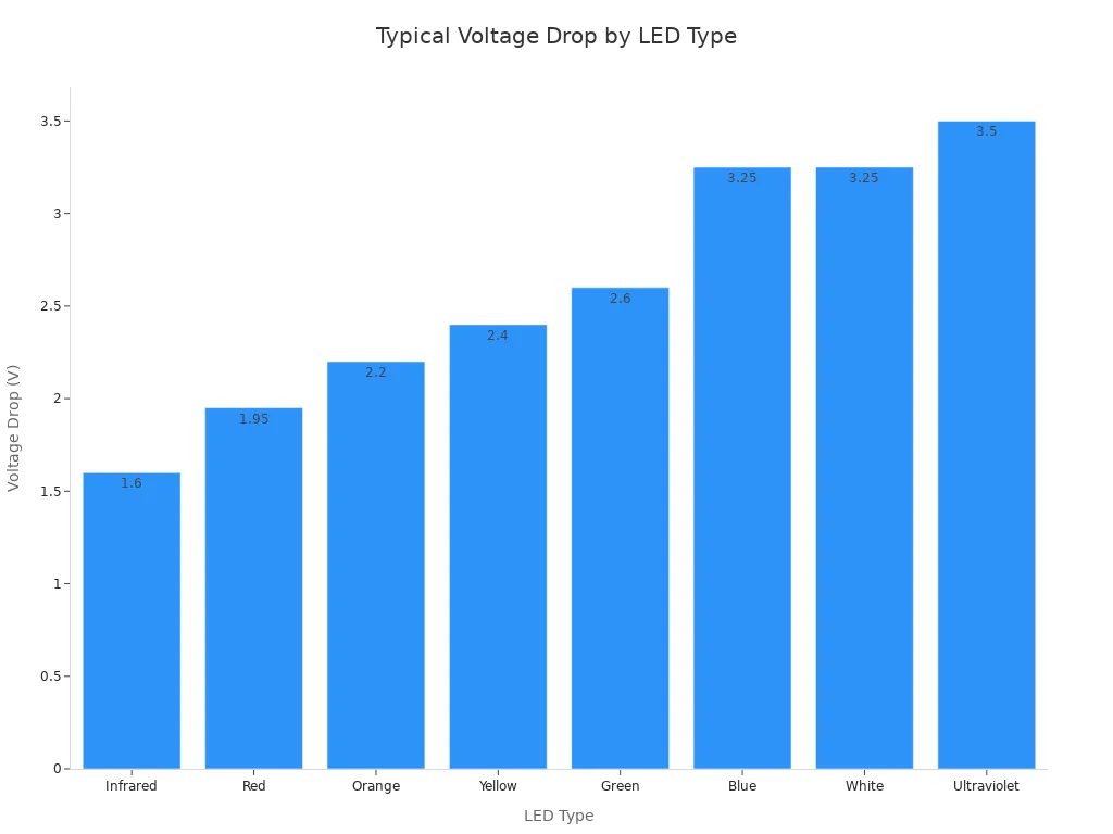
A standard red LED has a voltage drop of about 2V. We will aim for a current of 20mA (0.020A). If your DC output is around 32V, the calculation is (32V - 2V) / 0.020A = 1500Ω. A 1.5kΩ resistor is ideal, but a 1kΩ resistor will also work and make the LED brighter.
- Connect your resistor and LED in series.
- Connect this pair across the DC output of the full wave rectifier, after the smoothing capacitor.
- Ensure the LED's longer lead (anode) connects toward the positive side of the bridge and the shorter lead (cathode) connects toward the negative side.
Confirming Full Wave Rectifier Output
Before you apply power, perform a final check.
- Visual Inspection: Look for any loose wires or incorrect diode and capacitor connections.
- Resistance Check: Use your multimeter to check the resistance across each diode. A good diode should show low resistance in one direction and very high resistance in the other.
Now you can test the live circuit.
- Set your multimeter to measure DC voltage (Vdc).
- Plug in your transformer. The LED should light up.
- Place the multimeter probes across your DC output terminals (across the LED and resistor).
You should see a stable average DC output voltage. This reading confirms your full wave rectifier with smoothing capacitor is working correctly. The full wave rectifier output waveform is now a nearly flat line, which is the goal of a good DC power supply. This stable average DC output is ready to power other small electronics.
Congratulations on building your full wave rectifier. You assembled the diode bridge and added a smoothing capacitor. The smoothing capacitor provides smoothing for the DC output. Your full wave rectifier now has a low ripple DC output. The smoothing capacitor is key for ripple smoothing. This rectifier provides a stable DC output.
You learned how a full wave rectifier converts AC to DC. The smoothing capacitor is vital for ripple smoothing. The capacitor ensures a clean output. The smoothing capacitor provides excellent smoothing for the DC output, reducing ripple. The capacitor gives a great output. The capacitor provides smoothing. The capacitor reduces ripple. The capacitor gives a clean output. The capacitor provides smoothing. The capacitor reduces ripple. The capacitor gives a clean output. The capacitor provides smoothing. The capacitor reduces ripple. The capacitor gives a clean output. The capacitor provides smoothing. The capacitor reduces ripple.
This rectifier is a great power supply.
FAQ
What should I do if my LED does not light up?
You should first check your connections. Ensure each diode's striped end (cathode) is placed correctly. Also, confirm the smoothing capacitor and LED are not backward. A multimeter's continuity test can help you find broken connections.
Can I use a transformer with a different voltage?
Yes, you can use a different transformer. You must choose a capacitor with a voltage rating higher than the transformer's peak output. You also need to recalculate the value for your current-limiting resistor to protect the LED.
Why is my DC output voltage lower than the transformer's peak voltage?
Your circuit uses two diodes at any time to rectify the AC. Each silicon diode causes a small voltage drop of about 0.7V. This results in a total drop of around 1.4V from your expected peak DC voltage.
How can I make the DC output even smoother?
A larger capacitor provides better smoothing. For the best smoothing and a perfectly stable voltage, you can add a voltage regulator IC, like a 7812, after your capacitor. This creates a professional-grade power supply.