How the L298N Motor Driver Controls Your DC Motors
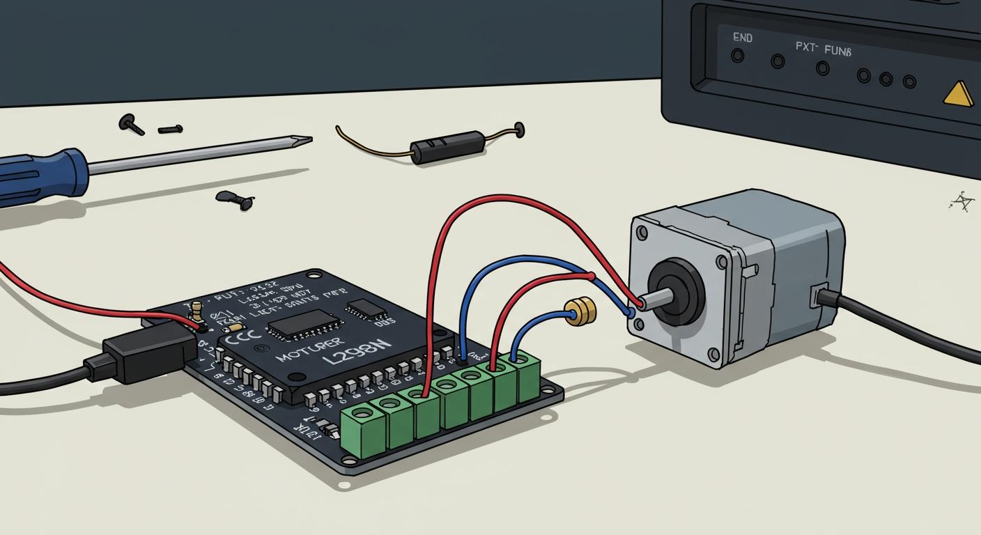
You have a powerful tool in the L298N motor driver module. This popular dual H-bridge driver lets you control the speed and direction of a high-current DC motor from a low-current microcontroller. The L298N motor driver acts as the perfect bridge for your project. The L298N module handles the heavy power needs your motor demands. This L298N motor driver module gives you precise control over your DC motor.
This L298N module has impressive specifications for your DC motor.
| Specification | Value |
|---|---|
| Driving Voltage | 5V~24V |
| Continuous Working Current | 2A |
| Peak Instantaneous Current | 3A |
| Logic Voltage | 5V |
Note: The L298N uses a separate 5V logic supply. This allows the driver's internal brain to operate, enabling it to send current to the motor. Without this 5V signal, the L298N driver will not power your motor, giving you an extra layer of control over the motor's speed and direction.
Key Takeaways
- The L298N motor driver controls DC motor speed and direction. It acts as a bridge between a low-current microcontroller and a high-current motor.
- An H-bridge circuit in the L298N changes the motor's direction. It switches the flow of electricity through the motor.
- Pulse Width Modulation (PWM) controls motor speed. It rapidly turns power on and off, changing the average voltage the motor receives.
- Connect the L298N's ground to your Arduino and motor power supply. This common ground ensures proper communication.
- Remove the jumpers from the ENA and ENB pins to control motor speed. Connect these pins to PWM-capable pins on your microcontroller.
UNDERSTANDING THE L298N DUAL H-BRIDGE DRIVER
The L298N motor driver gets its power from a clever circuit called an H-bridge. This circuit is the key to how you control the direction of your DC motor. The "dual" in L298N dual H-bridge driver simply means the chip contains two identical H-bridge circuits. This feature allows you to control two DC motors independently with a single L298N module.
The L298N IC generates significant heat when driving a motor, especially under heavy loads. You will notice a metal heatsink attached to the L298N module. This component is essential for dissipating heat and preventing the driver from overheating, ensuring reliable performance.
How an H-Bridge Controls Direction
You can imagine an H-bridge as four electronic switches surrounding your motor. Let's label them S1, S2, S3, and S4. The motor sits in the middle of this "H" shape. To make the motor spin, you close two switches at a time, creating a path for electricity to flow through it.
- Forward Motion: You can achieve forward rotation by closing switches S1 and S4. This action allows current to flow through the motor from left to right, causing it to spin in one direction.
- Reverse Motion: To reverse the motor, you open S1 and S4, then close switches S2 and S3. This reverses the current's path, making it flow from right to left through the motor. This change in polarity makes the motor spin in the opposite direction.
This simple switching mechanism gives you complete control over the motor's direction. The L298N dual H-bridge driver manages these switches for you.
⚠️ Important Safety Note: Avoid "Shoot-Through" You must never close both switches on the same side of the H-bridge at the same time (e.g., S1 and S2 together). This creates a direct short circuit from your power supply to the ground. This condition, known as "shoot-through," can permanently damage the L298N driver and your power source. The L298N has internal logic to help prevent this.
Using the IN Pins for Direction
You control the H-bridge switches using the L298N motor driver's input pins, labeled IN1 and IN2 for the first motor (and IN3, IN4 for the second). You send signals from your microcontroller, like an Arduino, to these pins. The L298N driver interprets these signals to open and close the correct switches.
A signal can be either HIGH or LOW:
- A HIGH signal from a 5V Arduino is a voltage of about 3V to 5V.
- A LOW signal is a voltage close to 0V (typically below 1.5V).
The L298N logic circuitry uses these signals to control the direction of the motor. The following table shows how the driver responds to different combinations on the IN pins.
| IN1 | IN2 | Motor Action | Description |
|---|---|---|---|
| LOW | LOW | Brake | The motor stops quickly. Both motor terminals are connected to ground. |
| HIGH | LOW | Forward | The motor spins in the forward direction. |
| LOW | HIGH | Reverse | The motor spins in the reverse direction. |
| HIGH | HIGH | Brake | The motor stops quickly. Both motor terminals are connected to the positive supply. |
By setting the IN pins to HIGH or LOW, you tell the L298N dual H-bridge driver exactly what to do. This simple logic is the foundation for making your robot or project move. You gain precise control over your DC motor with just two digital signals.
SPEED CONTROL WITH THE L298N
You now know how to change the direction of your DC motor. That gives you basic movement, but true control comes from managing its speed. The L298N motor driver gives you this power using a technique called Pulse Width Modulation, or PWM. You can use L298N PWM to make your motor spin slowly, quickly, or at any speed in between. This section shows you how the L298N uses PWM signals to control the speed of your motor.
What is Pulse Width Modulation (PWM)?
Pulse Width Modulation (PWM) is a clever way to control the speed of a DC motor. Instead of changing the voltage level, you switch the power to the motor on and off very quickly. The L298N driver does this thousands of times per second. Your motor responds to the average voltage it receives, which you control by changing how long the power stays on versus off.
To understand L298N PWM, you need to know three key terms:
- Period: This is the total time it takes for one complete on-and-off cycle of the PWM signal.
- Frequency: This measures how many cycles happen per second, expressed in Hertz (Hz). The L298N can handle a range of frequencies.
- Duty Cycle: This is the most important part for speed control. It describes the percentage of time the signal is 'on' during one period.
The duty cycle directly sets the average power your motor gets. A higher duty cycle means the power is on longer, resulting in a higher average voltage and a faster motor speed. A lower duty cycle means the power is on for a shorter time, leading to a lower average voltage and a slower motor.
Imagine you are sending a 12V signal to the L298N motor driver.
- A 75% duty cycle means the signal is ON for 75% of the time. The motor acts as if it's getting about 9V and spins quickly.
- A 50% duty cycle means the signal is ON for half the time. The motor sees an average of 6V and spins at a medium speed.
- A 25% duty cycle means the signal is ON for only 25% of the time. The motor gets an average of 3V and spins slowly.
By adjusting the duty cycle, you gain precise PWM control over your motor's speed and direction.
Pro Tip: Choosing the Right PWM Frequency When you use L298N PWM, you might hear a high-pitched whining sound from the motor. This happens when the PWM frequency is in the range of human hearing. To eliminate this noise, you can set the frequency above 20,000 Hz (20 kHz). However, very high frequencies can sometimes cause the motor to operate with a slight jitter. For most DC hobby motors, a frequency between 1 kHz and 10 kHz gives you smooth performance without the annoying sound.
The Role of the Enable Pin
The L298N module has special pins that let you control the speed: ENA for Motor A and ENB for Motor B. These "Enable" pins act like a master switch for each motor. When the Enable pin is HIGH, the motor is on. When it is LOW, the motor is off, no matter what the IN pins are telling the driver to do. The L298N uses this function to achieve speed control.
💡 Action Required: Remove the Jumpers! Your L298N motor driver module likely has small plastic caps, or jumpers, on the ENA and ENB pins. These jumpers connect the Enable pins directly to the 5V supply. This keeps the motors enabled all the time, forcing them to run at full speed. To control the speed, you must remove these jumpers.
Once you remove the jumper, you connect the ENA (or ENB) pin to a PWM-capable pin on your microcontroller. Now, instead of sending a steady HIGH signal, you send a PWM signal. The L298N driver interprets this rapid on-off signal. The duty cycle of your PWM signal effectively tells the L298N how often to "enable" the motor within each tiny time slice. This is how you control the speed of the DC motor.
The table below shows how the Enable pin works with the IN pins for one motor.
| ENA Pin Signal | IN1 | IN2 | Motor Action |
|---|---|---|---|
| LOW (or 0% PWM) | Any | Any | Motor is OFF (free spinning) |
| HIGH (or 1-100% PWM) | LOW | LOW | Brake (stops quickly) |
| HIGH (or 1-100% PWM) | HIGH | LOW | Forward (speed set by PWM) |
| HIGH (or 1-100% PWM) | LOW | HIGH | Reverse (speed set by PWM) |
By combining the IN pins for direction and a PWM signal on the Enable pin, the L298N gives you full control over your motor's speed and direction. This powerful L298N PWM capability is what makes the driver so useful for robotics and other projects.
PRACTICAL L298N WIRING GUIDE
You are now ready to connect your L298N motor driver and bring your project to life. This guide gives you the essential steps for wiring the power, your motor, and the Arduino for complete control. Following these connections correctly ensures your L298N with DC motor setup works safely and reliably.
Connecting Power and the Motor
Properly powering your L298N module is the first critical step. The driver needs two voltages: one for the motor and one for its internal logic. You will connect your motor to the green screw terminals labeled OUT1 and OUT2.
The L298N has a pin labeled +12V for your motor power supply (Vs) and a +5V pin for the logic. A small jumper on the module controls an onboard 5V regulator. Your motor's voltage determines how you should configure this jumper.
- If your motor power supply is between 6V and 12V: Keep the jumper installed. The onboard regulator will convert the motor voltage to 5V to power the driver's logic. The
+5Vpin will act as an output, which you can use to power your Arduino. - If your motor power supply is greater than 12V: You must remove the jumper. This action protects the L298N's onboard regulator from damage. You will need to provide a separate, stable 5V supply to the
+5Vpin to power the driver's logic.
Crucial Connection: Common Ground You must connect the ground (GND) pin of the L298N to the ground of your Arduino and the ground of your motor power supply. This creates a shared reference point. Without a common ground, the control signals from your Arduino will not be understood by the L298N driver, leading to unpredictable motor behavior.
Arduino Control Connections
With power sorted, you can connect the control pins. These connections allow your Arduino to tell the L298N with DC motor what to do. For one DC motor, you will use three pins: IN1, IN2, and ENA.
- Connect the L298N
IN1andIN2pins to any two digital pins on your Arduino (e.g., pins 8 and 7). These will set the motor's direction. - Connect the L298N
ENApin to a PWM-capable pin on your Arduino (marked with a~, like pin 9). This connection gives you speed control over the DC motor.
The following Arduino code demonstrates how to control one DC motor. This example makes the motor run forward at half speed, then reverse at full speed.
// Define the L298N control pins for Motor A
const int enA = 9; // Must be a PWM pin for speed control
const int in1 = 8;
const int in2 = 7;

void setup() {
  // Set all motor control pins as outputs
  pinMode(enA, OUTPUT);
  pinMode(in1, OUTPUT);
  pinMode(in2, OUTPUT);
}

void loop() {
  // --- Move Forward at Half Speed ---
  // Set direction to forward
  digitalWrite(in1, HIGH);
  digitalWrite(in2, LOW);
  // Set speed to half (127 is approx. 50% of 255)
  analogWrite(enA, 127);
  delay(2000); // Run for 2 seconds

  // --- Move Reverse at Full Speed ---
  // Set direction to reverse
  digitalWrite(in1, LOW);
  digitalWrite(in2, HIGH);
  // Set speed to full (255 is 100%)
  analogWrite(enA, 255);
  delay(2000); // Run for 2 seconds

  // --- Stop the Motor (Brake) ---
  digitalWrite(in1, LOW);
  digitalWrite(in2, LOW);
  delay(1000); // Wait for 1 second
}
This simple setup for the L298N with DC motor gives you powerful and precise motor control. You can now command your DC motor to move how you want, when you want.
You now understand how the L298N motor driver gives you complete control over your DC motor. The L298N driver combines two key functions. You use the H-bridge logic for direction and a PWM signal to control the speed. This powerful L298N PWM combination makes the L298N module an essential tool for any DC motor project. Mastering this H-bridge driver unlocks new possibilities. You can now manage your motor's speed and direction, giving you the power to build amazing things. The L298N PWM helps you control the speed of your motor. This H-bridge driver gives you control over your motor.
🚀 Your Next Step: You have mastered the L298N driver! This control over your DC motor opens up a world of possibilities in robotics and mechatronics. Go build something incredible with your motor.
FAQ
Can I control a stepper motor with the L298N?
Yes, you can. The setup for an l298n with stepper motor uses both H-bridges of the driver. Each H-bridge controls one coil of the stepper motor. This application of l298n gives you precise control over the motor's steps, which is great for a DC motor project requiring accuracy.
Why is my motor or driver getting hot?
Your motor or driver can overheat from excessive current. This happens if your DC motor draws more power than the driver can handle. Ensure your motor's current rating is below 2A. A large DC motor requires a more powerful driver. The driver also gets warm during normal motor operation.
What are some common applications for this driver?
You can find a great application for this driver in many projects. The most common application of l298n is in small robots where you control two DC motors for movement. You can also use the driver for any DC motor that needs speed and direction control, like in automated systems.
Can I power my Arduino from the L298N driver?
You can power your Arduino from the driver if your motor power supply is between 6V and 12V. Keep the 5V regulator jumper on the driver. The +5V pin on the driver will output a stable 5V, which can power your board. This simplifies your DC motor wiring.
What happens if my DC motor needs more than 2A?
You should not use a DC motor that needs more than 2A continuously. The l298n driver has a 2A limit per channel. Exceeding this limit will cause the driver to overheat. This can permanently damage the driver and potentially your connected DC motor.