How Do Relays Work The Complete Answer
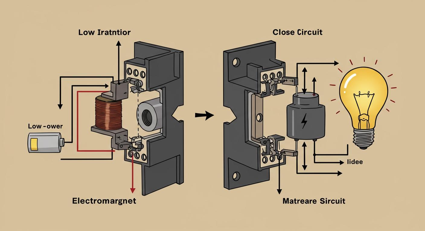
So, how does a relay work? A relay is an electrically operated switch. Think of this relay as a remote control for your circuits. You use a small current to create an electromagnet inside the relay. This is how a relay works: the magnet flips a switch in a separate, high-power circuit. These versatile relays provide crucial electrical isolation, letting you safely control heavy loads. The market for relays continues to expand, showing their importance in modern electronics.

Key Takeaways
- A relay is an electric switch. It uses a small electric signal to turn a separate, more powerful circuit on or off.
- Relays work by using a small current to create a temporary magnet. This magnet then moves a switch inside the relay.
- Relays have a coil, contacts, and an armature. The coil creates the magnetic field, the armature moves, and the contacts open or close the main circuit.
- There are different types of relays. Some have moving parts, and others use electronics. Each type works best for different jobs.
- Always choose the right relay for your project. Match its voltage and current ratings to your circuit to keep it safe and working well.
HOW DOES A RELAY WORK?
Understanding how a relay works is simple when you break it down into a four-step process. At its heart, a relay uses the principles of electromagnetism to physically move a switch. Let's walk through each step of the cycle, from turning the relay on to turning it off.
ENERGIZING THE COIL
The process begins when you apply a small electrical current to the control circuit. This current flows into a tightly wound coil of wire inside the relay. The flow of electricity through the wire instantly creates a magnetic field, turning the coil into a temporary magnet. This is the core principle behind an electromagnet.
The strength of this magnetic field is not random. It directly depends on the amount of current you send and the number of wire turns in the coil.
Physics gives us a way to calculate this strength. For a simple circular coil, the magnetic field (B) is found using the formula:
B = (μ₀ * N * I) / (2 * r)
Here,
Nis the number of turns,Iis the current, andris the radius of the coil. This shows that more turns or more current results in a stronger magnet.
MOVING THE ARMATURE
Once the electromagnet is active, its magnetic field attracts a nearby metal lever called the armature. For this attraction to be efficient, the armature is made from a ferrous (iron-based) material. This material provides an easy path for the magnetic field, concentrating its force and ensuring a strong pull.
The magnetic force pulls the armature toward the coil, causing it to pivot like a tiny seesaw. This physical movement is the key to how relays work. However, this mechanical action takes a small amount of time.
| Relay Type | Typical Response Time (ms) |
|---|---|
| Electromechanical Relay (EMR) | 5 to 15 milliseconds |
SWITCHING THE CONTACTS
The moving armature acts as the "hand" that flips the switch in the second circuit. As the armature pivots, it pushes or pulls a set of electrical contacts, either forcing them together or pulling them apart. This action is what controls the separate, high-power circuit.
- Closing a Circuit: If the contacts are normally open, the armature's movement pushes them together, completing the circuit and allowing high-power current to flow to your device (like a motor or a light).
- Opening a Circuit: If the contacts are normally closed, the movement pulls them apart, interrupting the circuit and turning the device off.
A major challenge in high-power relays is electrical arcing. When contacts separate, a small spark can jump across the gap, which can damage the relay over time. This happens for several reasons:
- The sudden interruption of current in an inductive load (like a motor) creates a large voltage spike.
- Gas between the contacts can become ionized and conduct electricity.
- A high rate of voltage change can trigger an arc.
To handle different loads and prevent damage, engineers choose specific materials for the contacts. The material choice is critical for the reliability of the relay.
| Material Type | Specific Applications | Key Properties |
|---|---|---|
| Silver Alloys | High-current AC loads, factory machines | Resists arc damage and material transfer |
| Gold/Gold-Plated | Low-current DC loads, signal tasks, delicate electronics | Prevents rust, ensures a clean connection |
DE-ENERGIZING THE COIL
The final step is turning the relay off. You remove the current from the coil. The magnetic field disappears instantly. This collapse, however, isn't always quiet. The coil's nature causes it to resist this change in current, creating a large voltage spike in the opposite direction. This is known as "back EMF" or "inductive kick."
- The coil's inductance resists the sudden drop in current.
- It generates a counter-voltage, often many times higher than the original supply voltage.
- This voltage spike can damage sensitive electronic components in the control circuit.
With the magnetic force gone, the armature is no longer held in place. A small spring connected to the armature then pulls it back to its starting position. This return action resets the contacts to their normal state, completing the operational cycle of the relay.
KEY PARTS OF A RELAY

To truly understand how a relay works, you need to know its main components. Each part has a specific job, working together to let a small signal control a big load.
THE COIL (CONTROL CIRCUIT)
The coil is a tightly wound wire that acts as the brain of the operation. When you send a small current through this wire, it becomes an electromagnet. The thickness of this wire is important. A finer wire gives you higher resistance, meaning the relay uses less power. This is useful when you need to control many relays with a limited power supply. A thicker wire has lower resistance and draws more current to create the magnetic field.
THE CONTACTS (LOAD CIRCUIT)
The contacts are the physical switch components that handle the high-power circuit. Every relay has a maximum voltage and current rating for its contacts. You must not exceed these limits, or you risk damaging the relay.
Important Note: The type of load matters. Inductive loads, like motors, are harder to switch off than resistive loads, like heaters. This is because an inductive load can create a damaging electrical arc when the contacts separate. Because of this, a relay often has different ratings for each load type.

NORMALLY OPEN (NO)
A Normally Open (NO) contact is like a drawbridge that is always up. The circuit is incomplete, and no current flows. When you energize the relay coil, the "bridge" lowers, the contacts touch, and power flows to your device. You use this setup to turn something on, like activating a light or a security alarm when a sensor is triggered.
NORMALLY CLOSED (NC)
A Normally Closed (NC) contact is the opposite. The circuit is complete by default, and current is flowing. When you power the relay, the contacts are pulled apart, and the circuit breaks. This design is perfect for fail-safe systems. For example, an emergency stop button uses an NC relay. If a wire breaks, the circuit opens automatically, shutting down the machine safely.
COMMON (COM)
The Common (COM) terminal is the pivot point of the switch. You typically connect your power source or your load to this terminal. The COM terminal is always connected to one of the other two terminals. When the relay is off, COM is connected to NC. When you turn the relay on, it switches and connects COM to NO.
UNDERSTANDING DIFFERENT TYPES OF RELAYS
Not all relays are the same. You will find several types, each designed for specific jobs. Understanding the main categories helps you choose the right relay for your project. The most common types are electromechanical, solid-state, latching, and reed relays.
ELECTROMECHANICAL RELAYS (EMR)
An Electromechanical Relay (EMR) is the classic relay we have discussed. It uses a physical coil and moving parts to switch a circuit. This design is simple, effective, and works with both AC and DC power. However, the moving parts can wear out over time.
SOLID-STATE RELAYS (SSR)
A Solid-State Relay (SSR) has no moving parts. It uses electronic components like an optocoupler to switch power. Inside this relay, an LED shines light across a small gap to a light sensor. This light signal tells the relay to turn on or off, providing excellent electrical isolation. Because they are electronic, these relays switch very fast and last much longer than EMRs. However, SSRs generate heat and often need a heat sink to stay cool, especially with high-power loads.
EMR vs. SSR: A Quick Comparison
Feature Electromechanical Relay (EMR) Solid-State Relay (SSR) Key Advantage Low cost, works with AC/DC Very long life, fast switching Key Disadvantage Moving parts wear out Generates heat, needs a heat sink
LATCHING RELAYS
A Latching Relay is special because it stays in its last position even after you remove power from the coil. It only uses a brief pulse of energy to switch on or off. This makes latching relays perfect for battery-powered devices. They save a lot of energy because the relay does not need constant power to stay on. This feature helps extend battery life significantly.
REED RELAYS
A Reed Relay is small and fast. It contains two tiny metal contacts, called reeds, sealed inside a glass tube. This tube is filled with an inert gas, which protects the contacts from rust and corrosion. When you bring a magnet near the relay or energize an outer coil, the reeds touch and complete the circuit. These relays are great for switching low-current signals quickly in applications like automatic test equipment.
HOW A RELAY WORKS IN A CIRCUIT
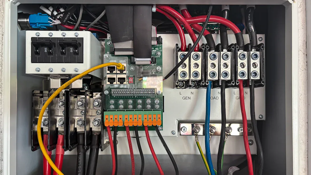
Now you know the parts and types of relays. Let's connect one in a real-world scenario. Understanding a basic relay circuit makes the theory click into place. This section shows you how to wire a relay and choose the right one for your needs.
BASIC WIRING EXAMPLE
Imagine you want to use a small, low-power button to turn on a large, high-power motor. You cannot connect the motor directly to the button. A relay solves this problem. A typical relay wiring diagram shows two separate circuits.
- Control Circuit: You connect your low-power button and its power source (e.g., 5V) to the relay's coil terminals. When you press the button, you energize the electromagnet.
- Load Circuit: You connect your high-power source (e.g., 120V AC) to the Common (COM) terminal. Then, you connect your motor to the Normally Open (NO) terminal.
When you press the button, the relay activates. The internal switch connects COM to NO, and your motor turns on. This is how a relay works to control a heavy load safely. A relay wiring diagram makes these connections easy to follow.
THE ROLE OF A FLYBACK DIODE
When you turn off the power to the coil, its magnetic field collapses. This collapse creates a large, damaging voltage spike in the opposite direction. This is called inductive kick. This spike can destroy the sensitive electronics controlling your relay.
You must protect your circuit with a flyback diode. You connect this diode across the coil terminals in reverse. It provides a safe path for the current to flow when the electromagnet field collapses. This simple component prevents the voltage spike.
Safety First! 💡 A flyback diode is not optional. It is essential for protecting your control components. Look at the difference it makes:
Condition Voltage Spike (approx.) Without Flyback Diode -300 V With Flyback Diode -1.4 V
CHOOSING THE CORRECT RELAY
Selecting the right relay is critical for safety and reliability. You must match the relay to your specific application. Consider these key factors before you make a choice.
First, identify your load type. A motor creates a huge inrush of current when it starts. A capacitive load can draw 20 to 40 times its normal current for a brief moment. A simple resistive load is much easier to handle. The contact material in the relay must be able to handle these surges.
Next, check the datasheet for these specifications:
- Coil Voltage: This must match your control circuit's voltage (e.g., 5V, 12V, 24V).
- Contact Rating (Voltage & Current): The contacts must be rated to handle your load's voltage and current. Always choose a relay with ratings higher than your load requires.
- Contact Configuration: Decide if you need a Normally Open (NO) or Normally Closed (NC) setup for your project.
You now understand how a relay works. These essential relays act as a bridge, letting a small signal safely control a much larger electrical load. This provides critical isolation and remote control. The world of electronics is expanding, with smart relays becoming vital in IoT systems and electric vehicles for advanced monitoring and efficiency.
Now you have the knowledge to use a relay in your own projects. Go ahead and apply what you've learned to build something amazing! 🚀
FAQ
What is the difference between a relay and a switch?
You operate a normal switch by hand. A relay is a switch you control with electricity. You use a small electrical signal to turn a separate, high-power circuit on or off. This allows for remote and automated control.
Can I use a DC relay with AC power?
No, you should not mix them. A DC relay coil on an AC circuit will likely buzz, overheat, and fail quickly. An AC relay on a DC circuit might not work correctly. Always match the relay's coil type to your control circuit's power source.
Why does my relay get hot?
A relay's coil naturally gets warm because it uses power to create the magnetic field. A solid-state relay also generates heat while switching its load.
Heads Up! 🌡️ If a relay becomes too hot to touch, your load current might be too high for its rating.
What does SPDT mean on a relay?
SPDT means Single Pole Double Throw. This type of relay has one common input (Single Pole). It can connect that input to one of two different outputs (Double Throw). It has COM, NO, and NC terminals, letting you switch between two paths.