How a Thyristor Works and Why It Matters in Electronics
A thyristor is a special multi-layer semiconductor device built with four alternating P-N layers. General Electric engineers developed the first commercial version, the silicon controlled rectifier (SCR), in 1956. The most unique trait of a thyristor is its latching ability. A small electrical pulse can trigger the thyristor into its "on" state. It remains on until the main circuit current is cut. This makes the SCR ideal for controlling high-power AC circuits efficiently.
This core function makes the thyristor, or SCR, a fundamental switch in many AC power applications.
Key Takeaways
- A thyristor is a special electronic switch. It turns on with a small signal and stays on until the main power stops.
- Thyristors are good for controlling strong electrical power. They are used in things like light dimmers and motor controls.
- A thyristor has three parts: an anode, a cathode, and a gate. The gate is like a trigger that turns the thyristor on.
- Once a thyristor turns on, it stays on by itself. You must cut the main power to turn it off.
- Thyristors protect electronics from too much power. They can quickly stop harmful electrical surges.
What is a Thyristor?

A thyristor is a semiconductor switch with a unique internal design. Understanding its components helps explain its powerful latching behavior. The most common thyristor is the silicon controlled rectifier (SCR).
The PNPN Structure
A thyristor has a four-layer PNPN structure. Manufacturers create these layers from silicon. They dope intrinsic silicon with specific impurities to form the P-type and N-type layers. This fundamental structure is what gives the thyristor its unique switching characteristics. The SCR is a primary example of this PNPN design.
Anode, Cathode, and Gate
Every thyristor has three terminals that control its operation. These terminals are the Anode, Cathode, and Gate.
- Anode: The terminal where the main current enters the thyristor.
- Cathode: The terminal where the main current exits the thyristor.
- Gate: The control terminal. A small pulse here triggers the thyristor to turn on.
For a common package like the TO-220, the pins have standard roles:
| Pin Number | Terminal Name | Description |
|---|---|---|
| 1 | Cathode | Current flows out of this terminal. |
| 2 | Anode | Current flows into this terminal. |
| 3 | Gate | Controls the SCR conduction. |
An Introduction to Types of Thyristors
There are several types of thyristors, each designed for specific tasks. The SCR, also known as a controlled rectifying diode, is one of the most fundamental types of thyristors. Another important device is the gate turn-off thyristor (GTO), which can be turned off with a gate signal. This makes it useful for high-frequency applications. The different types of thyristors allow engineers to choose the right component for the job. Below is a comparison of two popular types of thyristors.
| Feature | SCR (Silicon Controlled Rectifier) | TRIAC |
|---|---|---|
| Current Flow | Unidirectional (one way) | Bidirectional (both ways) |
| Use Case | DC power control, battery chargers | AC power control, light dimmers |
Exploring the various types of thyristors reveals their versatility in electronics.
Thyristor vs. Transistor
A thyristor and a transistor are both semiconductor switches, but they operate differently. A key difference is how they are controlled. A thyristor latches on with a single pulse, while a transistor needs a continuous signal to stay on. The gate drive circuit for a thyristor is often more complex than for a MOSFET. The SCR is slower than an IGBT but can handle much higher power levels.
💡 Quick Comparison: Thyristor vs. IGBT An Insulated Gate Bipolar Transistor (IGBT) switches faster than an SCR, making it ideal for high-frequency circuits. However, a thyristor excels in very high-power applications where an IGBT might fail.
This makes the thyristor the component of choice for robust, high-power control circuits.
How Do Thyristors Work
Understanding how do thyristors work involves looking at their three distinct modes of operation. A thyristor behaves differently depending on the voltage across its anode and cathode and the signal at its gate. The correct operation of the thyristor is key to its function in a circuit.
Forward Blocking State
In the forward blocking state, the thyristor acts like a locked gate. The anode is positive relative to the cathode, but no signal is applied to the gate terminal. The thyristor remains off and blocks the flow of current. A very small forward leakage current, often just a few microamps, may flow through the SCR, but it is not enough to trigger the device. This state is the default "off" condition for a forward-biased thyristor, awaiting a command to turn on. This specific operation makes the SCR a reliable switch.
Forward Conducting State
The forward conducting state is like an open gate. This operation begins when the thyristor is in its forward blocking state and receives a small positive pulse at its gate.
- The gate pulse triggers the thyristor, causing it to "latch" into the on state.
- The thyristor now conducts current freely from the anode to the cathode.
- It will remain conducting even after the gate pulse is removed.
When an SCR is conducting, there is a small forward voltage drop across it. This voltage drop creates power loss in the form of heat. For a high-power thyristor, this value is quite low.
| Device | Rating (upper) | Forward voltage drop |
|---|---|---|
| Thyristor (SCR) | 1200V/1500A | 1.5V |
Reverse Blocking State
The reverse blocking state is like a one-way street going the wrong way. In this mode, the cathode is positive relative to the anode. The thyristor blocks current flow, similar to a reverse-biased diode. Applying a gate pulse has no effect during this operation. The SCR is designed to block significant reverse voltage, protecting the circuit. If the reverse voltage exceeds the thyristor's breakdown rating, it can be permanently damaged. This blocking capability is essential for any thyristor used in AC circuits.
The Latching Mechanism
The thyristor has a unique ability to "latch" into an on state. This behavior comes from its internal PNPN structure. A simple model helps explain this powerful feature.
The Two-Transistor Analogy
One can visualize a thyristor as two transistors connected together. This model includes a PNP transistor (Q1) and an NPN transistor (Q2). The connection method is key to how the thyristor works.
- The base of the PNP transistor connects to the collector of the NPN transistor.
- The collector of the PNP transistor connects to the base of the NPN transistor.
This configuration creates a special circuit called a regenerative feedback loop. When one transistor starts to conduct, it sends current to the other transistor. The second transistor then conducts more strongly and sends even more current back to the first. This self-reinforcing action drives both transistors to fully turn on, locking the SCR in its conducting state. This process is the foundation of the latching behavior in every thyristor.
From Gate Pulse to Conduction
The latching process begins with a small electrical signal. A positive pulse at the gate terminal acts as the initial trigger. This gate pulse supplies a small base current to the internal NPN transistor (Q2), causing it to start conducting.
Once Q2 conducts, it provides base current to the PNP transistor (Q1). This causes Q1 to turn on. The conducting Q1 then feeds a larger current back into the base of Q2. This positive feedback loop rapidly strengthens, and the anode current flowing through the SCR increases sharply. The device quickly switches from a blocking state to a full conduction state. For the thyristor to latch on, the sum of the internal current gains (α1 + α2) must reach or exceed one.
Latching Current (IL): The anode current must rise above a minimum level, called the latching current, for the thyristor to remain on after the gate trigger pulse is removed. If the current does not reach this level, the SCR will turn off as soon as the gate signal disappears.
Breaking the Latch to Turn Off
Turning a thyristor off is different from turning it on. Removing the gate signal does not work once the SCR is latched. The only way to turn the device off is to break the internal regenerative loop. This happens when the main anode current falls below a specific minimum value.
| Current Type | Definition | Associated Process |
|---|---|---|
| Latching Current (IL) | Minimum anode current needed to latch the SCR on. | Turn-On |
| Holding Current (IH) | Minimum anode current needed to keep the SCR on. | Turn-Off |
The holding current (IH) is the minimum current required to maintain conduction. If the anode current drops below this value, the feedback loop inside the thyristor breaks, and the device returns to its forward blocking state. The latching current is always greater than the holding current.
- An AC source powers the circuit.
- A gate pulse turns the SCR on during the positive half of the AC cycle.
- As the AC cycle ends, the current naturally drops to zero.
- This current drop is below the holding current, so the SCR turns off.
- The following negative half-cycle applies a reverse voltage, keeping the device off.
This natural turn-off makes the SCR an efficient and simple switch for controlling AC power.
Key Thyristor Applications
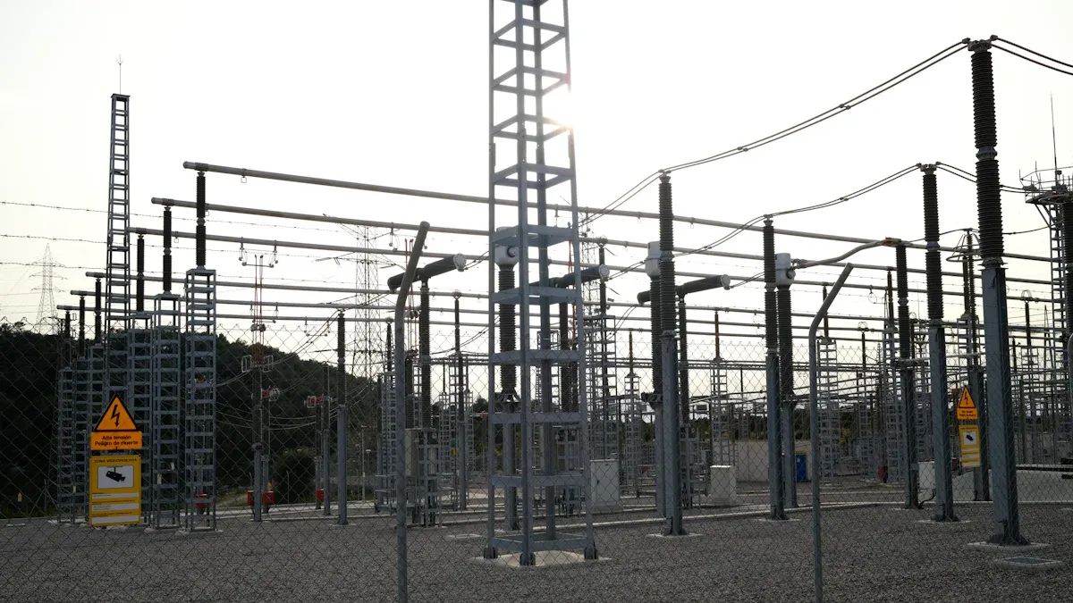
The thyristor's unique latching ability makes it a cornerstone component in high-power electronics. Its efficiency and robustness are ideal for controlling large currents and voltages. This capability allows engineers to use it in a wide range of applications, from household devices to heavy industrial machinery.
Power Control in Dimmers and Motors
A thyristor excels at controlling power delivered to a load. This is most commonly seen in light dimmers and motor speed controllers that run on AC power. The control method, known as phase-angle control, relies on the thyristor's latching feature.
In a simple light dimmer, the device blocks current at the beginning of each AC cycle. A control circuit sends a gate pulse at a specific point in the AC waveform. The thyristor latches on and conducts for the remainder of that half-cycle.
- A pulse early in the AC cycle means the thyristor is on longer, delivering more power and making the light brighter.
- A pulse late in the AC cycle means it is on for a shorter time, delivering less power and dimming the light.
This "fire-and-forget" triggering makes the device very efficient. It only needs a tiny pulse to control a large flow of current for the rest of the AC half-wave.
This same principle applies to motor speed control. Many power tools like drills use a thyristor to manage the speed of their universal motors. These half-wave thyristor circuits effectively control motor speed from a near standstill up to half speed, maintaining relatively constant performance even under load. Full-wave controllers, often using a bidirectional thyristor called a TRIAC, provide even smoother control over the motor's operating range.
For large three-phase induction motors, thyristor-based soft starters are essential. They prevent the immense mechanical and electrical stress caused by sudden startups.
How a Soft Starter Works A microcontroller precisely regulates thyristor firing to smoothly ramp up the voltage supplied to the motor. This gradual start limits damaging inrush currents and reduces starting torque, protecting both the motor and connected machinery from jerks and power surges on the AC line.
| Benefit of Soft Starters | Description |
|---|---|
| Smooth Startup | Eliminates mechanical jerks and electrical stress. |
| Limits Inrush Current | Prevents overheating and tripping circuit breakers. |
| Increased Lifespan | Reduces wear on the motor and connected equipment. |
| Efficiency | Lowers energy consumption during startup. |
Overvoltage and Surge Protection
The fast switching and latching action of a thyristor makes it perfect for protecting sensitive electronics from damaging overvoltage events. A common protection circuit is called a "crowbar."
A crowbar circuit monitors the supply voltage. If the voltage exceeds a safe limit, the circuit triggers a thyristor connected across the power lines. The thyristor immediately latches on, creating a low-resistance path, or a short circuit. This action pulls the voltage down to a safe level, diverting the harmful current away from the protected equipment. The circuit remains latched until a fuse blows or a circuit breaker trips, which also alerts a user to the fault.
The speed of this protection is critical. Thyristor surge protection devices (TSPDs) have some of the fastest response times available.
| Surge Protector Type | Relative Response Time |
|---|---|
| SIDACtor® Thyristors | Fastest |
| TVS Diodes | Faster |
| MOVs | Fast |
| Gas-Discharge Tubes (GDTs) | Slow |
This rapid response is crucial for stopping fast voltage spikes that slower devices might miss, making thyristor circuits a reliable defense for valuable electronics.
High-Power Rectifiers and AC/DC Converters
Rectifiers convert alternating current (AC) to direct current (DC). While simple diodes can do this, they offer no control. Thyristors enable the creation of controlled rectifiers, which can precisely regulate the output DC voltage and current. This is vital in industrial settings that handle massive amounts of power.
Applications like electroplating, anodizing, and high-power welding require a stable and adjustable DC supply. Thyristor-based power supplies deliver this by controlling the exact moment the devices turn on during each AC cycle. This allows for precise regulation of the power delivered to the process.
Engineers build these converters using different configurations.
- Single-Phase Rectifiers: These circuits often use four thyristors in a bridge. During the positive AC half-cycle, two thyristors conduct. During the negative AC half-cycle, the other two are triggered to conduct.
- Three-Phase Rectifiers: For very high-power industrial needs, controlled three-phase bridge rectifiers use six thyristors. A control system pulses the thyristors in a specific sequence to convert the three-phase AC input into a smooth and powerful DC output.
By adjusting the firing angle of the thyristors in these AC to DC converters, operators can manage immense power with high precision, ensuring quality and safety in demanding industrial processes that rely on AC power sources.
A thyristor is a robust semiconductor switch that latches on with a gate pulse. This "fire-and-forget" action makes the thyristor efficient for controlling high-power AC circuits and DC circuits.
This thyristor is vital in everyday AC electronics like dimmers and industrial AC motor controls. It manages AC power effectively. From simple AC devices to complex AC industrial systems, its role in AC power management highlights its importance. It is a key part of AC technology.
FAQ
What is the main difference between a thyristor and a transistor?
A transistor needs a constant signal to stay on. A thyristor, however, latches on with just one pulse. It remains on until the main circuit current is cut. This makes the thyristor ideal for efficient high-power switching.
Why does a thyristor latch on?
The thyristor's four-layer PNPN structure creates an internal positive feedback loop. A gate pulse triggers this loop. The device then holds itself in the "on" state without needing a continuous gate signal. This self-sustaining action is called latching.
How do you turn a thyristor off?
Removing the gate signal does not turn a latched thyristor off. An operator must interrupt the main current flowing from the anode to the cathode. The current must drop below the device's holding current (IH) level to break the latch and turn it off.
What is the most common type of thyristor?
The Silicon Controlled Rectifier (SCR) is the most common and fundamental type of thyristor. It is a unidirectional device, meaning it only allows current to flow in one direction. People often use the terms SCR and thyristor interchangeably in general discussions.