Understanding Rectifiers Half-Wave and Full-Wave Explained
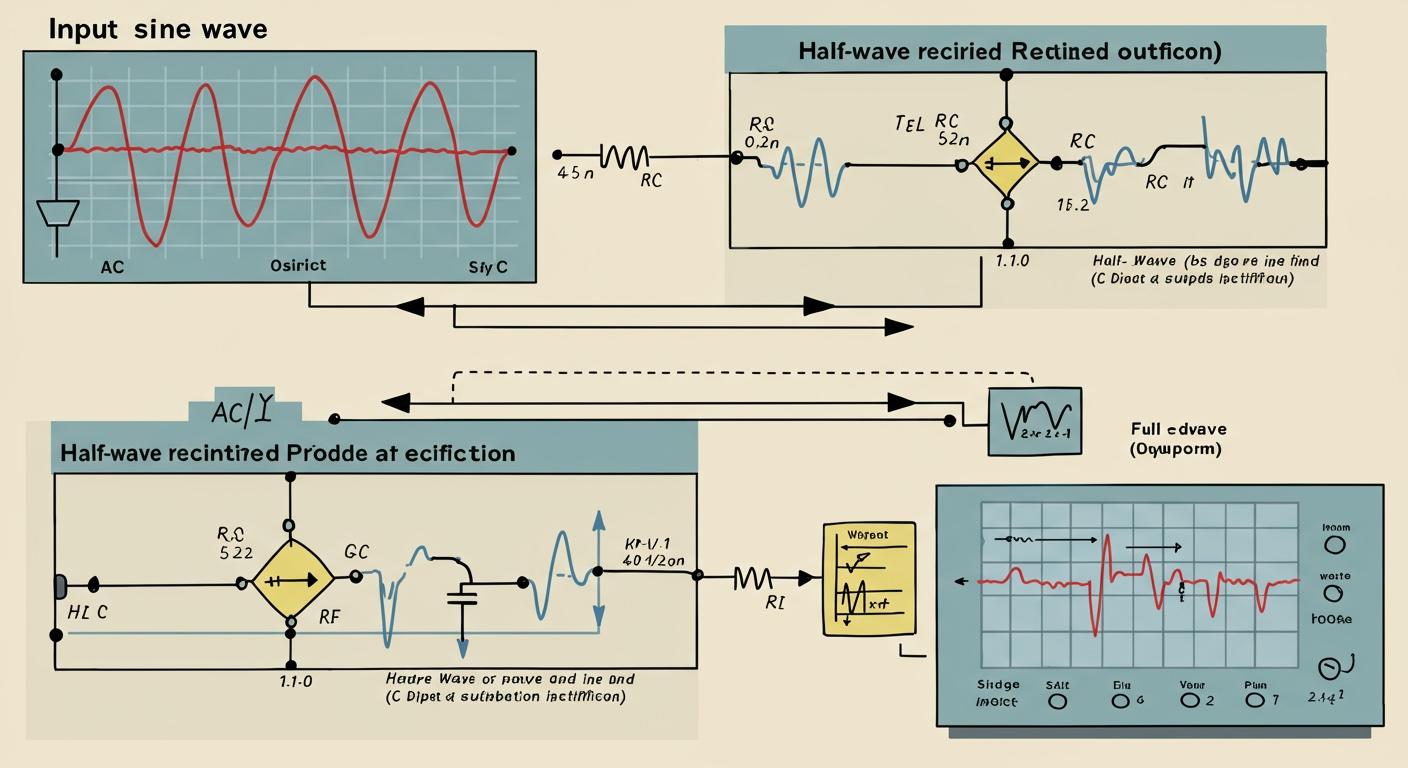
For most electronic projects needing efficient ac to dc conversion, a full-wave rectifier is your best choice. The popular bridge rectifier is a type of full-wave rectifier that delivers stable power.
A
half-wave rectifier, on the other hand, is a simpler and cheaper option. You can use ahalf-wave rectifierfor low-power tasks where output quality is less of a concern. The simplehalf-wave rectifiergets the job done without extra cost.
Understanding the core differences between a full-wave rectifier and its simpler counterpart ensures you can confidently select the right component for your project's specific needs.
Key Takeaways
- Half-wave rectifiers are simple and cheap. They are good for low-power tasks where perfect output is not needed.
- Full-wave rectifiers are better for most projects. They give stable power and are more efficient.
- A bridge rectifier is a common type of full-wave rectifier. It uses four diodes and is very efficient.
- Choose a full-wave rectifier for devices like phone chargers. Choose a half-wave rectifier for simple signal tasks.
- Always pick diodes with the right PIV rating. This protects them from damage.
THE HALF-WAVE RECTIFIER: SIMPLE BUT LIMITED
The half-wave rectifier is the simplest form of AC to DC conversion. Its design is straightforward and uses minimal components, making it an extremely cost-effective choice. However, this simplicity comes with significant performance trade-offs.
HOW IT WORKS: A SINGLE DIODE'S JOB
You can build a basic half-wave rectifier with just one diode. A diode acts like a one-way street for electricity. It allows current to flow in a single direction but blocks it from flowing the other way. When you connect it to an AC source, the diode permits one half of the AC waveform to pass through. It completely blocks the other half. This action converts the alternating current into a pulsating, unidirectional current. The simple half-wave rectifier effectively throws away half of the incoming power to achieve this result.
KEY CHARACTERISTICS: LOW EFFICIENCY, HIGH RIPPLE
The primary drawbacks of a half-wave rectifier are its poor efficiency and rough output.
The maximum theoretical efficiency of a half-wave rectifier is only 40.6%. This means nearly 60% of the input AC power is lost and not converted to useful DC power.
This inefficiency makes the half-wave rectifier unsuitable for most power supply applications. Furthermore, the output voltage is very bumpy. This "bumpiness" is measured by the ripple factor. An unfiltered half-wave rectifier has a very high ripple factor of 1.21, indicating a pulsating DC output that is far from the smooth, stable voltage electronic circuits usually need.
BEST APPLICATIONS: LOW-POWER AND COST-SENSITIVE PROJECTS
So, when would you use a half-wave rectifier? You should choose it for simple, low-power jobs where cost is more important than performance. Its main use is not in power supplies but in signal processing circuits. For example, these rectifiers are common in amplitude modulation (AM) radio circuits for signal demodulation, where they help extract the audio information from the radio wave.
Common uses include:
- AM radio detectors
- Signal peak detection
- Simple pulse-generating circuits
- Basic educational demonstrations
Ultimately, the half-wave rectifier is a valuable circuit for specific, non-critical tasks.
THE FULL-WAVE RECTIFIER: EFFICIENT AND STABLE
When your project demands reliable power, you will want to use a full-wave rectifier. This circuit is the standard for effective ac to dc conversion. It cleverly uses the entire AC waveform, unlike its half-wave counterpart. This process creates a more continuous and stable DC output. You will find the full-wave rectifier in countless devices, from phone chargers and computer power supplies to heavy-duty industrial equipment.
HOW IT WORKS: UTILIZING THE ENTIRE AC WAVE
A full-wave rectifier ensures that no power goes to waste. It captures both the positive and negative halves of the AC cycle. The most common design, the bridge rectifier, uses four diodes to achieve this. Here is how it directs traffic:
- Positive Half-Cycle: During the AC wave's positive phase, two specific diodes turn on. They allow current to flow through the load in one direction. The other two diodes block the current.
- Negative Half-Cycle: When the AC wave switches to its negative phase, the roles reverse. The other pair of diodes turns on, while the first pair switches off.
- Result: This clever switching action steers the current from both halves of the AC cycle. It makes the current always flow through the load in the same direction, producing a pulsating DC output.
CENTER-TAP VS. BRIDGE CONFIGURATIONS
You can build a full-wave rectifier in two primary ways: with a center-tapped transformer or as a bridge rectifier. The bridge configuration is far more common today. The main difference lies in the transformer and the number of diodes you need.
| Characteristic | Bridge Rectifier | Center-Tapped Rectifier |
|---|---|---|
| Diodes Needed | 4 | 2 |
| Transformer Type | Standard, simpler | Special, center-tapped |
| Transformer Size | Smaller and less complex | Larger and more complex |
| Overall Cost | Generally lower | Generally higher |
KEY CHARACTERISTICS: HIGH EFFICIENCY, LOW RIPPLE
The biggest advantage of a full-wave rectifier is its superior performance. It is much better at converting AC power into useful DC power.
The maximum theoretical efficiency of a full-wave rectifier is 81.2%. This is double the efficiency of a half-wave circuit, meaning far less power is wasted.
This higher performance makes it the perfect foundation for almost any DC power supply. Additionally, its output has a much lower ripple. The pulses are closer together, making the DC voltage smoother and much easier to filter into a stable, clean supply for your sensitive electronic components.
HEAD-TO-HEAD: FULL-WAVE VS. HALF-WAVE
Choosing between a half-wave and full-wave rectifier comes down to a simple trade-off: cost versus performance. Let's break down the key differences so you can see exactly what you gain or lose with each choice. This direct comparison will help you decide which circuit is the right tool for your job.
POWER AND EFFICIENCY: DELIVERING MORE JUICE
The most significant difference is how each circuit uses the incoming AC power. A half-wave rectifier simply throws away half of the power. This results in a maximum theoretical efficiency of only 40.6%. You lose nearly 60% of the potential energy as wasted heat.
In contrast, you get much higher efficiency from a full-wave rectifier. It uses both halves of the AC cycle, achieving a maximum theoretical efficiency of 81.2%. This means you convert twice as much of the input power into useful DC power for your project. For any application that needs to deliver consistent power, the choice is clear.
OUTPUT RIPPLE: THE SMOOTHNESS FACTOR
Ripple refers to the leftover AC "bumpiness" in your DC output. A smoother output has less ripple and is better for sensitive electronics. Here, the full-wave rectifier has a major structural advantage.
Pro Tip 💡: A
half-wave rectifierproduces ripple at the same frequency as the AC line (e.g., 60 Hz in the US). Afull-wave rectifierproduces ripple at twice the line frequency (120 Hz).
This higher ripple frequency is much easier to smooth out. You can use a smaller, cheaper filter capacitor to achieve the same level of smoothness you would get from a larger, more expensive capacitor on a half-wave circuit. This saves you both space and money on your board.
THE BRIDGE RECTIFIER ADVANTAGE
The bridge rectifier is the most popular type of full-wave circuit for a reason. A significant advantage of this design is that it does not require a special center-tapped transformer. This simplifies your overall design and reduces the cost and size of your power supply. While a center-tapped design also provides full-wave rectification, the need for a more complex and expensive transformer makes it less common.
The difference also comes down to the number of diodes you need.
| Rectifier Type | Diodes Needed | Transformer Type |
|---|---|---|
| Half-Wave | 1 | Standard |
| Full-Wave (Center-Tap) | 2 | Center-Tapped |
| Full-Wave (Bridge) | 4 | Standard |
CIRCUIT COST AND COMPLEXITY
At first glance, the half-wave rectifier is the winner for simplicity. It uses only one diode and is the cheapest circuit to build. You cannot make a rectifier any simpler.
However, the bridge rectifier offers a much better value proposition for most projects. While it requires four diodes, it eliminates the need for a costly center-tapped transformer. Electronic component experts favor this design because it provides superior full-wave performance without complex parts. The small additional cost for three extra diodes is a tiny price to pay for doubling your efficiency and getting a much smoother output that is easier to filter. For almost any power supply, this makes the bridge design the smarter, more practical choice.
CHOOSING THE RIGHT RECTIFIER FOR YOUR PROJECT
Now you understand the differences between the two rectifier types. The final step is to match the right design to your project's needs. Your choice will depend on your requirements for power, stability, and cost.
WHEN TO CHOOSE A FULL-WAVE DESIGN
You should select a full-wave rectifier when your project needs stable and efficient DC power. This design is the standard for most power supply applications because it provides a smoother output that is easier to filter. Choose this option for any sensitive electronics.
Common projects that require a full-wave design include:
- DC Power Supplies: For lab-bench equipment, computers, and industrial controls.
- Battery Charging Circuits: For safely charging smartphones, laptops, and other portable devices.
- LED Driver Circuits: To provide a steady current and prevent flickering in LED lights.
- Uninterruptible Power Supplies (UPS): Essential for critical systems in hospitals or data centers.
WHEN A HALF-WAVE DESIGN IS SUFFICIENT
A half-wave rectifier is a good choice for simple, low-power tasks where performance is not critical. You can use it when cost and simplicity are your main priorities. Its high ripple and low efficiency make it unsuitable for powering most electronics directly.
A half-wave rectifier works well in these situations:
- Signal Demodulation: Used in AM radio circuits to extract audio from a radio wave.
- Pulse Generation: For simple circuits that trigger switches or blink an LED.
- Basic Charging: For small, non-regulated charging systems, like those in a riding mower, where output is only a few amps.
THE ROLE OF TRANSFORMERS AND CAPACITORS
Your rectifier circuit is not complete with just diodes. You also need to consider transformers and capacitors. A transformer steps the AC voltage up or down, while a filter capacitor smooths the pulsating DC output.
A capacitor acts like a small reservoir. It charges to the peak voltage and then slowly releases that energy, which raises the average DC voltage and smooths out the ripple. A larger capacitor provides a smoother output.
When selecting diodes, you must check their Peak Inverse Voltage (PIV) rating.
- What is PIV? It is the maximum reverse voltage a diode can handle without breaking.
- Why does it matter? If the circuit's voltage exceeds the diode's PIV, the diode can be permanently damaged. You should always choose diodes with a PIV rating safely above your circuit's expected maximum voltage.
Your choice between rectifiers involves a clear trade-off. A half-wave rectifier offers unmatched simplicity for low-demand jobs. A full-wave rectifier delivers the efficiency and stability required for most modern power applications.
Your project's specific needs for power, performance, and cost will always guide your decision. 💡
Ultimately, the full-wave bridge rectifier is the go-to standard for reliable DC power. Understanding both designs, however, is a valuable skill for any electronics enthusiast. You can now confidently select the right component for your next build.
FAQ
Why does a bridge rectifier need four diodes?
You use four diodes to create two paths for the current. One pair of diodes directs the positive half of the AC wave. The other pair directs the negative half. This clever setup ensures your load receives power from the entire AC cycle, making it very efficient.
What is PIV and why does it matter?
PIV stands for Peak Inverse Voltage. It is the maximum voltage a diode can block when current tries to flow backward. You must choose diodes with a PIV rating safely above your circuit's voltage to prevent them from being destroyed.
Can I use a half-wave rectifier to charge my phone?
No, you should avoid this. A phone requires a very stable and clean power source. A half-wave rectifier provides inefficient, bumpy power that can damage your phone's sensitive electronics. Always use a full-wave rectifier for modern battery chargers. 🔋
What does a filter capacitor do?
A filter capacitor's job is to smooth out the pulsating DC output from the rectifier. It works by:
- Storing energy when the voltage is at its peak.
- Releasing that energy when the voltage drops.
This action fills in the "gaps" between pulses, creating a much smoother DC voltage.