The 2025 Guide to AND OR and XOR Logic Gates
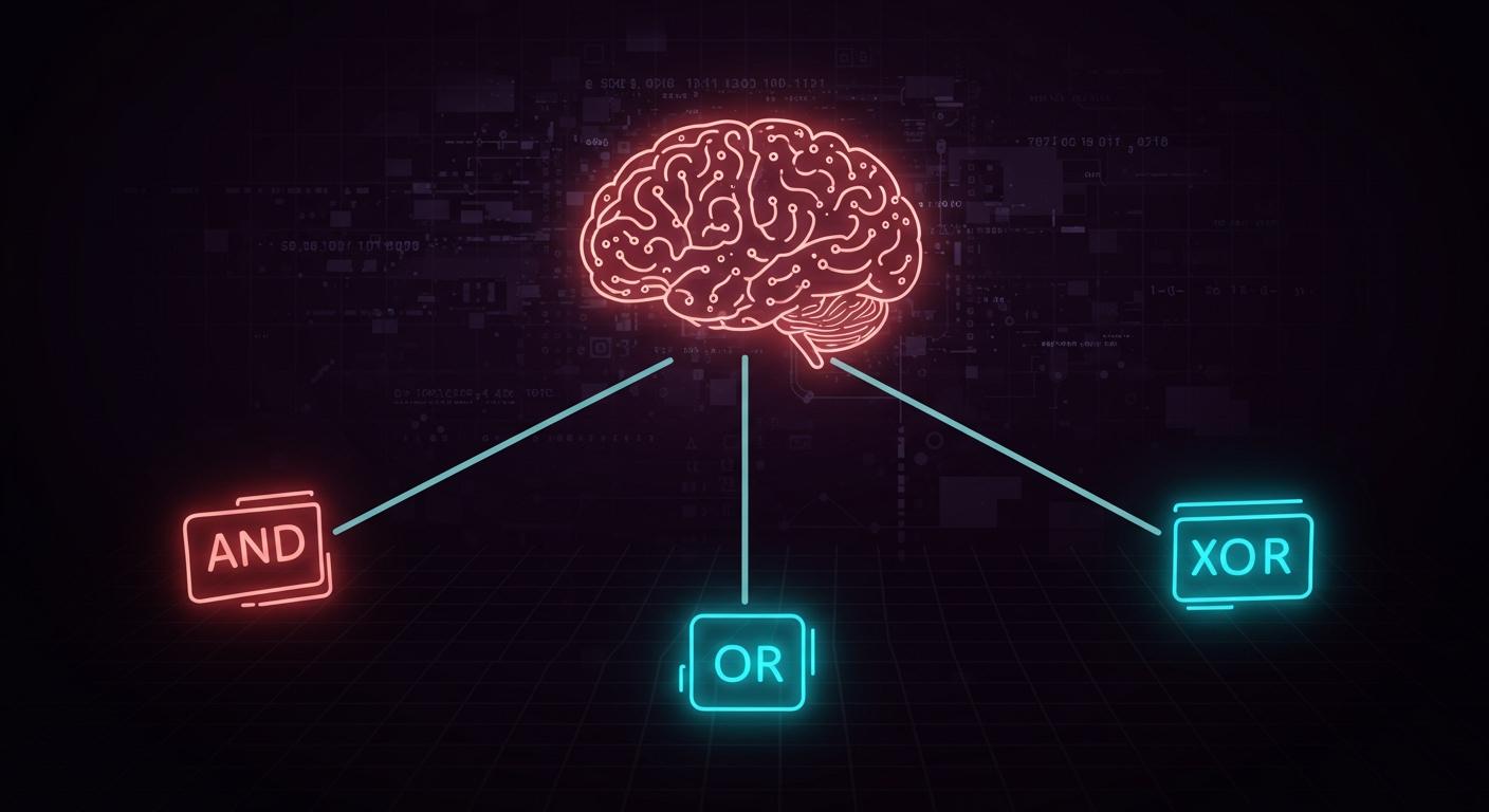
The AND, OR, and XOR gates are the fundamental decision-makers in all digital logic. 🧠 Ever wondered how a computer makes billions of choices per second? The answer lies in simple logic gates. Each gate performs a tiny logic function. These logic gates combine to form complex circuits, and the xor and or gate are two key types. Modern chips pack billions of these components.
A Look at 2025-Era Processor Scale
GPU Model Transistor Count Nvidia Blackwell B100 128 billion
Key Takeaways
- Logic gates are the basic parts of all digital devices. They make decisions based on simple rules.
- The AND gate needs all inputs to be true. The OR gate needs at least one input to be true. The XOR gate needs inputs to be different.
- Truth tables show how each logic gate works. They list all possible inputs and their outputs.
- Logic gates are very important for computers. They help with processors, AI, and keeping data safe.
- The XOR gate is different from the OR gate. The XOR gate outputs false when both inputs are true. The OR gate outputs true in that case.
Understanding Logic Gates
The Brain of Digital Circuits
Logic gates are the microscopic brains inside every digital device. They act as the fundamental building blocks in all digital electronics. Each gate performs a single, simple logic operation. Thousands or millions of these gates connect to form a complex circuit. This circuit can then perform advanced tasks, like adding numbers or storing data. The entire field of digital electronics relies on the predictable behavior of these tiny components.
Inputs and Outputs
Every logic gate processes electrical signals through inputs to produce a single output signal. These signals represent binary data: a '1' (TRUE) or a '0' (FALSE). In a physical circuit, these binary states correspond to specific voltage levels. A high voltage represents a '1', while a low voltage represents a '0'. This system allows the gate to make a decision based on the logic it receives.
Note on CMOS Voltage Levels In common CMOS technology, the logic levels are defined by a percentage of the supply voltage (VDD). This ensures the gate operates reliably.
Technology Logic 0 Voltage Range Logic 1 Voltage Range CMOS 0 V to 30% VDD 70% VDD to VDD
The Role of a Truth Table
A truth table is a chart that defines a gate's function. It is a core tool for understanding boolean functions. The table lists every possible combination of inputs and shows the resulting output for each one. This map makes the behavior of any gate completely predictable. A truth table is essential for designing and testing digital logic systems. It validates the output from different input combinations for all basic logic gates. Engineers use a truth table to prove that their boolean functions will work as intended.
The AND Gate
The AND gate is a fundamental component in digital logic. It follows a strict "all-or-nothing" rule. This gate requires every input to be TRUE (1) to produce a TRUE (1) output. If any input is FALSE (0), the output will also be FALSE (0). The and gate acts like a security checkpoint where everyone in a group must have a valid pass. Many digital systems use these gates to enforce strict conditions.
AND Function
The primary function of an and gate is to perform logical multiplication. Think of it as a decision-maker that only says "yes" when all conditions are met. This makes the and gate essential for processes requiring multiple confirmations.
2025 Example: Multi-Factor Authentication (MFA) 🔐
Modern security relies heavily on the AND logic. When you log into a secure account, the system checks for your password AND a code from your phone.
- Input A: Password is correct (1)
- Input B: Phone token is correct (1)
- Output: Access Granted (1)
The system uses an and gate concept. Access is denied if either the password or the token is incorrect. This simple logic dramatically increases security. Other gates could not provide this level of strict validation.
The AND Gate Symbol
Engineers use a standard symbol to represent an and gate in circuit diagrams. The shape is a capital letter 'D'. The inputs enter the flat side, and the single output leaves from the curved side.
  Input A -----|
               | AND
  Input B -----|
               |----- Output
This symbol provides a universal language for designers creating complex boolean functions.
AND Truth Table
A truth table clearly defines the behavior of an and gate. It lists all possible input combinations and the resulting output for each. The truth table for a 2-input and gate is a core part of understanding its boolean functions.
| Input A | Input B | Output |
|---|---|---|
| 0 | 0 | 0 |
| 0 | 1 | 0 |
| 1 | 0 | 0 |
| 1 | 1 | 1 |
This table proves the gate's rule. Only one combination (1 and 1) results in a TRUE output.
The OR Gate
The OR gate offers more flexibility than the AND gate. It follows an "any-is-enough" rule. This logic gate produces a TRUE (1) output if at least one of its inputs is TRUE (1). The output is only FALSE (0) when all inputs are FALSE (0). This behavior makes the or gate ideal for situations where multiple conditions can trigger a single outcome. Many systems use these gates for monitoring and alert functions.
OR Function
The main purpose of an or gate is to perform logical addition. It acts as a detector, signaling "yes" if any of its conditions are met. This makes the or gate a key component in systems that need to respond to various triggers. Its role in boolean functions is to create inclusive conditions.
2025 Example: Smart Home Alarm System 🚨
A modern smart home alarm demonstrates the or gate logic perfectly. The system can use multiple sensors. The alarm activates if a door sensor OR a motion sensor is triggered.
- Input A: Door sensor is triggered (1)
- Input B: Motion sensor is not triggered (0)
- Output: Alarm sounds (1)
In this setup, the alarm sounds if either sensor detects an event. The system does not require both to be active. This simple or gate logic provides comprehensive security coverage. Other logic gates could not achieve this flexible monitoring.
The OR Gate Symbol
Circuit diagrams represent an or gate with a distinct, curved symbol. The inputs enter the concave side, and the single output leaves from the pointed convex side. This shape helps engineers quickly identify the gate's function.
  Input A -----|
               | OR
  Input B -----/
               |----- Output
This universal symbol is essential for designing complex circuits with clear boolean functions.
OR Truth Table
The truth table for an or gate clearly shows its behavior. It lists every input combination and the corresponding output. This table confirms that the gate will output a 1 if any input is a 1.
| Input A | Input B | Output |
|---|---|---|
| 0 | 0 | 0 |
| 0 | 1 | 1 |
| 1 | 0 | 1 |
| 1 | 1 | 1 |
This truth table is a fundamental tool for verifying the logic of a circuit.
The XOR Gate
The XOR gate, or exclusive-or gate, is a digital logic gate that acts as a difference detector. It follows a strict "one-or-the-other, but not both" rule. This gate produces a TRUE (1) output only when its inputs are different. If both inputs are the same (either both 0 or both 1), the output is FALSE (0). This unique behavior makes the exclusive-or gate essential for tasks involving comparison, data checking, and basic cryptography.
XOR Function
The primary function of an xor gate is to identify inequality. It is a crucial component in arithmetic logic units (ALUs) and error-detection circuits. Its ability to compare two bits and output a 1 if they are not identical is fundamental to many digital operations.
2025 Example: Data Integrity & Encryption 🛡️
The exclusive-or gate is critical for ensuring data is transmitted correctly and securely.
- Parity Bit Calculation: Systems use the xor gate to check for errors in data. A parity checker uses xor gates to see if the total number of '1's in a data stream is even or odd. The xor operation naturally calculates this, helping to detect if a bit was flipped during transmission.
- Simple Encryption: The xor function provides a simple way to encrypt data. A message (plaintext) is combined with a secret key using an xor operation. Applying the same key a second time reverses the process, revealing the original message.
Technical Note: Transistor Construction An exclusive-or gate is often a compound gate built from other, simpler gates. A popular and efficient design uses four
nandgates to create one xor gate. Thisnandgatestructure involves a firstnandgateand a secondnandgateprocessing the inputs, with a thirdnandgateand fourthnandgatecombining their results. Thisnandnandnandnandnandnandnandnandbased construction is a classic example. In modern CMOS technology, an xor gate can be built with as few as 8 to 16 transistors. The inverse of this gate is the exclusive-nor gate, which outputs 1 when inputs are the same. The exclusive-nor gate is also fundamental. The exclusive-nor gate and exclusive-or gate are complementary.
The XOR Gate Symbol
The symbol for an xor gate resembles the OR gate symbol but with an additional curved line on the input side. This extra line signifies its "exclusive" nature.
  Input A -----|
               )\
  Input B -----| )---- Output
               )/
This distinct symbol allows engineers to easily identify the gate in complex circuit diagrams.
XOR Truth Table
The xor truth table clearly demonstrates its unique logic. It lists all input combinations and shows that the output is 1 only when the inputs differ. This truth table is the definitive map of the gate's behavior.
| Input A | Input B | Output |
|---|---|---|
| 0 | 0 | 0 |
| 0 | 1 | 1 |
| 1 | 0 | 1 |
| 1 | 1 | 0 |
This table confirms the function of the exclusive-or gate as a powerful tool for digital comparison.
The NOT Gate Inverter
The NOT gate, also known as an inverter, is the simplest of all logic gates. It has only one input and one output. Its job is to perform logical negation. This means the NOT gate inverts or complements its input signal. If the input is TRUE (1), the output becomes FALSE (0). If the input is FALSE (0), the output becomes TRUE (1). This fundamental gate is a critical building block in digital electronics, often working with other gates to create complex logic. The NOT gate is essential for many operations.
NOT Function
The primary function of a NOT gate is to reverse the logic level of its input. The output from a NOT gate is always the opposite of its input. This makes the NOT gate a powerful tool for signal inversion. Many digital circuits use this simple gate to control other components or to construct more complex logic gates like NAND and NOR gates. The NOT gate is not a decision-maker like other gates; it is a signal flipper.
2025 Example: Building Blocks of Memory 💾
The humble NOT gate is fundamental to Static RAM (SRAM), the high-speed memory in modern CPUs.
- Two NOT gates can be connected in a loop, creating a "cross-coupled inverter" pair.
- This simple circuit forms a basic memory cell that can store a single bit of data (a 1 or a 0).
- The two inverters reinforce each other's state, holding the value stable until a stronger signal overwrites it. This shows how the most basic gate builds the foundation for complex memory systems.
The NOT Gate Symbol
Engineers represent the NOT gate in circuit diagrams with a simple symbol. It is a triangle pointing toward the output, with a small circle at its tip. The circle, called a "bubble," signifies the inversion.
Input -----|>o----- Output
This symbol clearly shows that the input signal will be inverted by the NOT gate.
NOT Truth Table
The truth table for a NOT gate is the shortest of all logic gates. It has only one input, so there are only two possible scenarios. This table perfectly defines the behavior of the NOT gate.
| Input | Output |
|---|---|
| 0 | 1 |
| 1 | 0 |
This table confirms that the output is always not the same as the input. The NOT gate is a simple yet vital component.
Comparing the Logic Gates
Understanding the individual function of each logic gate is the first step. The next step is comparing them directly. This comparison reveals their unique roles in digital logic. Each gate processes binary inputs differently to produce a specific output. Seeing their behaviors side-by-side clarifies their distinct purposes. The full and, or and not set of gates provides the complete foundation for all digital computation.
Master Truth Table
A master truth table is an excellent tool for comparison. It places the outputs of multiple logic gates next to each other for the same set of inputs. This format provides a clear, at-a-glance reference for their different behaviors. The table below shows the outputs for AND, OR, and XOR gates given two inputs. It also includes the NOT gate's output for Input A to show inversion. This truth table is a map of digital logic.
This single truth table summarizes the core rules. The AND gate needs all inputs to be 1. The OR gate needs at least one input to be 1. The XOR gate needs the inputs to be different.
Visualizing with Venn Diagrams
Venn diagrams create a visual picture of how logic gates work. Each input is a circle. The shaded area shows which input combination results in a TRUE (1) output. These diagrams help make the abstract logic of gates more concrete.
- AND Gate: The diagram for an AND gate shows only the overlapping area between the two circles shaded. This visualizes the rule that both Input A and Input B must be TRUE.
- OR Gate: The diagram for an OR gate shows both circles and their overlapping area shaded. This represents the rule that Input A or Input B (or both) can be TRUE.
- XOR Gate: The diagram for an XOR gate is special. It shows only the parts of the circles that do not overlap. The overlapping section is left unshaded. This perfectly illustrates the "one or the other, but not both" logic.
Comparing the XOR and OR Gate
The xor and or gate are often confused, but they have one critical difference. Both gates produce a TRUE (1) output when only one of their inputs is TRUE. Their behavior diverges when both inputs are TRUE. This single difference defines their separate roles in digital systems. The full and, or and not set of gates are all distinct.
The Key Difference: The "Both TRUE" Case
The OR gate is inclusive. It asks, "Is at least one input true?" The XOR gate is exclusive. It asks, "Is exactly one input true?"
A simple table highlights this specific case:
| Input A | Input B | OR Output | XOR Output |
|---|---|---|---|
| 1 | 1 | 1 | 0 |
The standard OR gate produces a '1' when both inputs are '1'. The XOR gate, however, generates a '0' in this exact scenario. A good way to remember the XOR gate's function is 'one or the other but not both'. This exclusive logic makes the XOR gate a powerful tool for tasks like error checking and cryptography, while the OR gate is better for general-purpose triggers. The xor and or gate each have a unique and important job. This specific gate behavior is fundamental to computer logic.
Applications for Logic Gates in 2025
Simple logic gates are the atoms of the digital universe. They combine in vast numbers to power the most advanced technologies of 2025. Their basic rules of logic enable everything from complex calculations in a processor to the foundations of quantum computing. Understanding their applications reveals how simple decisions build our complex digital world.
Advanced Processors and GPUs
Every modern processor and GPU is a city of billions of transistors forming logic gates. These gates are the workers that perform every calculation. The core of a CPU, the Arithmetic Logic Unit (ALU), is built directly from these components.
- An ALU is constructed from basic logic gates like AND, OR, and XOR.
- It uses these gates in parallel to handle large numbers. For example, a 32-bit operation uses 32 AND gates working at once.
- Special circuits called multiplexers, also built from logic gates, select which operation the ALU should perform.
A fundamental circuit inside the ALU is the full adder, which adds binary numbers. Engineers can build a full adder circuit in several ways. One common method involves combining smaller components.
- A full adder can be made from two half adders and an OR gate.
- The first half adder takes two bits (A and B) and produces a sum and a carry.
- The second half adder takes that sum and a third bit (the carry-in).
- An OR gate then combines the carry signals from both half adders to produce the final carry-out.
This design shows how a complex operation like addition breaks down into simple logic. The processor's control unit also uses logic to manage the flow of instructions through a pipeline. This pipeline allows the CPU to work on multiple instructions at once, with each stage using logic gates to do its part. This arrangement makes modern processors incredibly fast and efficient.
Operations in Artificial Intelligence
Artificial Intelligence and machine learning models require immense computational power. This power comes from Graphics Processing Units (GPUs) packed with thousands of processing cores. At the heart of each core, logic gates do the heavy lifting.
The training of an AI model involves billions of simple mathematical operations, primarily matrix multiplication and addition. The ALUs inside the GPU perform these calculations at incredible speeds. Each calculation is a direct result of the logic gates executing their functions. The speed of AI depends on the efficiency of the underlying gates. The ability to build any logic function from NAND or NOR gates, known as universal logic gates, is key to designing these dense chips. These universal logic gates provide the flexibility needed for complex processor design.
Modern Cryptography
Cryptography protects our digital information, and logic gates are central to its methods. The XOR gate is especially important for encryption. Symmetric key algorithms use the XOR function to combine plaintext data with a secret key.
The XOR operation transforms the data into unreadable ciphertext. Applying the same key with another XOR operation reverses the process, restoring the original plaintext. This simple logic provides a fast and secure way to encrypt and decrypt information.
Cryptographic hash functions like SHA-256 also rely on logic gates. These algorithms compress large amounts of data into a small, fixed-size hash.
"These utils are basically logic gates or boolean functions, and we will use them bit wise."
In SHA-256, these boolean functions work with adders and other operations in a loop to mix and digest data. This process, driven by the predictable behavior of each gate, creates a secure digital fingerprint for the data. The design of these systems often relies on universal logic gates. These universal logic gates can create any needed function. The concept of universal logic gates is fundamental. In fact, universal logic gates are a cornerstone of digital design.
Role in Quantum Gate Computing
Quantum computing represents a new frontier, but it shares a conceptual foundation with classical computing. Classical logic gates provide the model for quantum gates, which manipulate quantum bits (qubits). The principles of using logic gates in circuits are extended into the quantum realm.
- The quantum CNOT gate acts like a reversible classical XOR gate. It is a fundamental building block for quantum circuits.
- The Toffoli gate is a three-qubit gate that acts as a controlled-controlled-NOT. It flips a target qubit only if two control qubits are both 1.
- This Toffoli gate is universal for classical reversible computation. It can be built from CNOT gates and other simple quantum gates. This shows how quantum systems can perform classical logic functions like AND.
This connection demonstrates how the simple ideas of AND, OR, and XOR logic are evolving. The principles behind universal logic gates in classical computing inspire the search for universal quantum gates. These universal logic gates are essential for building a fault-tolerant quantum computer. The theory of universal logic gates helps bridge the two fields. The power of universal logic gates is a recurring theme. The study of universal logic gates continues to be important.
The AND gate sets strict rules, the OR gate offers flexible options, and the XOR gate finds differences. These simple logic gates are the foundation of all digital technology. Their core logic inspires future computing paradigms.
A Look to the Future: Biological Computing
- DNA computing uses logic gates like AND, OR, and XOR.
- Protein-based logic also creates a similar gate.
Understanding the xor and or gate is vital. A grasp of the xor and or gate and their logic is more relevant than ever for anyone in coding or AI engineering.
FAQ
What is the main difference between an OR gate and an XOR gate?
The OR and XOR gates differ in one key scenario. The OR gate outputs a 1 when both inputs are 1. The XOR gate outputs a 0 in that same case.
Remember:
- OR is inclusive (one or both).
- XOR is exclusive (one but not both).
Why do engineers call NAND and NOR gates "universal gates"?
Engineers call them universal gates because they can create any other logic function. Combinations of NAND gates can build AND, OR, and NOT gates. This makes them powerful building blocks for designing complex digital circuits.
How many transistors does a logic gate use? ⚙️
The transistor count varies. A simple NOT gate uses two transistors. More complex gates use more. The specific design and technology determine the final count.
| Gate Type | Typical Transistor Count (CMOS) |
|---|---|
| NOT | 2 |
| NAND | 4 |
| XOR | 8 to 16 |
Can a logic gate have more than two inputs?
Yes, many logic gates can have more than two inputs. AND and OR gates often have multiple inputs. The gate's basic rule still applies to all of them.
// A 3-input AND gate
Input A --|
Input B --| AND |-- Output (1 only if A, B, AND C are 1)
Input C --|