What makes differential op amps vital for modern signal processing

Differential op amp technology stands at the heart of modern electronics. Engineers use these devices to amplify signals with high accuracy and strong noise rejection. Modern electronics rely on differential op amps, especially in precision electronics, to maintain clear data. Medical devices, sensor systems, and instrumentation all depend on modern electronics powered by differential op amps. Modern electronics benefit from their ability to deliver reliable results and support advanced applications.
Key Takeaways
- Differential op amps amplify only the difference between two input signals, which helps reject noise and interference for clearer, more accurate results.
- High common-mode rejection ratio (CMRR) allows differential op amps to block unwanted noise from power lines and electromagnetic interference, preserving signal quality.
- The symmetrical input stage and high input impedance prevent signal loss and improve precision, making differential op amps ideal for weak or noisy signals.
- Careful resistor matching, buffering, and circuit layout are essential to maintain high CMRR and stable gain, ensuring reliable amplifier performance.
- Differential op amps are vital in many fields like medical devices, sensor systems, and industrial controls, where accurate and noise-free signal processing is critical.
Differential Op Amp Basics
Differential Amplifier Function
A differential amplifier forms the core of every differential op amp. This circuit amplifies the voltage difference between two inputs. It rejects any voltage that appears the same on both inputs. Engineers call this ability "common-mode rejection." The output voltage depends on the difference between the two input voltages. The relationship follows the formula:
V_out = A(V_in^+ - V_in^-),
where A stands for the gain of the amplifier. This means the operational amplifier only responds to the difference, not to signals that both inputs share. This property makes the differential amplifier ideal for handling differential signals in noisy environments.
The differential pair inside the operational amplifier uses a special design. It gets its bias from the emitter side. Negative feedback helps stabilize the operation. A constant current source, sometimes called a "long tail," keeps the current steady. This design ensures the amplifier rejects common-mode signals and only amplifies the voltage difference. The output comes from the difference in collector currents, which match the difference in input voltages. This approach allows the operational amplifier to achieve precise differential amplification.
Op-Amp Input Stage
The input stage of a differential op amp uses a symmetrical design. This symmetry improves both precision and stability. Engineers use matched resistor pairs and careful layout to keep the circuit balanced. The table below shows how different aspects of the symmetrical input stage help the operational amplifier perform better:
| Aspect | Explanation | Contribution to Precision and Stability |
|---|---|---|
| Symmetrical resistor matching | Using equal resistor pairs ensures the amplifier only amplifies the difference signal | Enables high common-mode rejection ratio (CMRR), reducing noise and interference |
| Common-mode rejection (CMRR) | The circuit rejects signals common to both inputs | Keeps output clean and accurate by ignoring unwanted signals |
| Use of high-precision resistors | Resistors matched within tight tolerances and laser trimming in ICs | Enhances stability and accuracy by maintaining resistor balance |
| Temperature considerations | Selecting resistors with low temperature coefficients or arranging them to minimize thermal effects | Maintains stable performance despite temperature changes |
| Symmetrical design benefits | Simplifies gain calculation and maintains linearity | Supports precise amplification and stable output |
A differential op amp also features high input impedance. This means it draws very little current from the signal source. In precision operational amplifiers, the input impedance at the noninverting terminal often reaches several kilo-ohms. The inverting input impedance can be about one-third of the noninverting side, depending on the internal resistor network. Some operational amplifiers used in audio or measurement systems have differential input impedances around 400 ohms and common-mode input impedances near 600 ohms. High input impedance prevents the amplifier from loading the signal source, which helps maintain signal integrity.
The symmetrical input stage and high input impedance work together. They allow the operational amplifier to deliver accurate differential amplification, even when the input signals are weak or noisy. These features make differential op amps essential for modern signal processing tasks.
Common-Mode Rejection Ratio (CMRR)
Noise Suppression
The differential amplifier plays a key role in reducing unwanted signals. Engineers use the common-mode rejection ratio, or CMRR, to measure how well a differential amplifier can block common-mode noise. CMRR is the ratio of the amplifier's ability to amplify the difference between two input signals to its ability to amplify signals that are the same on both inputs. The formula for CMRR is:
CMRR = 20 log10(Ad / |Acm|)
where Ad is the differential gain and Acm is the common-mode gain. A high CMRR means the differential amplifier can reject most common-mode noise, which is important for accuracy in signal processing.
In real-world circuits, common-mode noise often comes from sources like power lines or electromagnetic interference. These unwanted signals appear equally on both inputs of the differential amplifier. The amplifier's design, including precise resistor matching and symmetrical layout, helps it attenuate common-mode noise. For example, a typical operational amplifier such as the TL072 has a minimum CMRR of about 75 dB. This means it can reduce common-mode noise by a factor of over 3,000 compared to the desired signal. High-performance differential amplifiers, especially those used in medical devices or audio systems, can achieve CMRR values above 100 dB. This level of common-mode rejection is critical for maintaining accuracy in sensitive applications.
Tip: Engineers often choose amplifiers with high CMRR for environments with lots of electrical noise. This choice helps keep the output signal clean and reliable.
Signal Integrity
Signal integrity means the signal stays true to its original form as it moves through a circuit. The differential amplifier uses its high CMRR to protect signal integrity, especially in places with strong electromagnetic interference. When common-mode noise enters both inputs, the differential amplifier rejects it, allowing only the difference between the signals to pass through. This process keeps the output accurate and stable.
- High CMRR is essential for rejecting common-mode noise caused by electromagnetic interference and ground potential differences. This feature preserves the fidelity of the desired differential signal.
- Differential amplifiers with high CMRR are important in communication systems, power electronics, and sensor interfaces. These systems often face external noise that can lower signal quality.
- Circuit symmetry, precision components, and careful layout all help improve CMRR. These design choices boost the amplifier's ability to maintain accuracy.
- CMRR can decrease at higher frequencies, so engineers must consider frequency effects in environments with lots of electromagnetic interference.
- Effective CMRR allows for clearer signal transmission and reception. This clarity is vital for high data rates and fewer errors in digital communication systems.
Differential Op Amp Features
High Input Impedance
A differential amplifier in an operational circuit often features a high input impedance. This design comes from the emitter-coupled pair at the input stage, which can reach values in the megaohm range. For example, a classic 741 op-amp shows about 2 MΩ input impedance. High input impedance means the amplifier draws very little current from the signal source. This property prevents loading effects, so the original signal remains strong and accurate.
In real-world circuits, high input impedance allows engineers to connect sensitive sensors or weak signal sources without losing signal quality. Medical devices and scientific instruments benefit from this feature because they require high accuracy and minimal signal loss. The differential amplifier’s input stage also helps reduce common-mode signals, which improves the clarity of the output.
Gain configuration options play a key role in how engineers use differential amplifiers. Some common choices include:
- Classic 4-resistor differential amplifier for simple, symmetrical gain.
- Improved designs with input followers to boost input resistance.
- Instrumentation amplifiers with shared gain resistors for better common-mode rejection and flexible voltage gain.
These options let designers match the amplifier’s performance to the needs of each application.
Offset and Drift Reduction
Offset voltage and drift can cause errors in operational amplifiers. Offset voltage is a small difference at the input that creates an output error, even when the input should be zero. Drift describes how this offset changes with temperature. Differential amplifiers use balanced input stages and matched resistors to minimize these effects. By equalizing input impedances, engineers reduce voltage drops from bias currents, which lowers offset voltage and improves precision.
The table below shows how offset and drift parameters affect long-term accuracy:
| Parameter | Description | Typical Values / Impact on Accuracy |
|---|---|---|
| Input Offset Voltage | Voltage difference at input causing output error when input is zero. Reflects internal circuit symmetry. | Bipolar process: ±1 to 10 mV; Precision op amps: <1 mV. Smaller offset reduces zero output error and eases handling. |
| Input Offset Voltage Drift | Change of input offset voltage with temperature, affecting output stability over temperature range. | Typically 10–30 µV/°C; High quality <0.5 µV/°C. Lower drift improves long-term accuracy by stabilizing output. |
| Input Offset Current | Difference in base currents of differential input pair causing output error. | Usually 1/10 to 1 times input bias current. Smaller offset current reduces zero offset, critical for precision amps. |
| Input Offset Current Drift | Variation of input offset current with temperature, impacting output over temperature changes. | Typically 1–50 nA/°C; High quality in pA/°C range. Lower drift reduces temperature-induced output errors. |
| Impact on Long-Term Accuracy | Offset and drift reduction mechanisms minimize zero output errors and their temperature-induced variations, stabilizing amplifier output and ensuring consistent signal processing performance over time and temperature changes. | These mechanisms improve DC and small signal amplification accuracy by reducing internal asymmetries and temperature effects. |
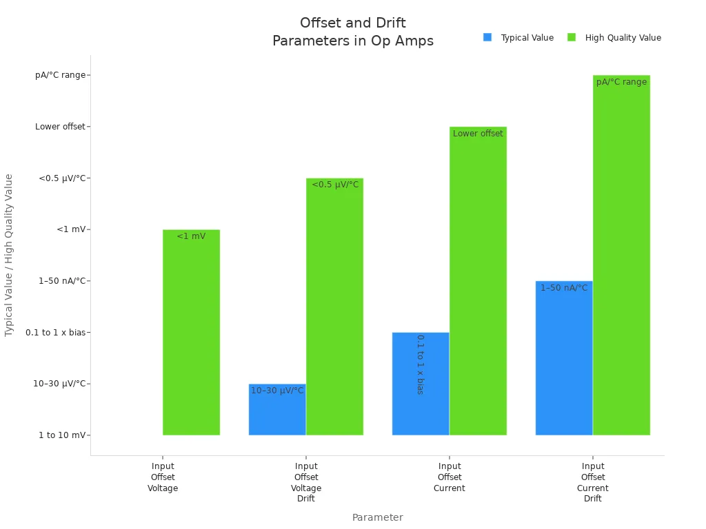
Manufacturers use several methods to specify and test offset and drift. They calibrate each operational amplifier at the factory, often using matched components and temperature cycling. Some designs use digital calibration or chopper-stabilized circuits to keep offset and drift very low. These steps ensure the differential amplifier maintains high accuracy and stable voltage gain over time.
Applications of Differential Amplifiers
Differential amplifiers play a vital role in many modern electronic systems. Their ability to amplify only the difference between two signals while rejecting noise makes them essential in several fields. Below are some of the key uses of operational amplifiers in real-world applications:
- Medical instrumentation
- Data acquisition systems
- Audio equipment
- Industrial control and automation
Instrumentation
Medical devices rely on operational amplifiers for accurate signal processing. Differential amplifiers extract tiny electrical signals from the human body, such as those in ECG or EEG machines. These signals are often weak and surrounded by noise. The advantages of differential amplifiers include high common-mode rejection and precise amplification, which help isolate true biomedical signals. The table below highlights how these amplifiers enhance signal accuracy in medical instrumentation:
| Feature/Aspect | Explanation |
|---|---|
| Common-Mode Rejection Ratio (CMRR) | Rejects noise and interference, focusing on the real signal. |
| High Input Impedance | Prevents signal loss from weak sources like electrodes. |
| Instrumentation Amplifier | Combines buffers and differential stages for high gain and noise rejection. |
| Amplification of Difference Only | Ensures only the true signal is amplified, not the noise. |
Sensor Signal Amplification
Industrial automation depends on operational amplifiers to boost sensor signals. Many sensors produce low-level voltages that need amplification before further processing. Differential amplifiers improve signal clarity by rejecting common-mode noise. This feature is especially important in factories, where electrical interference is common. The advantages of differential amplifiers include better signal-to-noise ratio and reliable data for control systems. These amplifiers also prepare signals for analog-to-digital converters, ensuring accurate measurements.
Motor and Servo Control
Motor and servo control systems use operational amplifiers to maintain precision and reject noise. Differential amplifiers process feedback signals from encoders or sensors. They amplify only the difference between two complementary signals, which helps remove unwanted noise. Balanced impedance in the amplifier design keeps the signal stable. These features allow for precise control of motor speed and position, which is one of the key uses of operational amplifiers in robotics and automation.
Tip: Engineers choose differential amplifiers for environments where accuracy and noise rejection are critical. Their unique design supports reliable amplification in challenging conditions.
Op-Amp Design Considerations
Resistor Matching
Engineers face several challenges when designing operational amplifier circuits for differential signal processing. One major challenge involves matching resistors precisely. The operational amplifier relies on resistor ratios to set gain and maintain high common-mode rejection. Even small mismatches in resistor values can reduce common-mode rejection ratio (CMRR) and introduce errors in gain. For example, mismatches as small as 1% can lower CMRR to about 34 dB, while 0.01% matching can raise it to 74 dB or higher. Temperature changes, aging, and mechanical stress can cause resistor values to drift, affecting gain and common-mode performance.
Supplying reference voltages also presents difficulties. Simple resistor dividers may unbalance the subtractor circuit, reducing gain accuracy and CMRR. Using low-impedance buffers between the divider and the operational amplifier’s reference input helps eliminate impedance mismatch and temperature tracking problems. Selecting resistors with low temperature coefficients and arranging them to minimize thermal effects improves stability. Integrated resistor networks, such as those found in advanced operational amplifier chips, offer tight matching and help maintain gain accuracy over time.
| Failure Mode | Description | Mitigation Strategies |
|---|---|---|
| Common-Mode Gain | Output errors from resistor imbalance and common-mode voltage changes. | Use precisely matched resistors; select operational amplifiers with high CMRR; trim resistor networks. |
| Input Bias Currents | Voltage drops across input resistors cause offset errors. | Add compensating resistors; use operational amplifiers with low bias currents. |
| Offset Voltage | Output deviates from zero due to internal mismatches. | Use offset trimming; select low-offset operational amplifiers. |
| Latch-up | Output saturates when input voltage exceeds supply rails. | Avoid input voltages outside supply rails; use operational amplifiers with latch-up protection. |
| Stability Issues | Phase shifts cause instability or oscillation. | Design for adequate phase margin; minimize capacitive loading; use unity-gain stable operational amplifiers. |
CMRR Optimization
Maximizing common-mode rejection ratio (CMRR) in operational amplifier circuits requires careful attention to layout and component selection. Engineers use balanced and symmetrical resistor networks with precisely matched values, ideally within 0.1%, to improve common-mode rejection. High-precision resistors and laser trimming help maintain matching. Selecting resistors with low temperature coefficients or arranging them to minimize thermal effects ensures temperature stability.
Buffering techniques play a key role in optimizing CMRR. Buffering operational amplifier inputs with voltage followers increases input impedance and reduces loading effects. This isolation preserves signal integrity and improves reliability. Three-op-amp instrumentation amplifier configurations allow gain adjustment with a single resistor, maintaining high common-mode rejection and stable gain. Shielding sensitive parts, keeping wiring short, and minimizing parasitic capacitance also help preserve signal integrity.
- Balanced resistor networks and buffering improve gain accuracy and common-mode rejection.
- Three-op-amp instrumentation amplifiers offer flexible gain control and high CMRR.
- Careful layout and component selection reduce errors and enhance operational amplifier performance.
Tip: Engineers should always consider resistor matching, buffering, and layout when designing operational amplifier circuits for differential signal processing.
Differential op amps help electronic systems achieve accurate and reliable signal processing.
- They provide high input impedance and strong noise rejection, which keeps signals clear in noisy places.
- Their flexible designs support many uses, from medical devices to industrial controls.
- New features like zero-drift and rail-to-rail input/output make them ready for future challenges.
As technology advances, differential op amps will remain a key part of modern electronics, powering smarter and more precise devices.
FAQ
What is the main advantage of a differential op amp?
A differential op amp amplifies only the voltage difference between two inputs. This feature helps reject noise and interference that appear on both inputs. Engineers use this property to get accurate signals in noisy environments.
Why do engineers care about high input impedance?
High input impedance means the op amp draws very little current from the signal source. This prevents signal loss and keeps measurements accurate. Sensitive sensors and weak signals benefit most from this feature.
How does CMRR affect signal quality?
CMRR, or common-mode rejection ratio, shows how well the op amp blocks unwanted noise. A high CMRR means the amplifier ignores signals common to both inputs. This keeps the output clean and reliable.
Where do people use differential op amps?
People use differential op amps in medical devices, audio equipment, industrial controls, and sensor systems. These amplifiers help process small signals and remove noise, making them vital in many modern electronics.