What Makes Current Splitters Essential for Modern Electronics
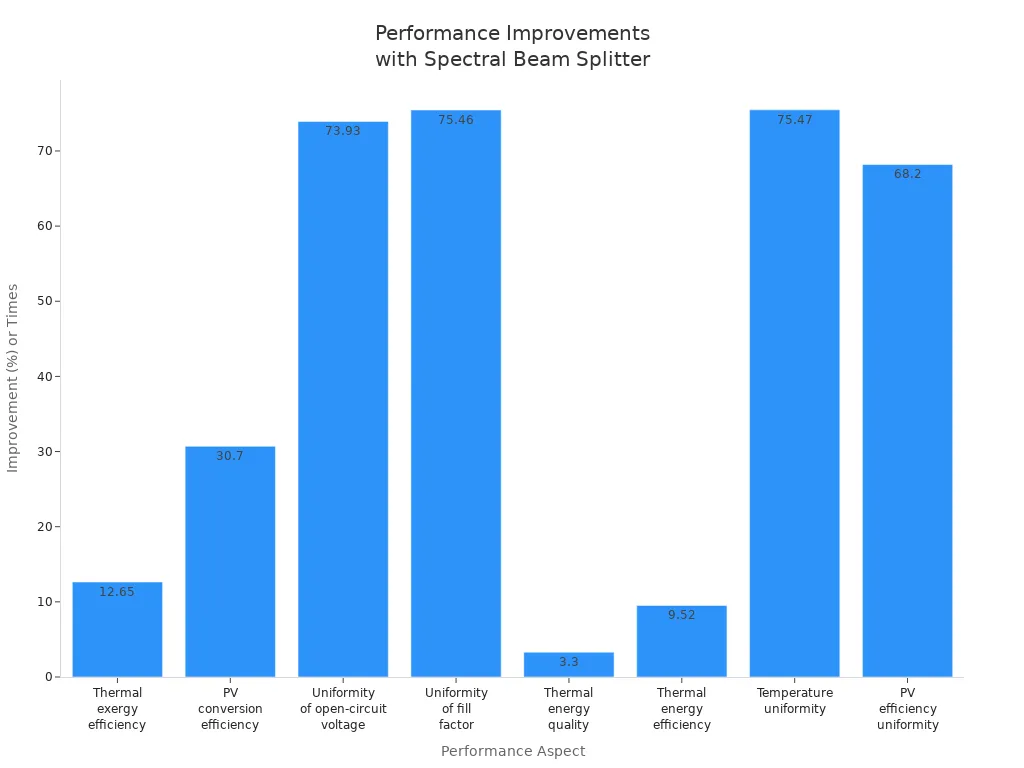
Current splitters play a vital role in modern electronics by ensuring balanced current flow, which boosts both system stability and efficiency. Devices like electric meters, LED lighting, and RF systems rely on power splitters to distribute current or signals safely and accurately. Power splitters help prevent overheating and improve measurement accuracy. In advanced systems, such as CPV/T setups, a splitter can increase thermal exergy efficiency by 12.65% and photovoltaic conversion efficiency by 30.70%. The chart below shows how a spectral beam splitter enhances several performance aspects, including voltage and temperature uniformity.
Power splitters and current splitters remain essential for safety, system reliability, and optimal performance in today’s electronics.
Key Takeaways
- Current splitters divide electrical current safely to protect devices and improve system balance.
- Passive and RF power splitters serve different needs, with RF splitters handling high-frequency signals in communication systems.
- Power splitters are vital in electric meters, LED lighting, and RF networks for accurate measurement and efficient signal distribution.
- High efficiency, strong isolation, and proper power handling make splitters reliable and safe in modern electronics.
- Choosing the right splitter depends on the system’s current, voltage, number of outputs, and environmental needs.
Current Splitter Basics
Definition
A current splitter is a device or circuit that divides electrical current into two or more separate paths. Engineers use splitters to control how much current flows through each part of a system. This helps protect sensitive components and ensures that each branch receives the right amount of current. In many electronic devices, a splitter keeps the system safe and balanced. For example, in an electric meter, a splitter allows the device to measure current accurately by sending part of the current to the measuring circuit and the rest to the main load.
Note: Splitters come in many forms, such as simple resistor networks or more complex electronic modules. Each type serves a specific purpose in managing current flow.
How It Works
A splitter works by using the rules of electricity to divide current between different branches. When engineers design a splitter, they often use resistors or other components to set how much current goes to each path. The main principle behind a splitter is that the voltage across all branches stays the same, but the current splits based on the resistance in each branch.
Ohm’s Law and Kirchhoff’s Current Law guide how a splitter operates. Ohm’s Law says that current equals voltage divided by resistance. Kirchhoff’s Current Law states that the total current entering a point must equal the total current leaving that point. Because of these laws, a splitter divides the total current so that each branch gets a share based on its resistance. If one branch has lower resistance, it receives more current. If another branch has higher resistance, it receives less.
Here is a simple table showing how a splitter divides current:
| Branch Resistance | Current Share |
|---|---|
| Low | High |
| Medium | Medium |
| High | Low |
This method allows a splitter to keep the system balanced, even if the supply voltage changes. The ratio of current in each branch depends only on the resistance values. This makes the splitter a reliable tool for dividing current in many electronic circuits.
Types of Power Splitters
Passive Power Splitter
A passive power splitter divides electrical current or signals without using any external power source. Engineers often use this type of splitter in multi-line power systems, electric meters, and LED lighting. The passive power splitter relies on components like resistors or transformers to split the current. In an electric meter, a splitter helps measure the current by sending part of it to the measuring circuit. In LED lighting, a power splitter ensures each light receives the right amount of current, which keeps the lights bright and safe.
The passive power splitter does not add energy to the system. It only divides what is already there. This makes the splitter simple and reliable. Many power splitters in home and industrial systems use this design. The power combiner works in the opposite way, joining currents from different sources into one path. Both the splitter and the power combiner help manage current flow and protect devices.
RF Power Splitters
RF power splitters work with radio frequency signals. These splitters play a key role in communication systems, such as broadcasting, RF testing, and antenna arrays. The RF power splitter takes an input signal and divides it evenly across several output ports. Each output port receives the same amount of signal power. This even distribution is important for balanced signal routing in networks.
RF power splitters focus on keeping the signal strong and clear. They aim to minimize insertion loss, so the signal does not weaken as it splits. Proper impedance matching helps reduce signal reflection and keeps the signal quality high. The power splitter and power combiner often work together in RF systems to manage signals between devices.
RF power splitters are different from passive power splitters because they handle high-frequency signals and require careful design to maintain signal integrity.
Some common uses for RF power splitters include:
- Distributing signals to multiple antennas in a communication system
- Sending test signals to several devices at once
- Balancing signal levels in broadcasting equipment
- Connecting multiple receivers to a single antenna
- Ensuring equal power levels in multi-device RF setups
- Reducing signal loss in complex networks
- Supporting antenna arrays for better coverage
- Maintaining signal strength across all outputs
- Preventing signal reflection with impedance matching
- Working with power combiners to join signals when needed
The splitter and power combiner both play vital roles in modern electronics. Power splitters help manage current and signal flow, while RF power splitters keep communication systems running smoothly.
Applications in Modern Systems
Electric Meter Circuits
Electric meter circuits rely on power splitters to ensure accurate measurement and safe operation. In these systems, a splitter directs a controlled portion of the current through sensitive measuring instruments, such as shunt resistors. This method protects the meter from overload and maintains precise readings. Power splitters also help distribute current among different components, preventing any single part from carrying too much load. Many modern electric meters use split-core current transducers. These devices offer several advantages:
- The openable core design allows installation without disconnecting wires.
- Non-invasive measurement means technicians can clamp the device around live conductors.
- Quick installation reduces downtime and makes retrofitting easier.
- Compact size fits tight spaces and portable setups.
- Durable construction supports repeated use.
Power splitters and power combiner devices work together in electric meter circuits. The power combiner joins currents from multiple sources, while the splitter divides the flow for measurement and distribution. This teamwork ensures the system remains balanced and safe.
Tip: Split-core current transducers make upgrades and maintenance much simpler in busy electrical panels.
LED Lighting
LED lighting systems use power splitters to manage current and signal distribution across multiple light strips. A splitter ensures each LED receives the correct amount of current, which keeps brightness consistent and prevents overheating. Power splitters also allow a single controller to manage several LED strips at once. For example, devices like the SA6 6 Way Signal Splitter amplify and multiply SPI signals, enabling synchronized control of many lights. This setup increases the scalability of LED installations and reduces the need for extra controllers.
Power splitters maintain signal integrity and synchronization, which is essential for smooth lighting effects. The power combiner can join signals from different controllers, making complex lighting patterns possible. In large displays or architectural lighting, power splitters and power combiner units help create uniform and reliable illumination.
- Power splitters distribute current evenly to all LED strips.
- Signal distribution remains stable, even in large setups.
- Power combiner units support advanced lighting designs.
LED lighting benefits from power splitters by achieving efficient operation, lower costs, and easier expansion.
RF and Signal Distribution
RF and signal distribution networks depend on specialized power splitters and rf power splitters for optimal performance. These splitters divide radio frequency signals among multiple outputs, ensuring each device receives a balanced and strong signal. Engineers often use active differential splitters with fully differential amplifiers and baluns to convert single-ended signals to differential ones. This approach allows for balanced splitting and amplification.
Power splitters in RF systems provide excellent impedance matching, which minimizes signal reflection and maximizes power transfer. Each output channel can have independent gain control, so engineers can adjust signal strength as needed. Load isolation ensures that changes in one output do not affect others, which is critical in automated test equipment and communication systems.
- Power splitters and rf power splitters enable balanced signal distribution in antenna arrays and broadcasting.
- Engineers can scale the number of outputs by adjusting resistor values and feedback elements.
- Transformer coupling at the input offers DC isolation and handles common mode voltages.
- Wideband fully differential amplifiers support high-frequency signals with low distortion.
- Power combiner devices join signals from different sources, supporting complex network designs.
Power splitters and rf power splitters overcome the limitations of passive splitters, such as insertion loss and load dependency. They offer customizable gain and frequency response, making them ideal for modern RF and signal distribution networks.
Note: Power splitters and power combiner units are essential for reliable signal distribution in communication, broadcasting, and automated testing.
Common Applications of Power Splitters and Signal Distribution
- Biasing transistors for stable amplifier operation
- Distributing current in power supplies to prevent overload
- Directing current through sensors for accurate measurement
- Voltage-to-current conversion for transducer interfacing
- Sharing signals between parallel pathways with minimal loss
- Electrical metering for safe and precise readings
Power splitters, rf power splitters, and power combiner devices form the backbone of modern electronic systems. They ensure accurate measurement, efficient lighting, and robust signal management across a wide range of applications.
Performance Factors
Efficiency
Efficiency measures how well a power splitter divides current or signals without wasting energy. Engineers look for splitters that transmit light or electrical signals with minimal loss. In modern electronics, power splitters often reach photon transmission efficiency above 80%. This high efficiency means the splitter sends most of the light or signal to the output, which improves system performance. Some splitters increase light sensitivity by a factor of four compared to older filters. The sensor fill-factor, such as 0.5, also affects how much energy the system uses. Power splitters help reduce light loss and boost imaging sensitivity in devices like cameras and sensors.
- Photon transmission efficiency above 80%
- Four times better light sensitivity than traditional filters
- Sensor fill-factor impacts overall efficiency
Power splitters make electronic systems more reliable and energy-efficient. They support signal distribution in devices that need strong and clear signals.
Isolation
Isolation keeps different parts of an electronic system safe from electrical faults and noise. Power splitters with strong isolation separate the input from the output, protecting sensitive equipment. Engineers use isolation to prevent ground loop errors and reduce noise. This improves signal distribution and keeps measurements accurate. The table below shows how isolation affects safety and signal integrity:
| Aspect | Impact on System Safety and Signal Integrity |
|---|---|
| High-voltage isolation | Separates input from power and outputs, protecting against surges and noise |
| Ground loop error elimination | Prevents errors caused by grounding differences, ensuring accurate signals |
| Noise reduction | Electrical isolation reduces noise interference, improving signal clarity |
| Use of USB isolators | Recommended during configuration to avoid ground loop errors |
| Rugged design and EMI immunity | Enhances operational safety and maintains signal integrity in harsh environments |
| 1500V isolation rating | Provides strong protection against electrical faults and interference |
Power splitters with high isolation ratings keep systems safe in industrial and laboratory settings. Power combiner units also benefit from isolation, especially when joining signals from different sources.
Power Handling
Power handling shows how much energy a power splitter can manage without damage. Industrial applications need splitters that work with high power and wide frequency ranges. The table below lists several models and their maximum power handling:
| Product Model | Frequency Range (MHz) | Max Power Handling (Watts) | Notes |
|---|---|---|---|
| Vertical Launch Power Divider Combiner (PVL210) | 698 - 2700 | 40 | SMA connectors, wideband RF splitter |
| Reverse Polarity SMA Splitter Combiner (RP2120) | 698 - 2700 | 40 | 2.4 GHz Wi-Fi and wireless LAN/WAN |
| L-band Splitters (PD592A, PD592B, PD552A, PD552B, PD512A, PD512B, PD502A) | 698 - 2700 | 40 | Various connectors (TNC, BNC, SMA, N) |
| IP67 Outdoor Splitter Combiner (PD2458) | 2400 - 6000 | 30 | Weatherproof, N-type connectors |
| IP67 Outdoor SMA Splitter Combiner (PD2558) | 2400 - 6000 | 30 | Weatherproof, SMA connectors |
| UHF/RFID Power Divider Combiner (PD2320) | 350 - 1000 | 30 | N-type connectors |
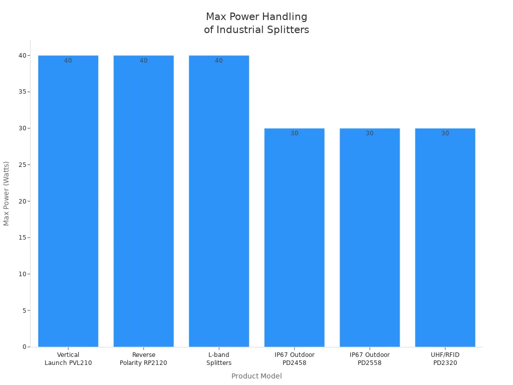
Power splitters with high power handling work well in wireless networks, outdoor installations, and RF signal distribution. Power combiner devices also need strong power handling to join signals safely. Engineers choose splitters and combiners based on the needs of each system.
Choosing a Current Splitter
Application Needs
Every electronic system has unique requirements, so engineers must match the right splitter to the job. Some circuits need to scale voltage for sensors or ADC inputs. In these cases, voltage dividers work well, but they cannot handle large or changing currents without causing voltage drops. Circuits that need stable voltage for devices with higher or changing current demands often use voltage regulators or switching power supplies. These options provide better efficiency and voltage stability.
For example, the '10% Rule' helps engineers design voltage dividers by making sure the bleeder current is about ten times the load current. This keeps voltage steady and reduces waste. If the bleeder current is too high, the circuit wastes energy and produces heat. If it is too low, the voltage becomes unstable. Engineers also use splitters for biasing transistors, impedance matching in RF circuits, and scaling sensor outputs for microcontrollers.
Tip: Always consider the type of load and the stability needed before choosing a splitter.
Selection Tips
Choosing the best current splitter involves checking several important factors. The table below summarizes what to look for:
| Factor | Why It Matters |
|---|---|
| Signal Integrity | Keeps signals clean and free from noise |
| Build Quality | Ensures durability and reliability |
| Compatibility | Matches connectors and signal types |
| Number of Outputs | Meets the needs of your setup |
| Transmission Distance | Active splitters help with longer distances |
| Active vs. Passive | Powered splitters amplify signals; passive do not |
| Power/Current Ratings | Handles the required electrical load safely |
| Protocol Compatibility | Supports needed standards and formats |
| Environmental Fit | Works in the right temperature and conditions |
| Price Point | Balances cost with features and durability |
Recent advances in splitter design include miniaturization, energy-efficient circuits, and smart features like real-time monitoring. Some modern splitters use advanced current mirroring and translinear loop designs to improve precision and reduce power use. These improvements help splitters work better in small, high-tech devices.
A current splitter that matches the system’s needs will improve performance, safety, and reliability.
Current splitters and power splitters help electronic systems achieve high efficiency, safety, and reliability. They protect devices from overload and support accurate measurements. Engineers should match splitters to specific application needs and check performance ratings.
- Perform accurate load calculations before installation.
- Use certified equipment that meets safety standards.
- Follow updated electrical codes and maintain detailed documentation.
Staying informed about new technologies and best practices, such as using energy management systems and proper PCB design, helps maintain safe and reliable operation in high-demand environments.
FAQ
What is the main purpose of a current splitter?
A current splitter divides electrical current into separate paths. Engineers use it to balance loads, protect devices, and improve measurement accuracy in electronic systems.
How does a current splitter improve safety?
A current splitter prevents overload by sending the right amount of current to each device. This reduces the risk of overheating and electrical faults.
Where can someone find current splitters in daily life?
Current splitters appear in electric meters, LED lighting systems, and radio frequency networks. These devices help manage current and signals in homes and businesses.
What is the difference between a passive and an RF power splitter?
A passive power splitter divides current or signals using resistors or transformers. An RF power splitter handles high-frequency signals and maintains signal strength for communication systems.
How does someone choose the right current splitter for a project?
Engineers check the system’s voltage, current needs, and number of outputs. They select splitters with proper ratings and features for the application.