Your Complete UART Guide for Projects in 2025
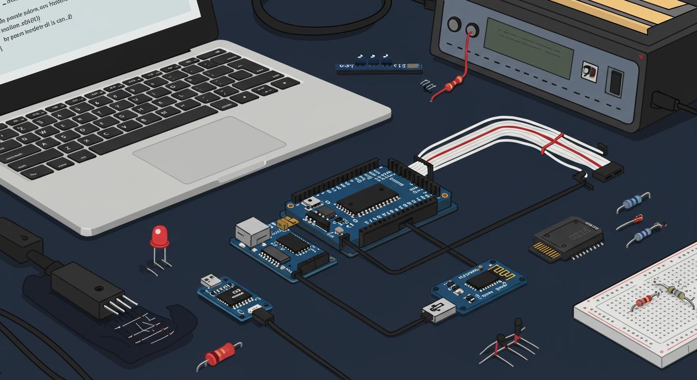
The Universal Asynchronous Receiver/Transmitter (UART) is a fundamental circuit. It enables serial communication between your electronic devices. This technology offers robust communication using just two main wires (Tx/Rx), making it simple and widely supported.
Did You Know? 💡 The UART chip market is projected to surpass $2 billion in 2025. This growth is fueled by its adoption in over 300 million new IoT devices in Europe alone, which rely on uart for efficient data exchange.
Key Takeaways
UART helps devices talk to each other using only two wires.
UART uses extra bits to time data without a shared clock.
Devices must use the same settings like speed and data bits to communicate.
Connect the TX pin of one device to the RX pin of the other, and share a ground wire.
Use a logic level shifter if devices have different voltage levels.
Arduino uses
HardwareSerialfor fast communication andSoftwareSerialfor slower tasks.The Raspberry Pi needs its serial port enabled to use UART.
DMA helps microcontrollers send data without using the main processor.
Fundamentals of UART Serial Communication
To master UART, you first need to understand its core principles. The protocol's strength lies in its simplicity, which begins with how it synchronizes data between two devices without a shared clock signal.
Asynchronous vs. Synchronous
Electronic communication falls into two main categories: synchronous and asynchronous. The key difference is timing.
The Role of a Shared Clock
Synchronous communication relies on a shared clock signal. The sender and receiver both use this clock to time the transmission of data bits. This method is very efficient for sending large blocks of data because the overhead is low.
Syncing Without a Clock
Asynchronous communication, which UART uses, does not share a clock. Instead, you add extra bits to the data itself to handle timing. This start-stop method of synchronization was first patented by Howard Krum as early as 1916. While this asynchronous approach adds about 20% overhead to each character's transmission, it simplifies the wiring and configuration. This makes asynchronous communication ideal for the character-by-character data transmission common in embedded systems.
The UART Data Frame
You send data via UART in packets, or "frames." Each frame has a specific structure that both devices must agree on. This is a key part of your initial configuration.
Start and Stop Bits
Every data frame begins with a Start Bit. This bit tells the receiver that a new transmission is starting. The frame ends with one or two Stop Bits, signaling the end of the transmission.
Data Bits (7, 8, or 9)
Following the start bit is the actual data payload. You can configure this to be 7, 8, or 9 bits long.
7 bits: Efficient for sending standard ASCII characters.
8 bits: The most common size, perfect for sending a full byte of data.
9 bits: Often used for advanced purposes, like adding an extra parity bit or addressing devices on a multi-drop bus.
The Optional Parity Bit
After the data bits, you can include an optional Parity Bit. This bit provides a simple form of error checking. The sender sets this bit to make the total number of '1's in the data either even or odd. The receiver performs the same count. If they don't match, the receiver knows the data was corrupted during transmission.
LSB-First Data Order
UART sends the data bits from least-significant bit (LSB) to most-significant bit (MSB). This is a standard convention you should be aware of when debugging.
Key Configuration Parameters
For two devices to have a successful serial communication, you must give them the exact same configuration. A mismatch in any of these settings is the most common cause of errors.
Baud Rate
Baud rate is the speed of the data transmission, measured in bits per second. Both devices must operate at the same baud rate. Common rates include 9600 for simple devices and 115200 for medical equipment requiring faster data transfer.
Frame Structure
This configuration defines the makeup of your data frame. You often see it written as a shorthand, like 8N1.
Example:
8N1This common configuration means:
8 data bits
No parity bit
1 stop bit
Hardware Flow Control (RTS/CTS)
For high-speed data transmission, the receiver's buffer can fill up. Hardware flow control uses two extra wires, Request to Send (RTS) and Clear to Send (CTS), to manage this. The receiver can signal the sender to pause the transmission, preventing data loss. This configuration is an important feature that helps the uart transmit data reliably.
Physical Wiring and Voltage Levels
After you configure the software, you must physically connect your devices. Correct wiring and matching voltage levels are critical for a stable uart connection. Mistakes here can lead to garbled data or even damage your components.
The Basic Connection
A basic uart setup requires just three wires. This simplicity is one of the protocol's greatest strengths.
The TX-to-RX Crossover
You must connect the transmitter (TX) pin of one device to the receiver (RX) pin of the other. This crossover ensures that data sent from one device is received by the other.
Device A TX → Device B RX
Device B TX → Device A RX
The Common Ground (GND)
Both devices must share a common ground reference. You achieve this by connecting their ground (GND) pins together. Without a shared ground, the devices cannot correctly interpret the high and low voltage signals, leading to communication failure.
Understanding Logic Levels
Logic levels define the voltages that represent a digital '1' (HIGH) and '0' (LOW). You must ensure your communicating devices use compatible logic levels.
TTL vs. CMOS (5V & 3.3V)
Most modern microcontrollers use either 5V or 3.3V logic. These systems follow specific voltage standards, like TTL for older 5V devices and CMOS for modern 3.3V devices. A 3.3V device can often understand a 5V signal, but a 5V device may not reliably read a 3.3V signal as HIGH.
Logic Level | Parameter | 5V TTL (Volts) | 3.3V CMOS (Volts) |
|---|---|---|---|
Output HIGH | VOH (Min) | 2.7 | 2.4 |
Input HIGH | VIH (Min) | 2.0 | N/A |
Output LOW | VOL (Max) | 0.4 | N/A |
Input LOW | VIL (Max) | 0.8 | N/A |
The RS-232 Standard
Some older equipment, like industrial machines or PCs with serial ports, uses the RS-232 standard. This standard uses much higher voltages and inverted logic.
For an RS-232 driver, a logic '1' is a negative voltage (–3V to –15V), and a logic '0' is a positive voltage (+3V to +15V). You must never connect an RS-232 device directly to a microcontroller's uart pins, as the high voltage will cause permanent damage.
Interfacing Mismatched Voltages
When your devices use different logic levels, you need a way to translate the signals safely.
Using Logic Level Shifters
A logic level shifter is a small circuit that safely converts signals between two different voltage levels, like 5V and 3.3V. When choosing one, consider its speed. Simple MOSFET-based shifters are often too slow for high-speed uart, topping out around 400kHz. For faster communication, you should use a dedicated IC. Also, check that the shifter can supply enough current for your application, as some basic modules provide as little as 3mA.
Using a MAX232 IC
To interface a microcontroller with an RS-232 device, you need a special transceiver IC like the MAX232. This chip converts the microcontroller's low-voltage TTL/CMOS signals into the high-voltage, inverted signals required by RS-232, and vice-versa.
Practical UART Implementation
Theory is important, but putting it into practice is where you truly learn. This section guides you through setting up UART communication on three of the most popular platforms in modern electronics: Arduino, Raspberry Pi, and your PC.
Arduino Integration
Arduino makes serial communication incredibly accessible. Most boards have at least one built-in hardware UART, which is the easiest and most reliable way to get started.
HardwareSerial Port
Arduino's HardwareSerial library uses the dedicated UART hardware on the microcontroller. This approach offers the best performance. For example, an Arduino Uno has one hardware serial port on digital pins 0 (RX) and 1 (TX). These pins are also connected to the onboard USB-to-UART converter, so you can talk to your computer directly. Boards like the Arduino Mega offer multiple hardware ports (Serial, Serial1, Serial2, etc.), giving you more options.
Performance Note 📝 You should always choose
HardwareSerialfor high-speed tasks. It is the only option for baud rates like 115200. Software-based solutions cannot handle these speeds.
A key detail is the serial buffer. Most Arduinos have a 64-byte buffer to hold incoming data. If this buffer fills up, any new incoming data is simply discarded until you read from the buffer to make space.
Arduino Code Example
Here is a simple sketch. It reads a character from the serial port, adds one to it (e.g., 'a' becomes 'b'), and sends it back. This is a great way to test your connection.
// Your Complete UART Guide for Projects in 2025
// Arduino HardwareSerial Echo Example

void setup() {
  // Initialize serial communication at 9600 bits per second.
  // This is the baud rate.
  Serial.begin(9600);

  // The 'if (Serial)' check is mainly for boards like the Leonardo.
  // It waits for the USB serial connection to be ready.
  // On an Uno, this always returns true immediately.
  while (!Serial) {
    ; // wait for serial port to connect. Needed for native USB port only
  }

  Serial.println("Arduino is ready. Send me a character!");
}

void loop() {
  // Check if there is any incoming data available to read.
  if (Serial.available() > 0) {
    // Read the incoming byte.
    char incomingChar = Serial.read();

    // Print what you received.
    Serial.print("I received: ");
    Serial.println(incomingChar);

    // Modify the data and send it back.
    char outgoingChar = incomingChar + 1;
    Serial.print("I am sending back: ");
    Serial.println(outgoingChar);
  }
}
The SoftwareSerial Library
What if you need another serial port, but your board's hardware UARTs are already in use? The SoftwareSerial library is your solution. It lets you use almost any two digital pins for serial communication.
However, this flexibility comes at a cost. Software serial communication consumes more of the CPU's processing power compared to its hardware counterpart. This makes it less efficient and unsuitable for high-speed data transfers. You should reserve SoftwareSerial for low-speed applications, like communicating with a GPS module that updates once per second.
Raspberry Pi Integration
The Raspberry Pi is a powerful single-board computer with GPIO pins that include a UART. You can use it to communicate with Arduinos, sensors, and other serial devices.
Enabling the GPIO UART
By default, the Raspberry Pi uses its hardware UART for the Linux serial console. You must disable this feature to use the UART for your own projects.
Open a terminal on your Raspberry Pi.
Type
sudo raspi-config.Navigate to
3 Interface Options.Select
I6 Serial Port.When asked "Would you like a login shell to be accessible over serial?", select No.
When asked "Would you like the serial port hardware to be enabled?", select Yes.
Reboot your Pi.
Your UART is now available on the GPIO pins. On most models, including the Pi 4 and Pi 5, these are:
GPIO 14 (Pin 8) - TXD
GPIO 15 (Pin 10) - RXD
Python Code Example
Python's pyserial library is the standard for controlling the serial port. It is a pure Python module with no dependencies, making it easy to install and use. First, install it with pip: pip install pyserial.
The library gives you a file-like interface with read and write functions. Here is a script to transmit data.
# Your Complete UART Guide for Projects in 2025
# Raspberry Pi pyserial Example

import serial
import time

# Configure the serial port.
# The port name may be '/dev/ttyS0' or '/dev/serial0'.
# Use the same baud rate as your other device.
try:
    ser = serial.Serial('/dev/serial0', 9600, timeout=1)
    ser.reset_input_buffer()
    print("Serial port opened successfully.")

    while True:
        # Send a string. The 'b' prefix makes it a byte string.
        ser.write(b"Hello from Raspberry Pi!\n")
        print("Sent: Hello from Raspberry Pi!")
        time.sleep(2)

except serial.SerialException as e:
    print(f"Error: Could not open serial port. {e}")

except KeyboardInterrupt:
    print("Program terminated by user.")
    ser.close()
Pi-to-Arduino Connection
Connecting a Pi to an Arduino is a common task. Remember the crossover rule:
Pi TX (GPIO 14) → Arduino RX (e.g., Pin 0)
Pi RX (GPIO 15) → Arduino TX (e.g., Pin 1)
Pi GND → Arduino GND
Voltage Warning! ⚠️ The Raspberry Pi's GPIO pins use 3.3V logic. An Arduino Uno uses 5V logic. Connecting a 5V Arduino TX pin directly to a 3.3V Pi RX pin can damage the Pi. You must use a logic level shifter to safely connect them.
PC-to-Microcontroller Link
Sometimes, you just need to connect your project directly to your computer. A USB-to-UART adapter is the perfect tool for this job.
USB-to-UART Adapters
These small boards convert USB signals from your computer into UART signals that your microcontroller can understand. They are essential for programming boards without a built-in USB port or for debugging serial communication. Three chips dominate this market:
Chip | Key Features | Best For |
|---|---|---|
Extremely robust and reliable. Excellent driver support on all OSes. Supports high baud rates up to 3M. | Professional projects where reliability is critical. | |
Very reliable and easy to use. Drivers are often built into modern OSes, making it plug-and-play. | Hobbyists and professionals who want a hassle-free setup. | |
A very low-cost and widely available option. Good driver support, but may require manual installation. | Budget-conscious projects and common Arduino clones. |
Many of these adapters include a jumper to switch between 3.3V and 5V logic levels, making them highly versatile.
Finding Your COM Port
Your computer assigns a COM port name to the USB-to-UART adapter. You need this name to connect to it.
Windows: Open the Device Manager. Look under "Ports (COM & LPT)". Your adapter will appear as something like "USB-SERIAL CH340 (COM3)".
macOS / Linux: Open a terminal and run
ls /dev/tty.*. Your adapter will likely appear as/dev/tty.usbserial-XXXX(macOS) or/dev/ttyUSB0(Linux).
Using a Serial Terminal
A serial terminal is a software program that lets you view and send serial data.
Arduino IDE Serial Monitor: This tool is integrated directly into the Arduino IDE. It is perfect for quick tests. You can select the baud rate and see incoming data. However, it is a basic tool and cannot, for example, hide special characters like color codes.
PuTTY: A lightweight and powerful free tool for Windows and Linux. Beyond serial, it also supports SSH and Telnet. For serial use, you select the COM port and baud rate. Its key advantage is the ability to log all serial communication directly to a file, which is invaluable for debugging complex issues.
Advanced Topics and Troubleshooting
You have the basics down. Now you can explore advanced techniques and learn how to solve common problems. This knowledge will help you build more robust and efficient projects.
Common Problems and Fixes
When your uart communication fails, you can follow this checklist to find the issue. Start with the most likely causes first.
Garbled Data
If you see strange or unreadable characters, you likely have a configuration mismatch.
Incorrect Baud Rate: This is the most common reason for garbled data. You must ensure both devices are set to the exact same speed.
Hardware Wiring Issues: Check for a solid ground connection. Also, confirm you are not mixing logic levels, like connecting a 5V device to a 3.3V pin without a shifter.
Other Parameters: Verify that both devices use the same number of data bits, stop bits, and the same parity setting (e.g.,
8N1).
No Data Transmission
If you receive nothing at all, the problem is usually physical.
Check that your TX and RX lines are crossed correctly (TX-to-RX, RX-to-TX).
Ensure all wires are securely connected to the correct pins.
Confirm both devices share a common ground (GND) connection.
Logic Level Mismatch
Connecting devices with different voltages (e.g., 5V and 3.3V) can cause unreliable transmission or even damage your hardware. Always use a logic level shifter to protect your components.
Framing and Parity Errors
These errors occur when the receiver detects an invalid stop bit or a parity mismatch. They almost always point back to a mismatched configuration in your baud rate or frame structure settings.
High-Performance Techniques
For projects that handle a lot of serial data, you can use Direct Memory Access (DMA) to improve performance.
What is Direct Memory Access (DMA)?
DMA is a feature on a microcontroller that allows peripherals to transfer data directly to and from memory. This happens without involving the main processor (CPU).
Offloading the CPU with DMA
In a normal uart transmission, the CPU must stop its current task to handle every single byte of incoming or outgoing data. With DMA, you tell the DMA controller where the data is and how much to send. The DMA then manages the entire transmission on its own, freeing the CPU to perform other tasks. This is crucial for high-speed applications.
Use Cases for DMA
You should use DMA for any high-throughput data streaming. When receiving data, you can use a ring buffer. The DMA controller fills this buffer in the background. Your main code can then check for a DMA completion interrupt to know when a block of data is ready for processing. This strategy prevents the CPU from constantly polling for new bytes and makes your data transmission much more efficient.
UART vs. I2C vs. SPI
UART is great for point-to-point links, but other protocols exist for different needs. Choosing the right one is key.
Point-to-Point (UART)
UART is an asynchronous protocol ideal for connecting two devices. It is simple to implement but does not easily support multiple devices on the same two wires.
Multi-Device Bus (I2C)
I2C is a synchronous protocol that uses two wires to connect many devices. It is easy to chain multiple devices together, making it perfect for reading from various sensors.
High-Speed Data Streaming (SPI)
SPI is another synchronous protocol that offers the fastest data transmission speeds. It is more complex to wire as the number of devices increases, but it is the best choice for high-speed needs like displays or SD cards.
Quick Comparison 📊 This table helps you choose the best protocol for your project.
Protocol | Max Speed (Typical) | Wires | Device Support |
|---|---|---|---|
UART | ~115.2 Kbps | 2 (TX, RX) | 2 Devices (Point-to-Point) |
I2C | Up to 3.4 Mbps | 2 (SCL, SDA) | Up to 128 Devices |
SPI | >10 Mbps | 4+ | Multiple (Limited by CS pins) |
You now see that uart is a simple yet powerful tool for your projects. This guide has equipped you to confidently connect devices. While the future of communication is evolving with exciting trends, the core principles you learned remain vital.
Looking Ahead 🚀 Future protocols will support:
AI-driven analytics at the edge
Blockchain for secure data
5G for real-time connectivity
The industry's push for standardization makes your new skills more valuable than ever. Go ahead and start building your next great project today!
FAQ
What does UART stand for?
UART stands for Universal Asynchronous Receiver/Transmitter. It is a piece of hardware that manages serial communication. You use it to send and receive information one bit at a time between two electronic devices.
Why is the ground wire so important?
You must connect the ground (GND) wire between your devices. It creates a shared reference point for voltage. Without it, your devices cannot correctly tell the difference between a HIGH and LOW signal, causing communication to fail.
Can I connect more than two devices with UART?
No, a standard uart connection is for point-to-point communication only. This means it works between just two devices. For connecting multiple devices, you should look at other protocols like I2C or SPI.
What happens if I get the TX and RX wires wrong?
If you connect TX-to-TX and RX-to-RX, your devices will not communicate. Each device will be trying to talk on the same line that the other is listening on. A proper transmission requires crossing the wires (TX-to-RX).
Do I always need a logic level shifter?
You only need a logic level shifter when your two devices use different voltages. For example, you must use one when connecting a 5V Arduino to a 3.3V Raspberry Pi. It protects your components from damage.
What is the most common UART setting?
The most common setting is 8N1. You will see it used in many projects.
8 data bits
No parity bit
1 stop bit
This configuration is a great starting point for most of your builds.