2025 Guide to Common Mode Chokes and Electromagnetic Interference Prevention
A common mode choke blocks unwanted noise by stopping the flow of interfering signals, which helps prevent electromagnetic interference in electronic devices. Many device failures link to interference, yet most go unnoticed or unreported:
- 11.4% of users noticed failures from interference.
- Over 16,000 cases have been logged in official databases.
- Hundreds of medical device malfunctions reached the FDA.
The surge in consumer electronics, smart factories, and electric vehicles has driven a sharp increase in demand for emi suppression components.

Common mode chokes play a key role in keeping signals clean, boosting system performance, and ensuring electromagnetic compatibility.
Key Takeaways
- Common mode chokes block unwanted noise and prevent electromagnetic interference, keeping electronic devices safe and reliable.
- They filter noise by creating high impedance to signals that appear on both lines, while allowing normal signals to pass with little resistance.
- Choosing the right core material, impedance, and placement is crucial for effective noise suppression and system performance.
- Common mode chokes improve signal quality in many applications, including consumer electronics, automotive systems, and data communication.
- Using common mode chokes helps devices meet regulatory standards, reduce failures, and maintain stable operation in noisy environments.
Common Mode Choke Basics
What Is a Common Mode Choke
A common mode choke is a passive electronic component that engineers use to eliminate electromagnetic interference in circuits. This device contains two windings placed on a shared magnetic core. The windings allow the choke to filter out unwanted signals that appear on both lines at the same time, known as common mode noise. Common mode chokes are essential in high-speed applications, DC power lines, and switch-mode power supplies. They also help in circuits with poor or no grounding. By using frequency-selective properties, a common mode choke can reduce interference and keep signals clear.
The main function of common mode chokes is to prevent electromagnetic interference from affecting electronic systems. In power transmission, these chokes control EMI and surges. They suppress noise and protect circuits from sudden changes in voltage or current. This action reduces ground loops and improves the reliability of electronic devices. Many engineers rely on common mode chokes to maintain the quality of signals and ensure system stability.
Note: Common mode chokes play a vital role in modern electronics. They help keep devices safe and reliable by blocking unwanted noise.
How It Works
Common mode chokes operate by using electromagnetic principles. Each choke has two or more coils of insulated wire wound on a single magnetic core. Each coil connects in series with a conductor. When common mode noise flows in the same direction on both lines, the magnetic fields from the coils add together. This creates high impedance, which blocks the noise from passing through the circuit.
When differential signals flow, the current moves in opposite directions through the coils. The magnetic fields from these signals cancel each other out. This results in low impedance, allowing the desired signals to pass with little resistance. The table below shows how common mode chokes treat different types of signals:
| Mode | Current Direction on Lines | Magnetic Flux Effect in Core | Result on Signal/Noise |
|---|---|---|---|
| Differential Mode | Opposite directions | Magnetic fluxes cancel out | Signal passes with minimal impedance |
| Common Mode Noise | Same direction | Magnetic fluxes add, creating a field | Noise is blocked by high impedance |
Common mode chokes use their inductive properties to filter out high-frequency noise. They present high impedance to common mode noise, which stops interference from reaching sensitive parts of the circuit. At the same time, they allow differential signals to pass with minimal loss. This selective behavior is key to their effectiveness.
- Common mode chokes consist of coils wound around a magnetic core. The design ensures that magnetic fields cancel for differential signals but reinforce for common mode signals.
- Electromagnetic induction in the coils cancels out common mode noise.
- The choke's impedance changes with frequency. It blocks noise at certain frequencies while letting normal signals pass.
Some engineers compare common mode chokes to differential mode inductors, but the two serve different purposes. While differential mode inductors focus on filtering signals that travel in opposite directions, common mode chokes target noise that appears on both lines at once.
Tip: Using common mode chokes in electronic designs helps maintain signal integrity and reduces the risk of interference.
EMI Suppression in Electronics
EMI and Its Effects
Electromagnetic interference affects electronic systems in many ways. It occurs when unwanted signals disrupt the normal operation of devices. These signals can come from power lines, motors, transmitters, and even lightning. The table below shows common sources of electromagnetic interference and how they impact devices:
| Source | Description of EMI Generation and Impact |
|---|---|
| Power lines and electrical grid | High-voltage lines create electromagnetic fields. Transformers and substations produce harmonics and noise. |
| Switching power supplies | Rapid switching generates high-frequency noise. Sensitive electronics, such as audio and communication devices, suffer. |
| Electric motors and generators | Motors produce electromagnetic noise. Generators emit interference that changes with speed and load. |
| Radio and television transmitters | Transmitters operate at specific frequencies. Devices in the same or nearby bands experience interference. |
| Mobile phones and cellular networks | RF signals from phones interfere with nearby electronics. Frequency bands are regulated to reduce interference. |
| Fluorescent and LED lighting | Ballasts and drivers create electromagnetic interference. Audio and video equipment may malfunction. |
| Welding equipment | High currents and voltages generate strong electromagnetic fields and noise. Shielding and grounding help reduce effects. |
| Lightning and electrostatic discharge | Lightning causes powerful electromagnetic pulses. Electrostatic discharge leads to transient interference. |
| Microwave ovens | Operate at 2.45 GHz. Wireless devices may experience interference. Shielding controls leakage. |
| Digital electronics and computer systems | High-frequency signals produce electromagnetic interference. Complexity can cause unintentional emissions. |
Electromagnetic interference can cause many problems in electronic systems. Communication devices may lose signals or drop calls. Medical equipment sometimes gives inaccurate readings or fails. Consumer electronics and industrial machines may malfunction or perform poorly. Safety-critical systems in aerospace, automotive, and healthcare fields face risks that can lead to accidents or harm. EMI can also cause minor issues, such as static on radios, or major problems, like data loss in sensitive applications. In medical devices, interference can impair life-sustaining equipment. Effective EMI suppression is necessary to keep devices reliable and safe.
The table below highlights the effects of electromagnetic interference on device performance and reliability:
| Effect Category | Description |
|---|---|
| Signal Degradation | Interference distorts or weakens signals, lowering device performance. |
| Data Errors | EMI causes data corruption, risking data integrity. |
| System Instability | Interference leads to crashes or instability, reducing reliability. |
| Device Failure | Unchecked EMI may cause devices to fail, resulting in costly repairs. |
| System Downtime | EMI-related problems cause downtime, affecting productivity and revenue. |
| Regulatory Non-Compliance | Failing to meet EMI standards can result in fines or reputational damage. |
Note: Industries such as aerospace, healthcare, automotive, and telecommunications face unique challenges from electromagnetic interference. Navigation and communication systems, medical devices, vehicle safety systems, and network reliability all depend on effective EMI suppression.
Role of Common Mode Chokes
Common mode chokes play a central role in EMI suppression. Engineers use these components to block common mode noise and reduce circuit noise in electronic systems. The choke increases impedance to common mode noise currents, which prevents unwanted signals from reaching sensitive parts of the circuit. Experimental studies show that common mode chokes use high permeability cores and coupled windings to filter common mode signals. The core's magnetic properties, such as saturation and relaxation, influence the choke's ability to suppress high-frequency noise.
Common mode chokes provide high common-mode inductance, which helps filter out conducted emissions. The choke allows differential signals to pass with minimal loss, so normal operation continues. Parasitic elements, such as winding resistance and interwinding capacitance, affect the choke's impedance and resonance behavior. Winding resistance adds damping, which reduces resonance amplitude but also causes heat dissipation. The choke's self-resonant frequency depends on the balance between inductance and capacitance, which determines its filtering behavior across different frequencies.
Systems that use common mode chokes see improvements in electromagnetic compatibility. These components suppress common mode noise, improve signal quality, and reduce malfunctions. They help systems comply with EMC regulations and protect sensitive components from premature failures. Advanced core materials, such as crystalline and nanocrystalline alloys, provide better thermal management and higher magnetic permeability. These improvements allow common mode chokes to operate more efficiently and handle higher power levels, which enhances EMI filtering and noise suppression.
Tip: Careful selection and placement of common mode chokes, along with transient voltage suppressors and capacitors, maximize EMI suppression and system protection. Engineers must match choke parameters to system requirements to avoid unexpected transients or signal distortion.
Common mode chokes help limit over-voltage surges on bus lines and improve the common mode rejection ratio in systems such as automotive CAN networks. They attenuate conducted emissions and keep electronic devices reliable. Effective use of common mode chokes leads to better overall system performance and compliance with regulatory standards.
Construction and Performance Factors
Core Materials and Inductance
Engineers select core materials carefully when designing common mode chokes. Ferrite is a popular choice because it contains ultra-thin mixtures of iron, nickel, and zinc oxides. Other options include powdered iron, alloy composites, and nanocrystalline cores. These materials help create small, lightweight, and reliable components. They also provide high impedance, which is important for filtering high-frequency noise and reducing electromagnetic interference.
The table below shows how different factors affect inductance and performance:
| Factor | Impact on Inductance and Performance |
|---|---|
| Permeability | Higher permeability increases inductance and improves noise suppression. |
| Core Losses | Low losses improve efficiency and reduce heat. |
| Saturation | High saturation allows better power handling. |
| Frequency Response | Good frequency response keeps performance stable across different frequencies. |
| Temperature Stability | Stable materials ensure reliable operation in changing temperatures. |
| Size and Packaging | Material choice affects size and design flexibility. |
| Cost and Availability | Some materials cost more or are harder to find. |
Ferrite and nanocrystalline cores stand out for their ability to provide high impedance and stable inductance. These features make them ideal for common mode chokes used in modern electronics.
Impedance and Frequency Response
Impedance measures how much a choke resists unwanted signals. In consumer electronics, common mode chokes show a wide range of impedance values. The table below lists typical values for different series:
| Series | Typical Impedance Range (Ω) |
|---|---|
| ACM-0603 | 22 - 250 |
| ACM-21 | 30 - 370 |
| ACM-31 | 80 - 2200 |
| ACMP-5045 | 190 - 3000 |
| ACMP-9050 | 300 - 3000 |
Impedance changes with frequency. For example, the Laird CM0805 series starts at about 24 Ω at 25 MHz and rises above 1000 Ω at 1 GHz.
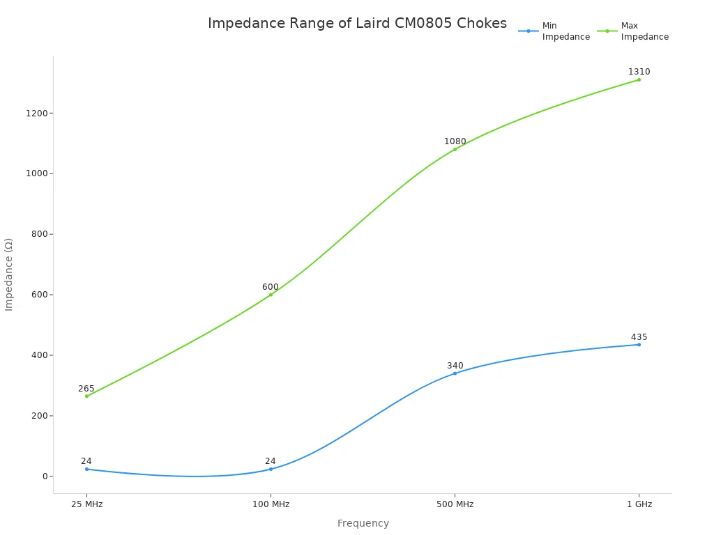
The frequency response of common mode chokes is critical for filtering high-frequency noise. Below the self-resonant frequency, the choke acts like an inductor and blocks more noise as frequency increases. Above this point, it loses effectiveness. Some chokes show better insertion loss in certain bands, which means they block more noise and improve device performance.
Key Design Considerations
Engineers must consider several factors when choosing common mode chokes:
- Impedance: Select a value that matches the noise level to be filtered.
- Frequency: Identify the range of noise frequencies present.
- Current: Make sure the choke can handle the maximum current.
- Signal Quality: Avoid signal loss or distortion.
- Size and Design: Larger chokes work better for low-frequency noise.
Other important points include temperature stability, core saturation, and thermal management. Larger chokes handle more current and dissipate heat better. The core material affects how well the choke works in different temperatures. Engineers should also avoid common mistakes, such as ignoring thermal limits or using the wrong core shape. Regulatory standards like FCC and CISPR require effective EMI suppression, so meeting these rules is essential for product approval.
Tip: Always test common mode chokes in real circuits. Use spectrum analyzers and follow EMC standards to ensure reliable EMI suppression.
Common Mode Chokes in Applications
Consumer Electronics
Manufacturers use common mode chokes in many consumer electronics to keep devices running smoothly. These components help smartphones, laptops, tablets, and smart home devices filter out unwanted noise. As devices become smaller and more complex, engineers need compact and efficient EMI filters. Common mode chokes fit this need because they work well in tight spaces and support high-frequency wireless features like Wi-Fi, Bluetooth, and 5G.
- Common mode chokes help prevent static or buzzing in audio devices.
- They improve signal clarity and keep devices working without interruptions.
- These chokes protect sensitive parts from electrical noise, making devices last longer.
- Surface-mount versions allow easy assembly in small gadgets.
- Manufacturers often combine them with other parts to save board space.
The rise of IoT and smart home products increases the demand for these chokes. They help devices meet strict EMC rules and keep up with new technology trends.
Automotive and Industrial
Automotive systems rely on common mode chokes to block noise and keep signals clean. High current chokes protect data lines, power supplies, and motor drives from EMI and RFI. Engineers select core materials and winding styles to match the needs of each vehicle system. Quality control and custom designs ensure that these chokes meet tough automotive standards.
In industrial automation, common mode chokes stop noise currents that can cause errors or downtime. They filter out interference from motors, transformers, and switching devices. This keeps signals clear for PLCs, sensors, and actuators. By using the right choke, factories avoid malfunctions and maintain steady production.
Note: Choosing the correct inductance and current rating is important for each application. This helps meet EMC standards and keeps equipment reliable.
Data and Communication
Data and communication systems use common mode chokes to protect signal quality. These chokes block high-frequency noise in USB, Ethernet, HDMI, and automotive networks. They allow data signals to pass with little loss, which keeps information clear and prevents errors.
| Application Area | Benefit of Common Mode Chokes |
|---|---|
| USB/Ethernet | Reduce EMI, keep data reliable |
| HDMI | Maintain video and audio quality |
| Automotive CAN/LIN | Prevent signal loss in vehicles |
High-speed data lines face many EMI challenges. Common mode chokes help by increasing the signal-to-noise ratio and stopping unwanted noise. This ensures that systems meet EMC standards and work without problems.
Common mode chokes play a vital role in blocking electromagnetic interference and keeping electronic systems reliable. Their benefits include strong noise suppression, improved signal integrity, and support for high-speed data and power systems.
| Key Aspect | Impact on Effectiveness |
|---|---|
| Inductance Value | Matches noise frequency for best results |
| Core Material | Ferrite suits high-frequency filtering |
| PCB Layout | Placement near noise sources boosts performance |
- Market growth in automotive, renewable energy, and smart devices shows rising demand for these components.
- New designs use better materials and smarter manufacturing for higher reliability.
Engineers should consider common mode chokes to meet future EMI challenges and ensure safe, efficient electronics.
FAQ
What is the difference between a common mode choke and a regular inductor?
A common mode choke blocks noise on both lines at once. A regular inductor only affects one line. Engineers use chokes for EMI suppression. Inductors help control current and voltage in circuits.
How does a common mode choke improve device safety?
A common mode choke stops unwanted signals from reaching sensitive parts. This action protects devices from malfunctions and failures. Safety improves because circuits stay stable and reliable.
Tip: Using common mode chokes helps devices pass safety and EMC tests.
Where should engineers place common mode chokes on a circuit board?
Engineers place common mode chokes close to connectors or entry points. This location blocks noise before it spreads. Placement near power or data lines increases effectiveness.
| Placement Area | Benefit |
|---|---|
| Near connector | Blocks incoming noise |
| On power line | Protects supply |
Can common mode chokes filter both high and low frequency noise?
Common mode chokes work best for high-frequency noise. Some designs also block low-frequency interference. Engineers select core materials and winding styles to match the noise type.
- Ferrite cores: High-frequency filtering
- Powdered iron: Low-frequency filtering