Choosing the Right Attenuator Made Simple
To choose the right attenuator for your application, you need to match key technical specifications. These include impedance, power rating, frequency range, connector type, and attenuation value. You can use the table below to see what each specification means:
| Specification | Description |
|---|---|
| Attenuation Value | How much signal reduction you get (for example, 10 dB means a 10 dB drop). |
| Frequency Range | The range of frequencies the attenuator supports. |
| Power Rating | The highest power level the attenuator can handle safely. |
| Connector Type | The type of connectors, such as SMA or BNC, for easy setup. |
| Impedance | Should match your system, often 50 Ω or 75 Ω, for best performance. |
You gain precise control over your signal by selecting the right attenuators. This process is straightforward if you focus on proper attenuator control and match your system’s needs.
Key Takeaways
- Identify your application needs before choosing an attenuator. Understand the type of signal and its power level to avoid costly mistakes.
- Always match the impedance of the attenuator to your system. This prevents signal loss and ensures optimal performance.
- Select an attenuator with a power rating at least 20-30% higher than your system's maximum power. This protects your equipment from damage.
- Choose the right type of attenuator based on your control needs. Fixed, variable, and programmable options offer different levels of flexibility.
- Use a checklist to compare specifications like attenuation value, frequency range, and connector type. This helps you make informed decisions.
Application Needs for Attenuators
Before you select an attenuator, you need to understand your application’s requirements. Each system has unique needs based on the type of signal, the power level, and the frequency range. These factors help you choose the right attenuator and avoid costly mistakes.
Signal Type
You should always start by identifying the type of signal in your system. Attenuators work with many signals, including analog, digital, RF, and microwave. The signal type affects which attenuator you need. For example, voltage variable attenuators work best for analog signals because they allow smooth changes in signal amplitude. Digital step attenuators are better for digital signals, as they provide set steps for adjusting amplitude. Knowing your signal type helps you pick an attenuator that gives you the right control and precision.
Attenuators serve many roles in different systems. Here is a quick look at where you might use them:
| Application Category | Description |
|---|---|
| Receivers | Attenuators reduce signal strength before it reaches sensitive circuit elements. |
| Transmitters | Used to manage output signal levels to prevent distortion or damage. |
| Test and Measurement Systems | Essential for achieving precise signal levels during testing processes. |
You will also find attenuators in communication systems, radar systems, and RF testing setups.
Power Level
You must check the power level your attenuator will handle. If you use an attenuator with too low a power rating, you risk damaging it or your equipment. A good rule is to choose an attenuator rated 20–30% higher than your system’s maximum power. This safety margin keeps your attenuator working well and protects your devices.
Frequency Range
The frequency range is another key factor. Attenuators have limits on the frequencies they can handle. To ensure reliable performance, select an attenuator with an upper frequency limit at least three times higher than your highest signal frequency. This rule of thumb helps you avoid signal loss or distortion. For example, if your system runs at 2 GHz, pick an attenuator rated for at least 6 GHz.
Tip: Always match the attenuator’s frequency range and power rating to your system’s needs for the best results.
By focusing on signal type, power level, and frequency range, you set a strong foundation for choosing the right attenuator. This approach helps you control signal amplitude, protect your equipment, and keep your system running smoothly.
Types of Attenuators
When you choose an rf attenuator, you need to know the main types. Each type works best for certain tasks. The table below shows how each type performs and where you might use it:
| Type | Performance Characteristics | Use Cases |
|---|---|---|
| Fixed Attenuator | Provides a constant level of attenuation | Simple signal reduction, protection |
| Step Attenuator | Offers precise control with pre-calibrated steps | Specific attenuation levels, automated testing |
| Variable Attenuator | Allows for manual adjustment of attenuation | Flexible signal control, lab and field testing |
| Programmable Attenuator | Computer-controlled for dynamic adjustments | Advanced rf testing, automation |
Fixed Attenuator
A fixed attenuator gives you a set amount of signal reduction. You cannot change its value. You use a fixed attenuator when you need simple, reliable control. Many rf systems use a fixed attenuator to protect sensitive parts from too much power. You also see them in test setups, communication systems, and defense electronics. Here are some common uses:
- Signal level adjustment
- Testing and measurement setups
- Communication systems
- Defense and aerospace electronics
- Protection of rf components
A fixed attenuator helps you keep your rf attenuator setup safe and stable.
Variable Attenuator
A variable attenuator lets you change the signal strength by hand or with a control. You can use a variable attenuator in labs or in the field. This type gives you flexibility when you need to adjust signal levels often. In satellite and aerospace systems, a variable attenuator helps you get the right signal for each test. Some designs have locks to stop unwanted changes. You can switch between manual and automated modes, which makes a variable attenuator great for many rf tasks.
Step Attenuator
A step attenuator lets you pick from set levels of attenuation. You use a step attenuator when you need precise control in steps, not smooth changes. Digital step attenuators work well in automated rf test setups. They give you high precision and help protect your hardware. You can use a step attenuator to meet standards, control signal strength, and keep your rf attenuator system safe. These are key in cellular base stations and other rf networks.
Programmable Attenuator
A programmable attenuator gives you the most control. You can set the attenuation value using a computer. This type of rf attenuator works well in advanced rf testing and automation. Programmable attenuators use TTL logic control, which lets you change settings quickly and accurately. You can use direct or latched parallel programming to set the attenuation. Some models let you pick the starting value when you power up. A programmable attenuator covers a wide range of attenuation values, making it perfect for dynamic rf environments.
Tip: Choose the right rf attenuator type based on your need for control, precision, and automation.
Choosing the Correct Attenuator
When you start choosing the correct attenuator, you need to focus on four main factors: attenuation value, impedance matching, power handling, and connector type. Each factor plays a key role in keeping your system safe and your signals clear.
Attenuation Value
Attenuation value tells you how much the attenuator will reduce your signal. You measure this in decibels (dB). Most commercial attenuators offer values from 3 dB to 40 dB. If you need more signal reduction, you can connect two or more attenuators in series. This method gives you flexibility and can save money, especially if you already have some attenuators on hand.
- Typical attenuation values for commercial RF attenuators:
- 3 dB
- 6 dB
- 10 dB
- 20 dB
- 30 dB
- 40 dB
Tip: If you need a special value, combine two attenuators to reach the exact attenuation you want.
Impedance Matching
Impedance matching is critical for signal quality. You must match the attenuator’s impedance to your system. Most RF systems use either 50 Ω or 75 Ω. If you mismatch the impedance, you risk signal reflections, power loss, and signal distortion. These problems can cause errors and reduce your system’s performance.
| Impedance | Common Applications |
|---|---|
| 50 Ω | RF/Microwave circuit designs, Test setups |
| 75 Ω | Microwave waveguides, Wireless links |
- Problems caused by mismatched impedance:
- Signal reflections that interfere with your signals
- Power loss, which lowers system sensitivity
- Signal distortion, leading to data errors
In RF systems, matching the source and load impedances helps you avoid these issues. A higher return loss means better impedance matching and better signal quality.
Power Handling
You must check the power rating of your attenuator. If you use an attenuator with a low power rating, it can overheat or fail. Always choose an attenuator rated at least 20–30% higher than your system’s maximum power. This safety margin protects your equipment.
| Material/Type | Power Rating (W) | Frequency Range |
|---|---|---|
| SMA Connectors | 250 | DC to 4 GHz |
| Type-N and TNC Connectors | 250 | DC to 3 GHz |
| SMA Terminations | 50 | Up to 18 GHz |
| Chip Terminations (BeO) | 15 | Microwave Frequencies |
| Chip Resistors (Alumina) | >100 | Microwave Frequencies |
| Waveguide Flanges | >1000 | High-Power Applications |
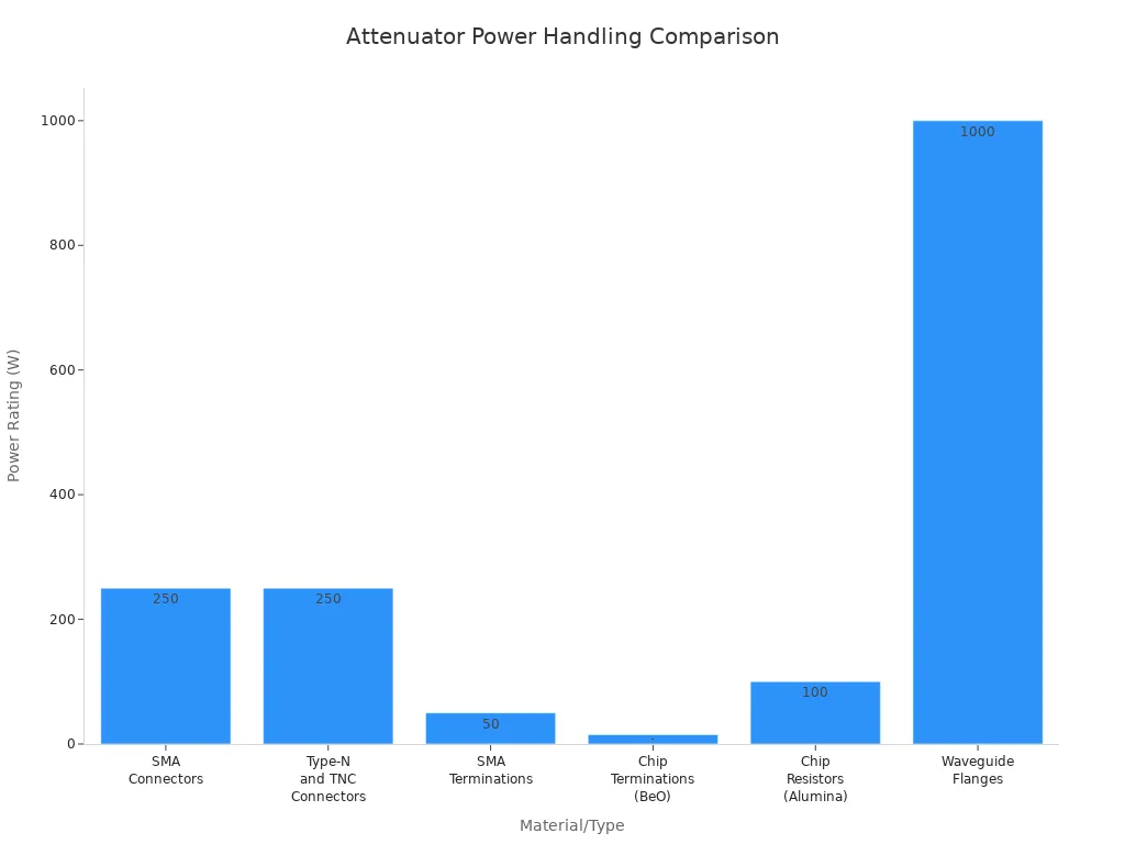
Note: High-power applications, such as waveguide flanges, need attenuators that can handle over 1000 watts.
Connector Type
Connector type affects both compatibility and performance. You must match the connector type and impedance to your system. For example, 50-ohm connectors are common in RF test equipment and communications gear. 75-ohm connectors are standard for video broadcasting and cable TV. Using the wrong connector can damage your equipment or cause signal loss.
| Connector Type | Impedance | Compatibility Issues |
|---|---|---|
| 50-ohm | 50 ohm | Incompatible with 75-ohm, can cause damage |
| 75-ohm | 75 ohm | Incompatible with 50-ohm, can cause echo loss |
- Mismatched connectors can lead to:
- Signal reflections
- Impedance mismatch
- Poor system performance
Tip: Always check both the connector type and impedance before you connect an attenuator.
If you need flexible control, consider a programmable attenuator. Programmable attenuators let you set the attenuation value using a computer or logic control. You can use programmable models for automated testing or dynamic RF environments. Some programmable attenuators also offer variable attenuation, which gives you even more control.
By focusing on these four factors, you make sure your attenuator fits your system. This approach helps you avoid common mistakes and keeps your signals strong and clear.
How to Choose a RF Attenuator
Step-by-Step Guide
You can follow a simple process when you want to choose a rf attenuator for your project. This guide helps you avoid mistakes and find the best match for your needs.
-
Define Your Application
Start by asking what you need the attenuator to do. Do you want to protect sensitive equipment, adjust signal levels, or automate testing? Knowing your goal helps you narrow down your options. -
Identify Signal Type and Frequency
Check if your system uses analog, digital, or RF signals. Write down the highest frequency your signal will reach. Always select an attenuator with a frequency range at least three times higher than your signal’s top frequency. -
Determine Power Handling Needs
Find out the maximum power your system will send through the attenuator. Pick a model that can handle at least 20–30% more than this value. This step keeps your equipment safe. -
Select the Right Impedance
Match the attenuator’s impedance to your system. Most RF systems use 50 Ω or 75 Ω. Matching impedance prevents signal loss and distortion. -
Choose the Connector Type
Look at the connectors on your cables and devices. Pick an attenuator with the same connector type and impedance. -
Pick the Attenuator Type
Decide if you need a fixed, variable, or programmable attenuator. Use the table below to compare your options:Type of Attenuator Description Fixed Attenuators Simple, reliable, used for level control or termination Variable Attenuators Allow manual or electronic adjustment during operation Programmable DSAs Used in automated test systems or reconfigurable designs -
Check Key Performance Specs
Review the specs for attenuation range, accuracy, power handling, and frequency response. Flat frequency response is important for broadband signals.Key Performance Specs Description Attenuation Range and Accuracy How precisely you can control the signal Power Handling Especially important in high-output systems Frequency Response Flatness matters in broadband applications
Tip: Write down your answers for each step. This checklist makes it easy to compare different attenuators.
Example Scenarios
You can see how to choose an rf attenuator by looking at real-world examples. These scenarios show how the guide works in practice.
Scenario 1: Lab Test Setup
You work in a lab and need to test a new RF amplifier. The amplifier operates at 1 GHz and outputs up to 10 watts. You want to reduce the signal before it reaches your test equipment.
- Step 1: Application: Protect test equipment.
- Step 2: Signal type: RF, Frequency: 1 GHz.
- Step 3: Power: 10 W. Choose an attenuator rated for at least 13 W.
- Step 4: Impedance: 50 Ω.
- Step 5: Connector: SMA.
- Step 6: Type: Fixed attenuator for simple, reliable control.
- Step 7: Specs: 10 dB attenuation, flat frequency response up to 3 GHz.
You select a 10 dB, 50 Ω, SMA fixed attenuator rated for 15 W and up to 3 GHz.
Scenario 2: Automated Test System
You design an automated test system for wireless devices. The system needs to change signal levels quickly during tests. The frequency range is 2–4 GHz, and the maximum power is 5 W.
- Step 1: Application: Automated signal level control.
- Step 2: Signal type: RF, Frequency: up to 4 GHz.
- Step 3: Power: 5 W. Choose an attenuator rated for at least 7 W.
- Step 4: Impedance: 50 Ω.
- Step 5: Connector: N-type.
- Step 6: Type: Programmable DSA for automation.
- Step 7: Specs: 0–30 dB range, 1 dB steps, flat response across 2–4 GHz.
You pick a programmable attenuator with 0–30 dB range, 1 dB steps, 50 Ω impedance, N-type connectors, and a 10 W rating.
Scenario 3: Field Adjustment
You need to adjust signal levels in a satellite communication link. The system runs at 6 GHz and uses low power.
- Step 1: Application: Field signal adjustment.
- Step 2: Signal type: RF, Frequency: 6 GHz.
- Step 3: Power: 1 W. Choose an attenuator rated for at least 1.3 W.
- Step 4: Impedance: 50 Ω.
- Step 5: Connector: SMA.
- Step 6: Type: Variable attenuator for manual adjustment.
- Step 7: Specs: 0–20 dB range, smooth adjustment, flat response up to 18 GHz.
You select a variable attenuator with 0–20 dB range, 50 Ω, SMA connectors, and a 2 W rating.
Note: You can use this guide for any RF application. Write down your requirements and compare products step by step.
Common Mistakes When Choosing Attenuators
When you select an attenuator for your RF system, you want to avoid common mistakes that can hurt performance or damage equipment. Many engineers and technicians make errors that seem small but can have big effects. Here are some frequent mistakes you should watch out for:
- You might not consider the specific needs of your application. Each system has unique requirements, so you need to match the attenuator to your setup.
- Sometimes, people overlook the importance of signal integrity. If you ignore key parameters, your signal can become distorted or weak.
- Failing to check attenuation value, accuracy, frequency range, and impedance can lead to poor results.
- Choosing an attenuator with an insufficient power rating can cause excessive heat. This may exceed the maximum temperature rating and create thermal management problems. The attenuator can get damaged, and you might see reflections or signal distortion. These issues can degrade your system’s performance.
- Mismatched impedance is another common mistake. If the attenuator’s impedance does not match your system, you risk signal loss and unwanted reflections.
- Picking the wrong frequency range can result in loss of signal quality. Your attenuator must support the full range of frequencies your system uses.
You can avoid these mistakes by following best practices. Always install attenuators at the receiving end to prevent signal overload. Make sure you orient the attenuator correctly to avoid signal loss or damage. Establish a secure connection to keep your signal strong. Check that the attenuator is compatible with your system for efficient performance. After installation, test your system and perform regular maintenance to catch problems early.
Tip: Careful selection and regular checks help you maintain signal integrity and protect your equipment.
You can choose the right attenuator by following these steps:
- Check the attenuation range and frequency compatibility.
- Match the impedance and power handling to your system.
- Review mechanical stability and control interfaces.
| Selection Criteria | Why It Matters |
|---|---|
| Attenuation Value | Controls signal strength |
| Frequency Range | Ensures proper operation |
| Impedance | Prevents signal loss |
| Power Handling | Protects your equipment |
Using a checklist helps you avoid mistakes and keeps your system safe. When you select the correct attenuator, you protect your devices and maintain signal integrity.
FAQ
What happens if you use an attenuator with the wrong impedance?
If you use the wrong impedance, your signal can reflect back. This causes signal loss and distortion. Always match the attenuator’s impedance to your system for the best performance.
Can you combine two attenuators to get a custom value?
Yes, you can connect two attenuators in series. Add their values to get the total attenuation. For example, a 6 dB and a 10 dB attenuator together give you 16 dB.
How do you know which connector type to choose?
Check the connectors on your cables and devices. Pick an attenuator with the same connector type and impedance. This ensures a secure fit and keeps your signal strong.
Do attenuators affect signal quality?
Attenuators reduce signal strength but should not distort the signal if you choose the right type. Always select an attenuator with a flat frequency response for your application.