Voltage in Series and Parallel Circuits What You Need to Know
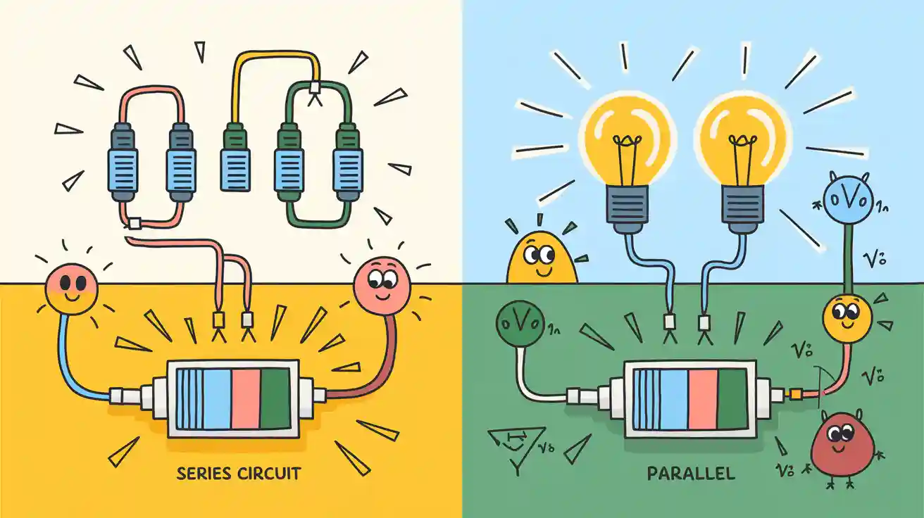
Voltage behaves differently in series and parallel circuits. In a series circuit, voltage splits between resistors, while in a parallel circuit, each branch receives the same voltage. Understanding the change in voltage series or parallel helps students design circuits that work correctly. Resistors play a key role in both types. Trusted resources like OpenStax Physics and Conceptual Physics explain these ideas clearly. Hands-on experiments with series and parallel circuits help students learn by seeing real results. Examples and formulas make these concepts easier to grasp.
Key Takeaways
- In series circuits, voltage splits among resistors while current stays the same through all components.
- In parallel circuits, each resistor gets the full voltage from the power source, but current divides among branches.
- Series circuits are useful when you need to divide voltage, but if one resistor fails, the whole circuit stops working.
- Parallel circuits keep voltage constant across all devices and allow them to work independently, making them more reliable.
- Knowing how voltage works in these circuits helps you design safe, effective systems and troubleshoot problems easily.
Change in Voltage Series or Parallel
Key Difference
The change in voltage series or parallel stands as one of the most important ideas in basic electronics. In a series circuit, the total voltage from the power source splits across each resistor. Each resistor receives only part of the total voltage, and the sum of these voltage drops equals the total voltage supplied. In contrast, a parallel circuit connects each resistor directly to the power source. Every resistor in parallel circuits receives the same voltage as the source, no matter how many resistors are present.
Tip: Series circuits act as voltage dividers, while parallel circuits keep the voltage the same across all branches.
Here is a simple table that shows how voltage behaves in both types of circuits:
| Circuit Type | Voltage Distribution Description |
|---|---|
| Series Circuit | The total voltage supplied by the source is divided among the components; the sum of voltage drops equals the total voltage. |
| Parallel Circuit | Each component experiences the same voltage as the source; voltage across all components is equal. |
In series, the current stays the same through every resistor. In parallel, the current splits between the branches, but the voltage across each branch remains constant. This difference in current and voltage behavior helps explain why the change in voltage series or parallel is so important for designing circuits.
- In series circuits:
- Voltage across each resistor differs.
- The total voltage equals the sum of the voltage drops.
- Current remains the same through all resistors.
- In parallel circuits:
- Voltage across each resistor is identical.
- The total voltage equals the voltage across each branch.
- Current divides among the branches.
Why It Matters
Understanding the change in voltage series or parallel helps students and engineers build circuits that work as intended. When someone connects resistors in series, each resistor gets only a part of the total voltage. For example, if three equal resistors are in series with a 16-volt source, each resistor receives about 5.33 volts. The current remains the same through all resistors, making it easy to predict how the circuit will behave.
In parallel circuits, every resistor gets the full voltage from the source. If a 16-volt battery connects to three resistors in parallel, each resistor receives the full 16 volts. The current, however, splits between the branches. This means that adding more branches in parallel circuits increases the total current drawn from the source, but the voltage across each branch does not change.
| Circuit Type | Voltage Behavior |
|---|---|
| Series Circuit | Voltage drop across each component adds up to the total applied voltage; voltage drop is proportional to resistance. |
| Parallel Circuit | Voltage drop across each component is the same and equal to the source voltage. |
The change in voltage series or parallel affects how devices work in real life. For example, string lights wired in series may dim if one bulb fails, because the voltage divides among all bulbs. In parallel, each bulb shines at full brightness, since each receives the full voltage. This knowledge helps people choose the right circuit type for their needs.
Note: Series circuits are useful when voltage division is needed, while parallel circuits are best when each device needs the same voltage.
Understanding how voltage and current behave in both series and parallel circuits allows students to predict circuit performance, troubleshoot problems, and design safe, effective systems.
Series Circuit Basics
Definition
A series circuit has only one path for current to flow. Every resistor in series shares the same current. This type of circuit connects each resistor end-to-end, so the current moves through each resistor one after another. The total resistance in a series circuit equals the sum of all the resistors. Schematic diagrams show this series connection with lines and symbols, making it easy to see how the circuit works. Wiring diagrams help people build real circuits by showing where to place each resistor and wire.
In a series circuit, the total voltage from the power source splits across all resistors. The sum of the potential drop across each resistor equals the total voltage supplied.
Resistors in Series
Resistors in series connect in a straight line, so the current through each resistor stays the same. People often use jumper wires, breadboards, or terminal strips to connect resistors in series. The total resistance increases as more resistors are added. The voltage divides among the resistors in series, and each resistor gets a share of the total voltage based on its resistance. The potential drop across each resistor depends on its value. Larger resistors in series have a bigger potential drop across each resistor. The voltage across the resistors adds up to the total voltage from the battery or power supply.
| Concept | Series Circuits Explanation |
|---|---|
| Total Resistance | Sum of all resistors in series connection |
| Current | Same current through each resistor |
| Voltage Division | Voltage divides among resistors in series, proportional to resistance |
| Potential Drop | Each resistor has a potential drop across each resistor, larger resistance means larger drop |
| Series Connection | End-to-end arrangement, only one path for current |
Example
Suppose a series circuit has three resistors in series: R1 = 12 Ω, R2 = 6 Ω, and R3 = 4 Ω. The total resistance equals 22 Ω. If the current through each resistor is 0.5 A, use ohm's law to find the potential drop across each resistor:
- V1 = 0.5 A × 12 Ω = 6.0 V
- V2 = 0.5 A × 6 Ω = 3.0 V
- V3 = 0.5 A × 4 Ω = 2.0 V
The sum of the potential drop across each resistor is 6.0 V + 3.0 V + 2.0 V = 11 V. The voltage across the resistors matches the total voltage supplied. Series circuits always follow this rule. When people calculate total resistance, they add up all the resistors in series. Mistakes can happen if someone mixes up series and parallel circuits or forgets to label current direction.
Tip: Always check the series connection and label each resistor to avoid errors in voltage calculations.
Parallel Circuit Basics
Definition
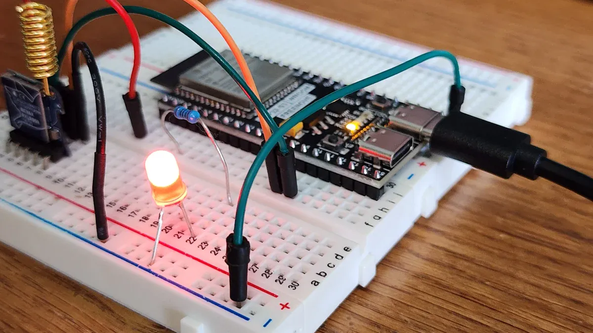
A parallel circuit gives each resistor its own branch. In this type of circuit, both ends of every resistor connect directly to the same two points. This setup creates multiple paths for current to flow. Each branch in a parallel circuit receives the same voltage as the power supply. The current divides at the branching points, with each path carrying its own share. Schematic diagrams show parallel circuits clearly, using symbols to represent each resistor and the way branches split and rejoin. This makes it easy to see how the parallel connection works.
- Resistors in parallel have both ends connected together.
- The voltage across each resistor in parallel circuits is always the same.
- Each branch provides a separate path for current.
- The total resistance in parallel circuits is less than the smallest resistor.
- Adding more branches lowers the total resistance and increases the total parallel circuit current.
- Parallel circuits allow devices to work independently.
Resistors in Parallel
Resistors in parallel share the same voltage, but the current through each resistor can differ. The amount of current through each resistor depends on its resistance. Lower resistance means more current flows through that branch. The total current in the circuit equals the sum of the current through each resistor. Parallel circuits make it possible to add or remove devices without changing the voltage across the others. This makes parallel circuits reliable and safe for many applications.
The formula for voltage across resistors in parallel is simple:
This means every resistor in parallel gets the full supply voltage. The total resistance for resistors in parallel is always less than the smallest resistor in the group. The formula for total resistance in a parallel connection is:
- 1/R_total = 1/R1 + 1/R2 + 1/R3 + ...
Example
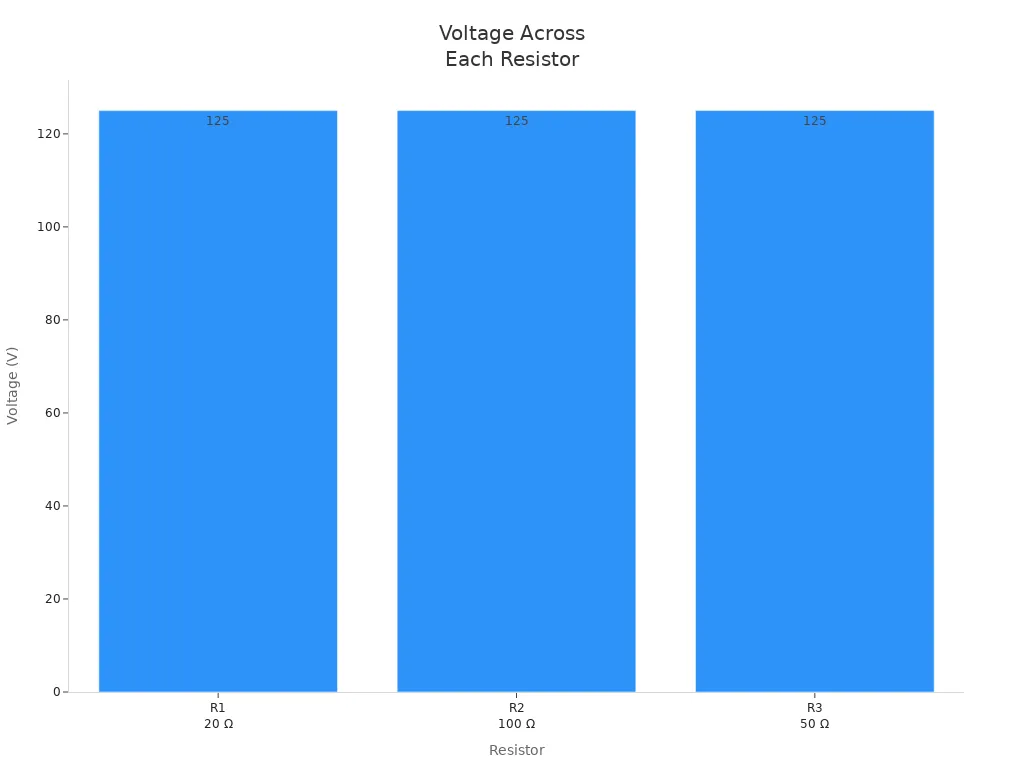
Consider a parallel circuit with three resistors in parallel: R1 = 20 Ω, R2 = 100 Ω, and R3 = 50 Ω. The power supply provides 125 V. The voltage across each resistor is 125 V, because parallel circuits keep the voltage the same for all branches. The current through each resistor is different:
| Parameter | Value / Calculation | Explanation |
|---|---|---|
| Resistors (R1, R2, R3) | 20 Ω, 100 Ω, 50 Ω | Given resistor values in parallel |
| Power supply voltage (V) | 125 V | Voltage supplied by battery |
| Equivalent resistance (R_T) | 1/R_T = 1/20 + 1/100 + 1/50 = 0.08 | Sum of reciprocals of resistances |
| R_T = 1 / 0.08 = 12.5 Ω | Equivalent resistance calculated | |
| Total current (I_T) | I_T = V / R_T = 125 V / 12.5 Ω = 10 A | Total parallel circuit current |
| Voltage across each resistor | V1 = V2 = V3 = 125 V | Voltage is the same across all parallel resistors |
| Current through R1 (I1) | I1 = V1 / R1 = 125 V / 20 Ω = 6.25 A | Ohm’s law applied to resistor 1 |
| Current through R2 (I2) | I2 = V2 / R2 = 125 V / 100 Ω = 1.25 A | Ohm’s law applied to resistor 2 |
| Current through R3 (I3) | I3 = V3 / R3 = 125 V / 50 Ω = 2.50 A | Ohm’s law applied to resistor 3 |
| Current sum verification | I_T = I1 + I2 + I3 = 6.25 + 1.25 + 2.50 = 10 A | Matches total current, confirming calculations |
Tip: In parallel circuits, adding more resistors in parallel always decreases the total resistance and increases the total parallel circuit current. Each resistor in parallel receives the same voltage, so devices work at full power.
Series vs. Parallel Comparison
Voltage Differences
Series circuits and parallel circuits show clear differences in how voltage and current behave. In a series circuit, all resistors connect in a single loop. The same current flows through each resistor, but the voltage divides among them. The total voltage from the power source splits across the resistors, with each resistor receiving a portion based on its resistance. If one resistor breaks, the entire circuit stops working.
Parallel circuits have multiple paths for current. Each resistor connects directly to the power source, so the voltage across every resistor stays the same. The current splits among the branches, depending on the resistance of each path. If one branch fails, the other branches continue to work. This makes parallel circuits more reliable for systems that need constant voltage.
| Aspect | Series Circuit | Parallel Circuit |
|---|---|---|
| Current behavior | Same current flows through all resistors | Current divides among branches based on resistance |
| Voltage behavior | Voltage divides among resistors | Same voltage across each resistor |
| Circuit paths | Single path for current flow | Multiple independent paths for current |
| Effect of failure | One open resistor stops entire current flow | One open branch does not stop current in other branches |
Practical Implications
Engineers and students choose series or parallel circuits based on voltage needs. Series circuits work best when voltage division is important. For example, voltage divider applications, analog biasing, and signal conditioning use series circuits to control voltage levels. Connecting batteries in series increases the total voltage available.
Parallel circuits are ideal for situations where each device needs the same voltage. Household lighting, electrical outlets, and vehicle systems use parallel circuits to ensure every device receives full voltage. If one device fails, others keep working. Parallel circuits also make it easy to add or remove devices without affecting the rest of the system.
Combinations of series and parallel circuits appear in many real-world designs. These combinations allow engineers to balance voltage, current, and resistance for specific needs.
Tip: Use series circuits for controlled voltage division. Choose parallel circuits for consistent voltage and reliable operation.
Quick Reference Table
| Feature | Series Circuit | Parallel Circuit |
|---|---|---|
| Voltage | Divides among resistors; total voltage is sum | Same across all resistors; equals source voltage |
| Current | Same through all resistors | Divides among branches; total is sum of branch currents |
| Resistance | Sum of all resistors | Less than smallest resistor; calculated by reciprocals |
| Failure Behavior | One resistor failure breaks circuit | One branch failure does not affect others |
| Best For | Voltage dividers, reference voltages | Home lighting, outlets, vehicle circuits |
| Expansion | Difficult; affects voltage division | Easy; add devices without changing voltage |
| Combinations | Used for special voltage and current needs | Used for reliability and constant voltage |
Combinations of series and parallel circuits help designers create systems with both controlled voltage division and reliable operation. Understanding these differences allows students to build circuits that work safely and efficiently.
Understanding voltage in series and parallel circuits helps students and engineers design safe, reliable systems. In series circuits, voltage divides among components, making voltage dividers useful for signal adjustment, reference generation, and transistor biasing. Parallel circuits keep voltage constant across all branches, supporting devices that need the same voltage, such as home lighting or digital circuits.
| Feature | Series Circuits | Parallel Circuits |
|---|---|---|
| Voltage Behavior | Voltage divides among components | Voltage remains constant |
Knowing how voltage works improves troubleshooting and protects sensitive devices. Students should always follow safety guidelines when working with circuits. Applying these voltage concepts in real projects builds strong problem-solving skills.
FAQ
What happens to voltage if one resistor fails in a series circuit?
If one resistor fails in a series circuit, the current stops. All devices lose power. The voltage does not reach the other resistors. Series circuits need every part to work for the circuit to function.
Does adding more resistors in parallel change the voltage across each resistor?
Adding more resistors in parallel does not change the voltage across each resistor. Each branch still receives the full supply voltage. The total current increases, but the voltage stays the same for every resistor.
How do you calculate total resistance in a parallel circuit?
Use this formula for total resistance in parallel:
1/R_total = 1/R1 + 1/R2 + 1/R3 + ...The total resistance is always less than the smallest resistor in the group.
Why do household lights use parallel circuits instead of series circuits?
Household lights use parallel circuits because each light receives the same voltage. If one bulb burns out, the others stay lit. Parallel circuits provide reliable and consistent power for every device.