Understanding the effects of connecting capacitors in parallel and series
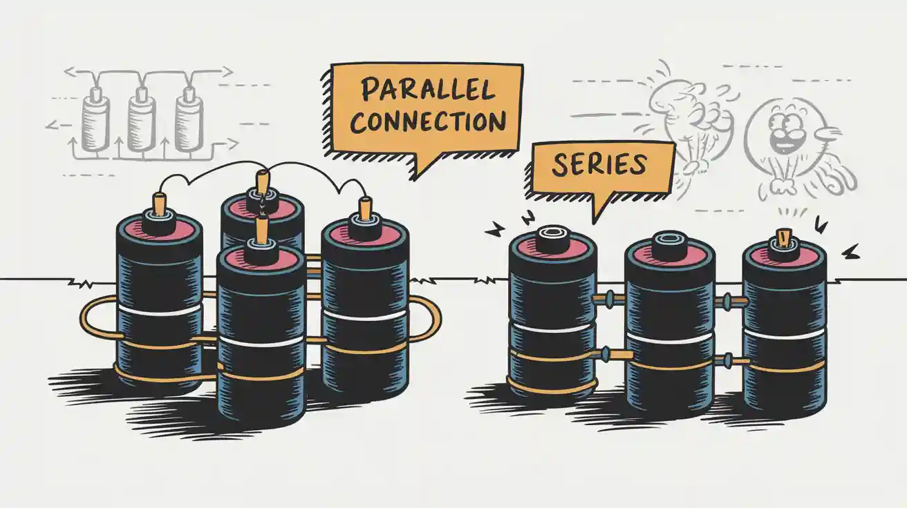
When you connect capacitors in parallel vs series, you change how they store charge and share voltage. In parallel, each capacitor gets the same voltage and their capacitances add up, which boosts your total energy storage. In series, capacitors share the same charge but split the voltage, and the total capacitance drops below the smallest capacitor. See how the total capacitance changes:
| Configuration | Formula | Example Calculation |
|---|---|---|
| Series | $C_s = \frac{1}{\frac{1}{C_1} + \frac{1}{C_2} + \frac{1}{C_3}}$ | $C_1 = 2 \mu F$, $C_2 = 3 \mu F$, $C_3 = 6 \mu F$: $C_s = 1 \mu F$ |
| Parallel | $C_p = C_1 + C_2 + C_3$ | $C_1 = 1.0 \mu F$, $C_2 = 5.0 \mu F$, $C_3 = 8.0 \mu F$: $C_p = 14.0 \mu F$ |
You need to understand these differences because the right setup helps you balance space, voltage, and performance in your circuits.
Key Takeaways
- Connecting capacitors in parallel increases total capacitance, allowing for greater energy storage in your circuit.
- In series, the total capacitance decreases and is always less than the smallest capacitor, which helps control charge storage.
- Use capacitors in parallel for stable voltage and higher current handling, especially in power supplies and audio equipment.
- Choose series connections when you need to increase voltage ratings and ensure balanced charge distribution across capacitors.
- Always match capacitor values in series to avoid uneven voltage and check voltage ratings to prevent circuit damage.
Capacitors in Parallel
Capacitance Increase
When you connect capacitors in parallel, you create a system where each capacitor works together to store more charge. You will notice that the total capacitance in parallel is much higher than the capacitance of any single capacitor. The formula for total capacitance in parallel is simple: you add up the capacitances of each capacitor. For example, if you have capacitors with values of 12 µF, 20 µF, and 30 µF, the total capacitance becomes 62 µF. This shows how capacitances add in parallel.
You can use this method to increase the total capacitance in your circuit. The equivalent capacitor in parallel acts like a bigger storage tank for electrical charge. You get more energy storage without needing a single large capacitor. The total capacitance in parallel lets you design circuits that handle more charge and work better for applications like power supplies or audio equipment.
Tip: If you need more charge storage, try adding capacitors in parallel. This increases the total capacitance and helps your circuit perform better.
Here are some practical benefits you get when you increase total capacitance by connecting capacitors in parallel:
- You store more electrical charge in your circuit.
- You reduce equivalent series resistance, which means your circuit charges and discharges more efficiently.
- You improve current handling because the current spreads across multiple capacitors, lowering heat and stress.
Voltage Across Plates
When you use capacitors in parallel, each capacitor experiences the same voltage across its plates. The voltage across every equivalent capacitor matches the voltage supplied to the whole parallel arrangement. This means you do not need to worry about different voltages for each capacitor. The total capacitance in parallel does not affect the voltage across each capacitor.
Capacitors connected in parallel share the same voltage, but each stores a different amount of charge based on its capacitance. The total charge in the system equals the sum of the charges on each capacitor. You can use the relationship: Q_total = C_A * V + C_B * V + C_C * V, where C_A, C_B, and C_C are the capacitances of the individual capacitors.
You can rely on capacitors in parallel to keep voltage steady while boosting total capacitance. This makes them useful for circuits that need stable voltage and extra charge storage.
Capacitors in Series
Capacitance Decrease
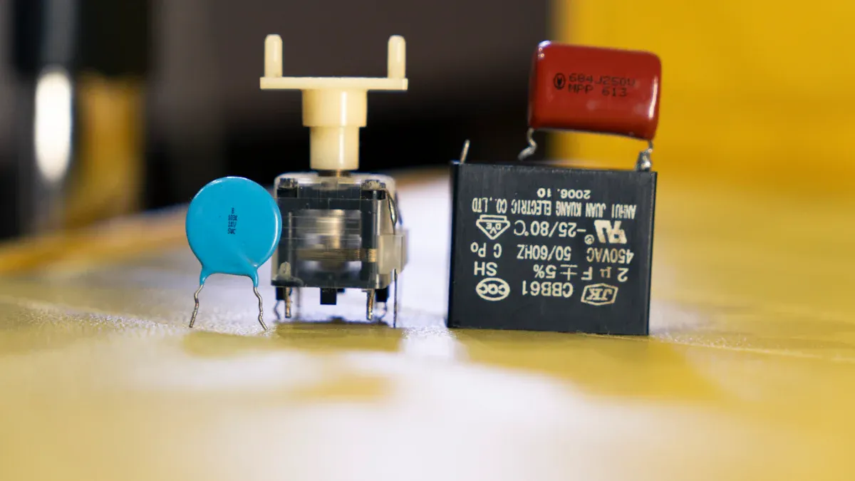
When you connect capacitors in series, you create a path where the same charge flows through each capacitor. You will notice that the total capacitance in series drops below the smallest individual capacitor in the group. This happens because the formula for total capacitance in series uses reciprocals:
The total capacitance for capacitors in series is given by the formula: ( \frac{1}{C_{\text{S}}}=\frac{1}{C_{1}}+\frac{1}{C_{2}}+\frac{1}{C_{3}}+\dots )
Let’s look at why capacitances diminish in series. When you add more capacitors in series, the total capacitance gets even smaller. For example, if you connect a 0.1μF, 0.2μF, and 0.5μF capacitor in series, the total capacitance in series will be less than 0.1μF. This happens every time because of the reciprocal calculation.
- The total capacitance of capacitors connected in series is always less than the smallest individual capacitor in the series.
- This is due to the reciprocal nature of the capacitance calculation in series configurations.
- For example, if the smallest capacitor in the series is 0.1μF, the total capacitance will be less than this value.
You use capacitors in series when you want to lower the total capacitance in your circuit. This setup helps you control the amount of charge stored and can be useful in timing circuits or filters.
Voltage Distribution
When you connect capacitors in series, the total voltage across all capacitors equals the voltage from your power source. Each capacitor gets a different voltage, and the voltage across each one depends on its capacitance. The smaller the capacitance, the higher the voltage across that capacitor.
- The total voltage across series capacitors equals the source voltage.
- The voltage across each capacitor is inversely proportional to its capacitance.
- Current flow is the same through all capacitors in series, leading to equal charge change across them.
You will see that the charge stored on each capacitor in series is the same. This happens because there is only one path for current. The relationship between charge, capacitance, and voltage is simple: Q = C × V. In series, the charge stays the same, but the voltage splits up.
| Concept | Explanation |
|---|---|
| Charge in Series Capacitors | The charge stored on each capacitor in series is the same and is less than that of a single capacitor connected to the same voltage source. |
| Equivalent Capacitance | The equivalent capacitance of two equal capacitors in series is half the capacitance of each. |
| Charge Calculation | The charge on the equivalent series capacitance is the same as the charge on each series capacitor, calculated as ( \frac{C}{2}V ). |
You may want to use capacitors in series to increase the total voltage rating. When you connect capacitors in series, the voltage ratings add up. This lets your circuit handle higher voltages without damaging the capacitors. You also get balanced charge distribution and improved reliability. If one capacitor fails, the others can still work.
Tip: Use capacitors in series when you need a higher voltage rating and want to keep the charge the same across all capacitors.
Capacitors in Parallel vs Series
Key Differences
When you compare capacitors in parallel vs series, you see big differences in how they work. The way you connect capacitors changes the total capacitance, voltage, and charge behavior in your circuit. In a parallel setup, you add the capacitance values together. This means the total capacitance increases, and you can store more charge at the same voltage. In a series setup, the total capacitance drops below the smallest capacitor in the group. The charge must pass through each capacitor, making it harder to store charge.
You can see these differences in the table below:
| Connection Type | Voltage Behavior | Charge Behavior |
|---|---|---|
| Parallel | Same voltage across all capacitors; limited by the lowest voltage rating | Total charge is the sum of charges on each capacitor |
| Series | Voltage divides among capacitors; total voltage is the sum of each | Same charge across all capacitors |
The rules for adding capacitors in parallel vs series are not the same as for resistors. In parallel, capacitors increase total capacitance, but resistors decrease total resistance. In series, capacitors decrease total capacitance, but resistors increase total resistance. This difference is important when you design circuits.
| Configuration | Capacitors | Resistors |
|---|---|---|
| Series | Total capacitance decreases; 1/Ctotal = 1/C1 + 1/C2 + ... | Total resistance increases; Rtotal = R1 + R2 + ... |
| Parallel | Total capacitance increases; Ctotal = C1 + C2 + ... | Total resistance decreases; 1/Rtotal = 1/R1 + 1/R2 + ... |
You should always check the voltage and charge behavior when you choose between capacitors in parallel vs series. In parallel, every capacitor gets the same voltage, but the total charge is higher. In series, the charge stays the same, but the voltage splits up. This affects how much energy your circuit can store and how it handles power.
Note: In a parallel connection, you get more total capacitance and better energy storage. In a series connection, you get a higher voltage rating but less total capacitance.
Application Scenarios
You need to pick the right configuration for your project. The choice between capacitors in parallel vs series depends on what your circuit needs.
Use capacitors in parallel when:
- You want to increase total capacitance for more energy storage.
- You need to keep the voltage the same across all capacitors.
- Your circuit needs to handle higher current, like in power supplies or audio equipment.
- You want to reduce equivalent series resistance and improve efficiency.
Use capacitors in series when:
- You need to increase the total voltage rating of your circuit.
- You want to balance charge across all capacitors.
- You work with high-voltage power supplies, signal filtering, or pulse circuits.
- You want to protect sensitive components by blocking certain frequencies.
Engineers often choose capacitors in parallel vs series based on voltage needs, reliability, and current requirements. For higher voltage, you use series connections. For higher total capacitance, you use parallel connections. Parallel circuits are more reliable because if one capacitor fails, the others keep working. Series circuits need careful matching of capacitor values to keep voltage balanced. You must also watch for leakage currents, which can cause uneven voltage and damage.
Here are some important factors to consider:
- Series configurations help when you need higher voltage handling and better voltage distribution.
- Parallel configurations are best for higher total capacitance and energy storage.
- In high-frequency circuits, parallel capacitors help keep AC impedance low, but if one fails, the others must handle more voltage.
- In series, unequal voltage sharing can damage capacitors if you do not match them well.
| Configuration | Advantages | Disadvantages |
|---|---|---|
| Series | Increases working voltage, manages voltage distribution | Reduces capacitance, sensitive to variations |
| Parallel | Increases total capacitance, better energy storage | Risk of failure if one capacitor fails, all share voltage |
Tip: Always check the voltage ratings and match capacitor values in series to avoid uneven voltage. In parallel, make sure each capacitor can handle the full voltage of the circuit.
The physical layout of your circuit board also matters. Good placement of capacitors reduces noise and keeps your circuit stable. Using multiple parallel capacitors helps maintain low AC impedance, which is important for high-speed circuits.
When you choose between capacitors in parallel vs series, think about total capacitance, voltage needs, reliability, and the specific job your circuit must do. This helps you get the best performance and keeps your electronics safe.
You can see the main differences between parallel and series connections in this table:
| Connection Type | Definition |
|---|---|
| Series | Components share one common node with no other component. |
| Parallel | Components share two common nodes. |
When you choose a configuration for capacitors, keep these tips in mind:
- Review the dissipation factor for better efficiency.
- Watch for DC bias effects on capacitance.
- Check capacitor tolerance for your application.
- Pick polarized or non-polarized capacitors as needed.
Always consider both capacitance and voltage ratings. Using the wrong setup can cause overheating, circuit failure, or even safety hazards.
FAQ
What happens if you mix different capacitor values in parallel?
You add the capacitance values together. The total capacitance increases. Each capacitor gets the same voltage. You can use different values to reach the exact capacitance you need.
Can you connect capacitors in series to handle higher voltage?
Yes, you can. The voltage rating adds up. For example, two 50V capacitors in series can handle 100V. Make sure each capacitor shares the voltage safely.
Tip: Always check the voltage ratings before connecting capacitors in series.
Why does total capacitance decrease in series?
The charge must pass through each capacitor. The formula uses reciprocals, so the total capacitance drops below the smallest value. You store less charge in series than in parallel.
Is it safe to mix old and new capacitors?
You should avoid mixing old and new capacitors. Old capacitors may fail faster. This can cause uneven voltage or damage your circuit. Use capacitors with similar age and ratings for best results.
| Capacitor Age | Risk Level |
|---|---|
| New | Low |
| Old | High |