From Millivolts to Volts A Practical LM358 Amplifier Tutorial
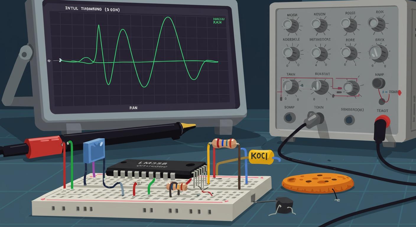
The lm358 is a versatile and beginner-friendly op-amp. This tutorial guides you in building a simple non-inverting amplifier circuit. You will use the popular lm358 to boost a small DC voltage from millivolts to volts.
This simple circuit is a key building block. Understanding it is a foundational step for anyone interested in electronics, from consumer gadgets to advanced scientific instruments.
Key Takeaways
- The LM358 is a simple chip. It helps you make small voltages bigger. It works with one power source.
- You can build a non-inverting amplifier. This circuit makes a small input voltage much larger. It does not change the signal's direction.
- Resistors control how much the signal grows. You use two resistors to set the amplifier's gain. This makes the output stable.
- Building this circuit teaches you about electronics. You can use this skill for audio projects or with sensors. It is a basic step for many electronic devices.
ESSENTIAL COMPONENTS
Before you start building, you need to gather a few key parts. This section introduces the main component, the LM358, and explains the basic theory behind our circuit.
THE LM358 OP-AMP
The heart of our project is the LM358 integrated circuit (IC). It is a popular dual operational amplifier. This means a single chip contains two independent op-amps. The lm358 is great for beginners because it works well with a single power supply. You do not need a complicated positive and negative supply.
You can find this versatile op-amp in many devices. It is used for audio amplification in speakers and for signal amplification with sensors. Industries use the lm358 in automation and control systems. Its reliability makes it a go-to choice for many electronics projects.
REQUIRED PARTS LIST
You will need the following components to build your amplifier circuit. Having everything ready will make the assembly process smooth and easy.
- Integrated Circuit: 1 x LM358 Dual Operational Amplifier
- Resistors (1/4 Watt):
- 1 x 1kΩ (Ri)
- 1 x 10kΩ (Rf)
- Power Source: 1 x 9V Battery or a 5V-12V DC power supply
- Tools & Supplies:
- 1 x Solderless Breadboard
- Jumper Wires
- 1 x Digital Multimeter (for testing)
NON-INVERTING AMPLIFIER BASICS
You are building a non-inverting amplifier. This type of circuit boosts an input voltage without flipping its polarity. A positive input voltage results in a larger positive output voltage. The op-amp achieves this using a concept called negative feedback.
The circuit uses two resistors to "feed back" a small portion of the output voltage to one of the inputs. This feedback loop controls how much the op-amp amplifies the signal. It ensures the output is stable and predictable. This simple circuit design is fundamental to analog electronics.
THE AMPLIFIER SCHEMATIC
Now you will look at the blueprint for your project. This section provides the circuit diagram and explains how each part works together to amplify your signal.
CIRCUIT DIAGRAM OVERVIEW
Below is the circuit diagram for your non-inverting amplifier. This visual guide shows you how to connect every component. The input signal goes into the non-inverting pin (IN+), and the amplified signal comes from the output pin (OUT). The two resistors, Ri and Rf, form the crucial feedback loop. This simple circuit explanation helps you understand the signal's path.
[Image Placeholder: A clean and clearly labeled schematic of the LM358 non-inverting amplifier circuit with a 9V supply, 1kΩ Ri, and 10kΩ Rf.]
GAIN AND FEEDBACK
The amount your signal gets boosted is called the gain. You control this using your two resistors, Rf and Ri. The formula is simple:
Gain = 1 + (Rf / Ri)
With a 10kΩ feedback resistor (Rf) and a 1kΩ input resistor (Ri), your calculation is 1 + (10000 / 1000) = 11. This means the circuit will make your input voltage 11 times larger. The feedback loop makes the op-amp's performance stable and predictable. It constantly adjusts the output to keep the voltage at the two input pins nearly identical, preventing the output from becoming unstable.
THE OPERATIONAL AMPLIFIER PINOUT
The LM358 operational amplifier chip has 8 pins. For this project, you only need to use a few of them. Here are the essential pins for one of the two amplifiers inside the chip:
- Pin 8 (VCC): You connect this to your positive power source (+9V).
- Pin 4 (GND): You connect this to the ground of your power source.
- Pin 3 (IN+): The non-inverting input, where you apply your small DC voltage.
- Pin 2 (IN-): The inverting input, which is part of the feedback loop.
- Pin 1 (OUT): The output, where you will measure the amplified voltage.
SINGLE-SUPPLY POWER CONNECTION
A great feature of the lm358 is its ability to run from a single power supply. You do not need separate positive and negative voltages. This simplifies your circuit and makes it perfect for battery-powered devices. Using a single 9V battery or a 5V source reduces cost and complexity. This efficiency is a key reason the LM358 is so popular in portable electronics.
BREADBOARD ASSEMBLY GUIDE
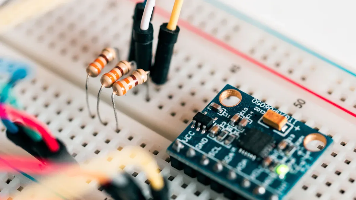
It is time to bring your schematic to life. This guide will walk you through each step of building the amplifier circuit on your breadboard. Follow the instructions carefully for a successful build.
PLACING THE IC
Your first step is to place the LM358 IC correctly. The orientation of the chip is very important.
- Find the Notch: Look for a small semi-circular notch at one end of the IC. Some chips may have a small dot in one corner instead. This mark shows you where pin 1 is.
- Position the IC: Carefully press the LM358 into the breadboard so it sits across the central channel.
- Insert the LM358 with the notch facing to the left.
- The pins on one side should be in one group of rows, and the pins on the other side should be in another.
Handle with Care! ICs are sensitive. Integrated circuits like the LM358 can be damaged by static electricity from your body. Before you touch the IC, ground yourself by touching a large metal object, like a table leg or your computer case. This simple action protects your components.
WIRING THE RESISTORS
Next, you will add the two resistors that create the feedback loop. These parts control the gain of your amplifier.
- Connect the Input Resistor (Ri - 1kΩ): Take your 1kΩ resistor. Insert one end into the same row as Pin 2 (the inverting input). Connect the other end to a ground rail on your breadboard.
- Connect the Feedback Resistor (Rf - 10kΩ): Take your 10kΩ resistor. Insert one end into the row for Pin 2. Connect the other end to the row for Pin 1 (the output). This connection "feeds back" part of the output signal to the input, which is essential for controlling the amplification.
A common mistake is swapping the feedback resistor with a load resistor or wiring the circuit like an inverting amplifier. Double-check that your resistors connect Pin 2 to ground (Ri) and Pin 2 to Pin 1 (Rf).
CONNECTING I/O PINS
Now you will add wires for your input signal and the final output. These are the points where the signal enters and leaves your amplifier circuit.
- Input Wire: Use a jumper wire to connect to Pin 3 (the non-inverting input). This is where you will apply the small voltage you want to amplify. Let the other end of this wire be free for now.
- Output Wire: Use another jumper wire to connect to Pin 1 (the output). This is where you will measure the amplified voltage. Let its other end be free as well.
CONNECTING POWER
The final assembly step is to power your circuit. Always connect power last to avoid damaging components.
- Connect VCC: Use a jumper wire to connect Pin 8 of the LM358 to the positive (+) power rail of your breadboard.
- Connect GND: Use another jumper wire to connect Pin 4 of the LM358 to the ground (-) power rail.
- Add a Decoupling Capacitor (Optional but Recommended): For better stability, connect a 100nF ceramic capacitor between Pin 8 (VCC) and Pin 4 (GND). Place it close to the IC. This small part helps filter out noise from the power supply, making your amplifier perform more reliably.
- Connect the Power Source: Now, connect your 9V battery or DC power supply to the power rails. The positive wire goes to the positive rail, and the negative wire goes to the ground rail.
Safety First! ⚡ Before you connect the battery, double-check all your connections. Make sure the positive and negative power wires are not touching and are connected to the correct rails. Using the wrong voltage or reversing the polarity can permanently damage your LM358.
TESTING AND APPLICATIONS
With your circuit assembled, you are ready for the most exciting part: testing. This section guides you through powering up your circuit, measuring its performance, and exploring what you can do next.
APPLYING A TEST VOLTAGE
You need a small input voltage to amplify. A simple way to create one is with a voltage divider.
- Grab two extra resistors (e.g., 10kΩ and 1kΩ).
- Connect them in series between your positive power rail and ground.
- The point between these two resistors will have a small, stable voltage. Connect your input wire (from Pin 3) to this point.
Measure Your Input First! 🔬 Before you test the output, use your multimeter to measure the exact voltage at Pin 3. This is your input voltage (Vi). Write this number down. For example, with a 9V supply and a 10kΩ/1kΩ divider, your input should be around 0.8V.
MEASURING THE OUTPUT
Now you will see your circuit in action. It is time to measure the amplified voltage.
- Set your multimeter to measure DC voltage.
- Connect the black probe of your multimeter to the ground rail.
- Carefully touch the red probe to the output wire connected to Pin 1.
- The multimeter will display the amplified output voltage (Vo).
VERIFYING THE GAIN
Does your result match the theory? You can verify the circuit's performance with a simple calculation. The output voltage (Vo) is determined by your input voltage (Vi) and the resistor values.
Expected Vo = Vi * (1 + Rf / Ri)
For an input of 0.8V and our chosen resistors, the math is 0.8V * (1 + 10000Ω / 1000Ω) = 8.8V. Your measured output should be very close to this value. This confirms your circuit's gain is working as designed. The op-amp works by adjusting its output to keep the voltages at the inverting and non-inverting inputs almost identical.
BEYOND THE BASICS
You have successfully built a foundational analog circuit. Now you can apply this knowledge to more exciting projects.
- Build a Simple Audio Amplifier: You can use this circuit as a pre-amplifier for an audio signal. Connect the output to a transistor like a BD139 or D882 to drive a small speaker.
- Interface with Sensors: Many sensors, like thermocouples, produce very small voltage changes. You can use this circuit to amplify their signals to a level a microcontroller can read.
- Create Filters and Oscillators: You can add capacitors to your design to create filters that block unwanted noise. You can also configure the op-amp to build an oscillator that generates a stable frequency signal.
Congratulations on building a functional op-amp circuit! You successfully took a small signal and amplified it using basic components. This project is more than just a simple electronics exercise.
Your new skill is a gateway to high-demand fields. Industries from IoT and medical electronics to automotive systems need experts in analog design. Keep exploring by building an audio pre-amplifier or a sensor interface. Your journey from millivolts to volts has just begun! 🚀
FAQ
Why is my output voltage not what I expected?
Your output might be incorrect due to a few reasons. First, double-check your resistor values. Ensure you used the correct Rf and Ri resistors. Also, confirm all your wires connect to the correct pins on the LM358 and the breadboard rails.
Can I get a negative voltage from this circuit?
No, this circuit cannot produce a negative voltage. You are using a single positive power supply. The output voltage can only swing between ground (0V) and a level slightly below your positive supply voltage (VCC).
What happens if I use a 5V power supply?
Your circuit will still work, but your maximum output voltage will be lower. The op-amp's output cannot go higher than its power supply voltage. With a 5V supply, your amplified output will be "clipped" or limited to just under 5V.
💡 Remember the Gain Formula! If your gain calculation
Vi * (1 + Rf / Ri)results in a voltage higher than your supply, the output will simply max out near the supply voltage.
Why use an op-amp instead of just a transistor?
Op-amps make amplifier design much simpler and more predictable. The gain is set easily with two resistors. A single transistor amplifier requires more complex calculations for biasing and is more sensitive to component variations. Op-amps give you reliable results with less effort.