Build Your Own LM317 Variable Power Supply A Step-by-Step Guide
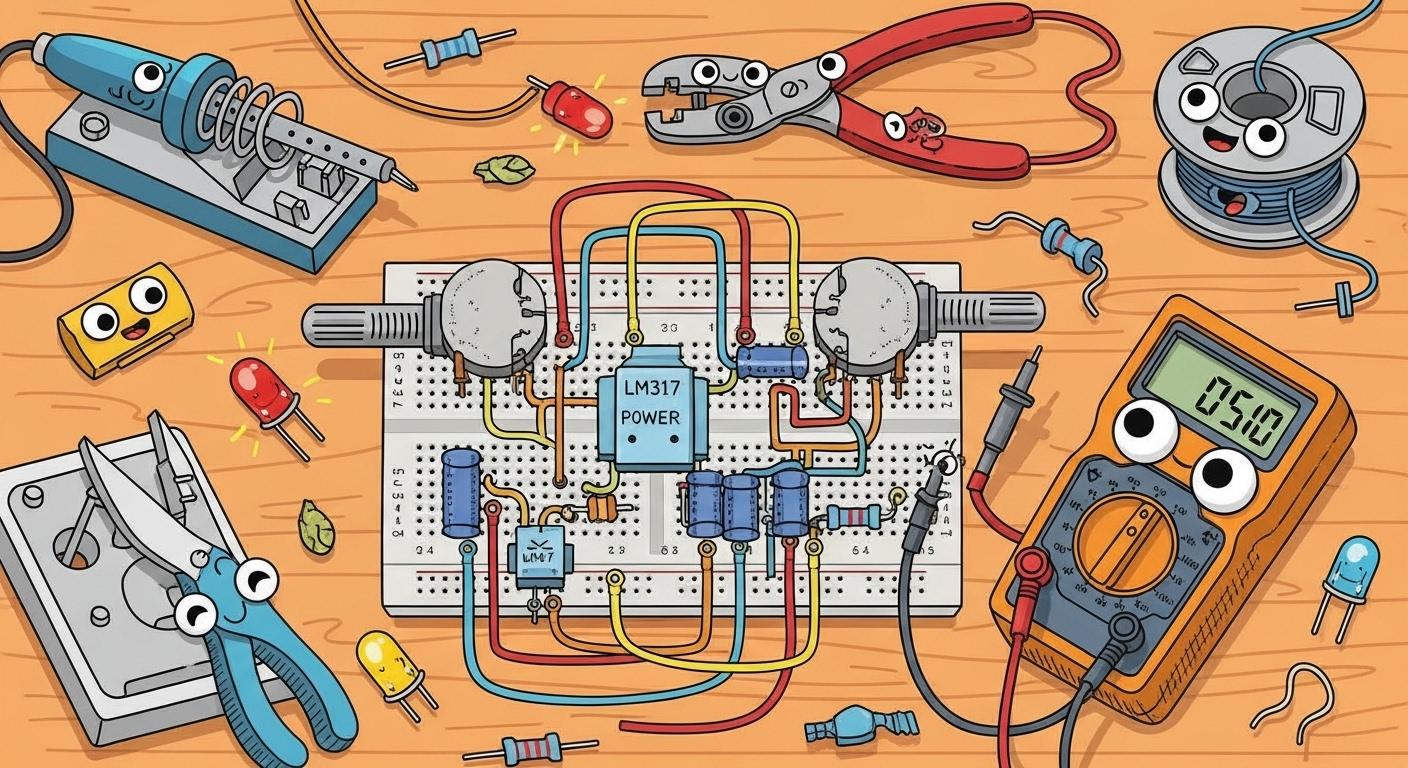
You can build your own adjustable DC power supply, a perfect tool for your electronics projects. This project uses the common lm317 to create a variable voltage output. You will soon have a basic lab bench power supply perfect for many electronics needs. The lm317 makes adjusting the voltage simple, giving you great power control.
Project Goal: Create a simple, adjustable power supply with a voltage range of 1.25V to 30V using the LM317 regulator. No advanced skill is required!
Key Takeaways
The LM317 chip is the main part of your power supply. It helps change a higher input voltage into a steady, adjustable output voltage.
You use two resistors, R1 and R2, to set the output voltage. R2 is a knob you turn to change the voltage.
Capacitors make the power smooth and steady. You must put them in the right way, or they will not work.
Always check your wires before you turn on the power. Use a multimeter to test the voltage and make sure it changes when you turn the knob.
The LM317 can get hot. If you use it for big projects, you need a metal heatsink to keep it cool.
Understanding the LM317 Circuit
Before you start building, it helps to know how your power supply works. The magic behind this project is the LM317, a type of linear voltage regulator. A linear regulator acts like a smart valve for electricity. It constantly adjusts its internal resistance to keep the output voltage steady, even if the input power fluctuates.
How the Regulator Works
There are two main types of linear regulators. The LM317 is a series regulator, which is very common and efficient. It places a variable resistance between your input power and the circuit's output.
The LM317 has a special feature inside. It generates a super-stable internal reference voltage of exactly 1.25V. You can think of the LM317 as a small computer that always tries to keep this 1.25V difference between its OUTPUT pin and its ADJUST pin. By controlling the voltage at the ADJUST pin, you control the final output of the entire supply. This simple principle gives you precise control over your project's power.
The Circuit Schematic
You will use two external resistors, R1 and R2, to set the output voltage. R1 is typically a fixed resistor, while R2 is a variable resistor (a potentiometer). These two parts form a voltage divider. The LM317 monitors this divider and adjusts the main output accordingly.
You can calculate the output voltage with a simple formula. This equation is key to understanding your circuit's behavior.
Formula for Output Voltage:
Vout = 1.25 * (1 + R2/R1)
In this formula, R1 and R2 are the resistance values of your two resistors. By turning the knob on your potentiometer (R2), you change its resistance. This change tells the lm317 to raise or lower the final voltage, giving you a fully adjustable power supply.
Gathering Your Components and Tools
With a good understanding of the circuit, you are ready for the fun part: building it. First, you need to gather all the necessary components and tools. Having everything on hand before you start makes the assembly process smooth and enjoyable.
Required Electronic Parts
You will need a small collection of electronic parts for this project. You can buy these individually, or you can find a complete lm317 DIY kit for just a few dollars. A kit often includes all the necessary components and can be a great option for beginners.
Here are the core components for your power supply circuit:
Part | Value/Type | Description | Quantity |
|---|---|---|---|
Regulator | LM317T | The heart of your circuit. | 1 |
220 Ω | Sets the reference voltage. | 1 | |
Potentiometer (R2) | 10k Ω | Allows you to adjust the output voltage. | 1 |
Capacitor (C1) | 2,200µF | Smooths the input voltage. | 1 |
Capacitor (C2) | 100nF | Filters out high-frequency noise. | 1 |
Capacitor (C3) | 10µF | Improves transient response. | 1 |
These parts are common and inexpensive. You can build a powerful tool without a large budget.
Essential Assembly Tools
You do not need a complex workshop for this project. A few basic tools will get the job done perfectly. This project uses a breadboard, which lets you build and test your power supply without any soldering.
Here are the essential tools you will need: 🧰
Breadboard: A board that lets you plug in components to build temporary circuits.
Jumper Wires: Used to make connections between components on the breadboard.
Digital Multimeter (DMM): An essential tool for checking voltages and connections.
Small Wire Cutters: For trimming the long leads on your components.
Needle-Nose Pliers: Helps you place small components accurately.
Pro Tip: A breadboard is your best friend for prototyping. It allows you to easily assemble and change your circuit. If you make a mistake, you can simply unplug a component and move it.
Safety First! 👓 Always wear safety glasses to protect your eyes from flying component leads. It is also a good idea to work in a well-ventilated area.
Assembling Your DIY Power Supply
Now you will assemble your circuit on the breadboard. Follow these steps carefully. A neat and organized layout will make testing much easier and prevent accidental short circuits. Let's build your diy power supply!
Placing the Core Components
You will start with the main component, the LM317 regulator. Integrated circuits (ICs) like the lm317 have pins on both sides. You must place them correctly to avoid problems.
Take your LM317 regulator. You will notice it has a metal tab and three legs.
Carefully press the lm317 into the breadboard so it straddles the central channel. This channel separates the two rows of pins on the chip, which is essential to prevent them from shorting together.
You need to know the function of each pin. With the flat, printed side facing you, the pins are arranged from left to right.
Pin 1 - ADJUST: You use this pin to set the output voltage.
Pin 2 - OUTPUT: This is the regulated voltage output of the supply. The metal tab is also connected to this pin.
Pin 3 - INPUT: This is where you will connect your incoming power source.
Breadboard Tip: The center divider on your breadboard is made specifically for ICs. Placing the chip over this gap gives you separate connection points for each pin, making your wiring clean and reliable.
Wiring the Voltage-Setting Resistors
Next, you will add the resistors that control the output voltage. Your potentiometer (R2) acts as a variable resistor. As you turn its knob, its resistance changes, which tells the lm317 to adjust the final voltage.
Connect the Fixed Resistor (R1): Take your 220Ω resistor (R1). Insert one lead into a hole in the same row as the LM317's
OUTPUTpin (Pin 2). Connect the other lead to a hole in the same row as theADJUSTpin (Pin 1).Connect the Potentiometer (R2): Your 10kΩ potentiometer has three pins. For this circuit, you will use it as a variable resistor.
Connect the center pin (the wiper) to the LM317's
ADJUSTpin (Pin 1). You can use a jumper wire for this.Connect one of the outer pins to a ground rail on your breadboard. You can leave the third pin unconnected.
Now, R1 and R2 form the voltage divider that sets your output.
Adding the Filter Capacitors
Capacitors are crucial for a stable power supply. They act like tiny, fast-charging batteries that smooth out fluctuations in the electrical power. This gives you a clean and steady DC output. Two of your capacitors are "electrolytic," which means they have a positive and negative side.
Important: Capacitor Polarity ⚡ Electrolytic capacitors (the can-shaped ones) must be installed correctly. The body has a gray or white stripe pointing to the negative (-) lead. The negative lead is also the shorter of the two wires. Connecting them backward can cause them to fail or even pop!
Input Capacitor (C1): Connect the 2,200µF capacitor (C1) across the input power rails. The positive (+) lead goes to the positive power rail, and the negative (-) lead goes to the ground rail. This large capacitor smooths the incoming power.
Bypass Capacitor (C2): Connect the 100nF ceramic capacitor (C2) close to the LM317. Place it between the
INPUTpin (Pin 3) and the ground rail. This small capacitor filters out high-frequency noise.Output Capacitor (C3): Connect the 10µF capacitor (C3) across the output. The positive (+) lead goes to the
OUTPUTpin (Pin 2), and the negative (-) lead goes to the ground rail. This improves the circuit's response to sudden changes in load.
Connecting the Output Wires
The final assembly step is to connect the input power and create the final output terminals for your project. Use solid-core jumper wires for the most secure connections on your breadboard.
Connect Input Power: Use two jumper wires for your input power source.
Run a wire from your positive power rail to the
INPUTpin (Pin 3) of the regulator. This step will connect input to lm317.Ensure your breadboard's ground rail is connected to the ground of your main power source.
Connect Output Wires: Use two more jumper wires for your final output.
Connect one wire to the
OUTPUTpin (Pin 2). This will be your positive (+) output.Connect the second wire to the ground rail. This will be your negative (-) or ground output.
Your assembly is now complete! Double-check all your connections against the schematic before moving on to the testing phase.
Testing Your Power Supply
With your circuit assembled, you have reached the most exciting part: testing. This is where you will see your hard work pay off. Follow these steps to safely power on and verify the function of your new DIY power supply.
Power On and First Test
Before you connect any power, you must double-check your work. A quick inspection now can prevent problems later. Taking a moment to verify your connections is the most important safety step.
Final Safety Check! 🔍 Before applying power, quickly inspect your breadboard:
Look for any loose wires or component leads that might be touching.
Ensure your electrolytic capacitors (C1 and C3) are oriented correctly, with the negative stripe connected to ground.
Confirm the LM317 pins are in the correct rows and not shorted together.
Once you are confident in your connections, connect your input power source. Then, set your digital multimeter to measure DC voltage and connect its probes to the output wires.
Adjusting the Variable Voltage Output
Now, you will test the core feature of your project: the variable voltage output. This test confirms that the potentiometer is correctly controlling the regulator.
Slowly turn the knob on your 10kΩ potentiometer.
Watch the screen on your multimeter. As you turn the shaft, you should see the voltage reading change smoothly. Turning it one way increases the voltage, and turning it the other way decreases it.
Adjust the potentiometer to verify that you can set the variable voltage output across its range. You will notice the lowest possible voltage is around 1.25V. This is the internal reference voltage of the lm317 and is perfectly normal.
This confirms your circuit is working and you have control over the output voltage.
Testing With a Load
Your supply works without anything connected, but you need to know if it can deliver stable power to a real circuit. This is called testing with a load. A simple LED is a perfect load for this test.
Pro Tip: Calculating an LED Resistor You cannot connect an LED directly to your output. It needs a current-limiting resistor. To find the right resistor value, use this formula:
Resistor = (Supply Voltage - LED Voltage) / LED CurrentFor a standard red LED (2V, 20mA) and a 5V output, you would need a(5V - 2V) / 0.02A = 150Ωresistor. A common 220Ω resistor will work perfectly.
Connect your LED and its resistor across the output terminals. The LED should light up, giving you visual confirmation of getting output. Now, you can adjust the variable output voltage and watch the LED's brightness change. This is a great way to check the output and see your power supply in action!
Congratulations! You successfully built and tested your own adjustable power supply. You now have a powerful tool for your electronics bench. Your journey doesn't have to end here. You can take your project to the next level with these ideas.
What's Next? 🚀
Go Permanent: Move your circuit to a PCB for a durable, professional design and place it in a "Project Box" with a digital voltmeter to monitor the output.
More Power: For higher current applications, add a heatsink to the lm317. This helps manage heat when there is a large difference between the input voltage and your desired output voltage. The lm317 has internal protection, but a heatsink is key for high-power use.
FAQ
Why is my output voltage stuck at 1.25V?
Your circuit is likely working correctly! The LM317 defaults to 1.25V. This issue usually means the ADJUST pin has a bad connection. You should check the wiring for your potentiometer (R2) and fixed resistor (R1) to fix the problem.
Can I get more than 1.5A of current?
The LM317T regulator has a built-in limit of about 1.5 amps. For projects needing more power, you can use a different regulator. The LM338 is a popular choice that can provide up to 5 amps and uses a similar circuit.
Why does the LM317 get hot? 🔥
The regulator turns extra voltage into heat. A large difference between your input and output voltage creates more heat.
For high-power use, you must attach a heatsink to the LM317. This metal piece helps dissipate the heat safely and prevents the chip from shutting down.
What is the maximum input voltage I can use?
You should provide an input voltage at least 3V higher than your maximum desired output. To get a 30V output, you need an input of at least 33V DC. The LM317's absolute maximum input is 40V, so do not exceed this limit.