The Complete Beginner's MOSFET Guide for 2025
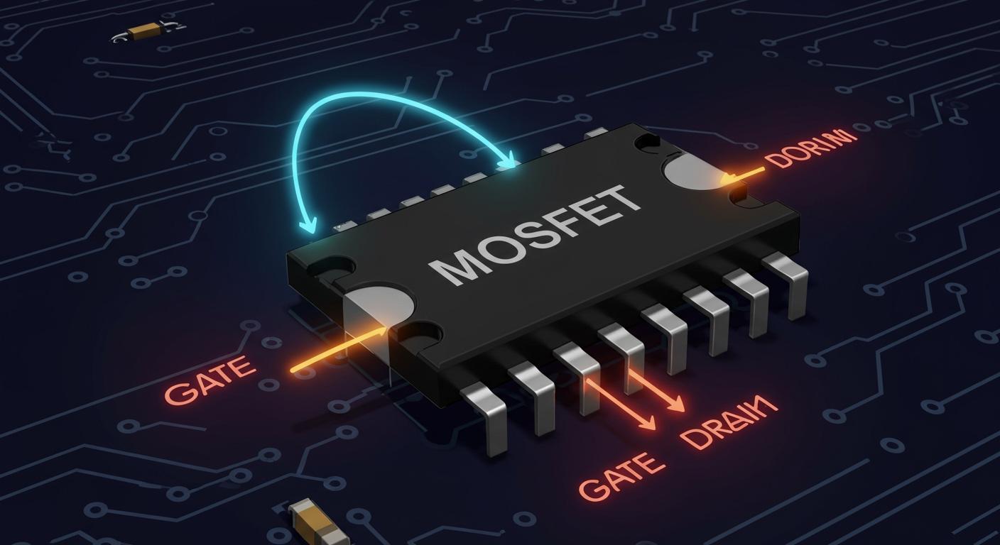
A metal oxide semiconductor field effect transistor (MOSFET) is a voltage-controlled electronic switch. You can think of a MOSFET like a water valve. A tiny turn (voltage) controls a huge flow of water (current). This simple mosfet transistor is a key part of your smartphone and laptop. The power mosfet market shows its massive scale.
| Metric | Value |
|---|---|
| Global Power MOSFET Market Size (2025) | USD 31481.8 million |
| Projected CAGR (2025-2033) | 9.80% |
This guide will help you understand the mosfet. You will build your first simple circuit with a mosfet.
Key Takeaways
- A MOSFET is a voltage-controlled switch. It uses a small voltage to control a larger current. This makes it very efficient.
- MOSFETs have three main parts: a Gate, a Drain, and a Source. The Gate controls if the MOSFET is on or off.
- N-Channel MOSFETs are common for beginners. They work well for turning things on and off from the low side of a circuit.
- Most MOSFETs are 'enhancement-mode.' This means they are off until you apply a voltage to the Gate.
- You can build a simple circuit with a MOSFET to turn an LED on and off. Always protect MOSFETs from static electricity.
What is a MOSFET Transistor?
The full name for a MOSFET is a metal oxide semiconductor field effect transistor. Mohamed Atalla and Dawon Kahng at Bell Labs invented this device. They first demonstrated a working MOSFET in 1959. Today, the MOSFET is a fundamental building block in electronics. You will find this mosfet transistor in nearly every modern device.
The Three Terminals: Gate, Drain, and Source
Every standard MOSFET has three connection points, called terminals. Understanding these is the first step to using a MOSFET.
- Gate (G): This is the control terminal. You apply a voltage here to turn the MOSFET on or off.
- Drain (D): This is where the electrical current typically enters the MOSFET.
- Source (S): This is where the electrical current leaves the MOSFET.
Inside the MOSFET, the gate is separated from the other parts by a very thin insulating layer. This layer is key to how the MOSFET works.
The Voltage-Controlled Switch Analogy
A MOSFET acts as a voltage-controlled device. A Bipolar Junction Transistor (BJT), another common transistor, is a current-controlled device. This is a major difference. You control a BJT with a small current, but you control a MOSFET with a voltage. The gate of the MOSFET requires almost no current to operate.
Key Difference: A BJT needs a continuous input current to stay on. A MOSFET only needs an input voltage to stay on.
| Feature | BJT (Bipolar) | MOSFET (Unipolar) |
|---|---|---|
| Control Method | Current-controlled | Voltage-controlled |
| Input Power | Higher | Lower (more efficient) |
| Common Use | Amplification | Switching & Digital Logic |
This voltage control makes the mosfet transistor extremely efficient for switching tasks.
Why High Input Impedance Matters
The term "high input impedance" sounds complex, but the idea is simple. Because the gate is insulated, it strongly resists (or impedes) any current from flowing into it. This is a huge advantage.
N-Channel vs. P-Channel Types
You will find that the mosfet comes in two main flavors: N-Channel and P-Channel. Think of them as two different types of valves. One opens with a push, and the other opens with a pull. Choosing the correct type is essential for your circuit to work as you intend.
N-Channel: The Common Low-Side Switch
The N-Channel mosfet is the most popular type for hobbyists and beginners. You turn this mosfet on by applying a positive voltage to its gate terminal relative to its source.
This mosfet is perfect for creating a low-side switch. In this setup, you place the mosfet between your load (like an LED or motor) and the ground connection. When you activate the gate, the mosfet completes the circuit to ground, turning your load on. You will often see this circuit used to control a DC motor with a microcontroller. Because of its high efficiency, the N-Channel mosfet is a fantastic choice. This efficiency comes from its very low on-resistance. Electrons are the charge carriers in an N-Channel device, and they move more easily, resulting in less wasted power and heat.
P-Channel: The High-Side Switch
The P-Channel mosfet works the opposite way. You turn it on by applying a voltage to its gate that is lower than its source voltage.
You typically use a P-Channel mosfet to build a high-side switch. This circuit places the mosfet between the positive power supply and the load. When you pull the gate voltage low, the mosfet allows current to flow from the power source into your load. While a P-Channel mosfet is simpler for this task, it has drawbacks. It relies on different charge carriers that have lower mobility. This gives the P-Channel mosfet a higher on-resistance, making it less efficient and producing more heat than a comparable N-Channel mosfet.
💡 Why not use an N-Channel for everything? Building a high-side switch with an N-Channel mosfet is complex. You would need a special circuit to create a gate voltage that is even higher than your main power supply.
Quick Chart: Choosing the Right Type
Use this simple chart to help you decide which mosfet is right for your project.
| Feature | N-Channel MOSFET | P-Channel MOSFET |
|---|---|---|
| On-Resistance | Lower (More Efficient) | Higher (Less Efficient) |
| Switching Speed | Faster | Slower |
| Typical Cost | Lower | Higher |
| Circuit Simplicity | Simple for Low-Side | Simple for High-Side |
For most beginner projects, the N-Channel mosfet is the clear winner due to its lower cost and higher performance.
Enhancement vs. Depletion Mode
You now know about N-Channel and P-Channel types. The next layer of understanding a mosfet involves its "mode." Every mosfet is either an enhancement-mode or a depletion-mode type. This simply tells you if the mosfet is naturally on or off.
Enhancement-Mode (Normally-OFF)
An enhancement mode mosfet is "normally-off." Think of it as a closed door. Current cannot flow from the drain to the source until you apply the correct voltage to the gate. Applying this voltage "enhances" the channel, allowing current to pass. This is the most common type of mosfet you will encounter.
The vast majority of MOSFETs used today are enhancement-mode. This makes the enhancement mode mosfet your default choice for most switching projects.
| MOSFET Type | Market Share (2024) |
|---|---|
| Enhancement-mode | 72% |
| Depletion-mode | Less common |
You can find this enhancement mode mosfet in many devices you use daily.
- Switch-mode power supplies (SMPS)
- Motor controllers
- DC-DC converters
- Car audio setups
The enhancement mode mosfet is perfect for applications where you want a circuit to be off until you decide to turn it on.
Depletion-Mode (Normally-ON)
A depletion mode mosfet is the opposite; it is "normally-on." This mosfet acts like an open door, allowing current to flow freely when no voltage is on the gate. You must apply a specific voltage to the gate to "deplete" the channel and turn the mosfet off.
While less common, the depletion mode mosfet is essential for certain jobs. You use a depletion mode mosfet in circuits that need to be active by default. Some key applications include:
- Constant Current Sources: A depletion mode mosfet helps deliver steady current for things like LED drivers.
- Surge Protection: This mosfet can protect sensitive electronics from sudden voltage spikes.
- Solid-State Relays: A depletion mode mosfet can create a reliable, fast-switching electronic relay.
You will not use a depletion mode mosfet for your first projects, but it is good to know this type of mosfet exists. The depletion mode mosfet solves unique engineering challenges.
Reading Schematic Symbols
You can tell the mode of a mosfet by its circuit symbol. An enhancement-mode symbol has a broken or dashed line between the drain and source. This shows the channel is normally open. A depletion mode mosfet symbol has a solid, unbroken line, showing the channel is normally closed and ready to conduct.
| Type | N-Channel Symbol | P-Channel Symbol |
|---|---|---|
| Enhancement | (Broken Line) | (Broken Line) |
| Depletion | (Solid Line) | (Solid Line) |
This simple visual difference helps you quickly identify the mosfet type in any circuit diagram.
Your First MOSFET Circuit
You have learned the theory. Now it is time to put your knowledge into practice. You will build a simple but powerful circuit. This circuit uses an N-Channel enhancement-mode mosfet to switch an LED on and off. This project will show you the magic of a mosfet in action.
Required Components and Schematic
First, you need to gather a few common electronic parts. You can find these in most beginner electronics kits or purchase them online.
- Breadboard: A board for building temporary circuits.
- MOSFET: 1 x 2N7000 (a common N-Channel enhancement-mode mosfet).
- LED: 1 x 5mm LED (any color).
- Resistors:
- 1 x 330Ω resistor (for the LED).
- 1 x 220Ω resistor (for the gate).
- 1 x 10kΩ resistor (for pull-down).
- Power Source: 1 x 9V battery and a battery clip.
- Switch: 1 x Pushbutton.
- Jumper Wires: A few wires to connect everything.
Here is the basic layout of your circuit. The mosfet acts as a switch between the LED and ground.
          +9V
           |
          330Ω
           |
          LED (Anode)
           |
(Drain)---MOSFET---(Source)
           |         |
         (Gate)      GND
           |
          220Ω
           |
(Button)---o--- 10kΩ --- GND
           |
          +9V
Why do you need those extra resistors?
- Gate Resistor (220Ω): This resistor protects your control source. For slow switching like this, a value from 10Ω to 500Ω works well. It limits the initial rush of current into the gate.
- Pull-Down Resistor (10kΩ): This resistor is very important. It connects the gate to ground when the button is not pressed. This prevents the gate from "floating" and turning the mosfet on from stray electrical noise. It ensures the mosfet stays firmly off.
The value of the pull-down resistor depends on your circuit's power. For most hobby projects, a 10kΩ resistor is a perfect choice.
| Power Supply Range | Recommended Pull-Down Resistor |
|---|---|
| Low to Medium (0-500W) | 10K-20K |
| High Power | 4.7K-10K |
Step-by-Step Circuit Assembly
Follow these steps carefully on your breadboard. Take your time and double-check your connections.
- Place the MOSFET: Gently press the 2N7000 mosfet into the breadboard. Make sure its three legs are in separate rows. The flat side of the 2N7000 faces you. From left to right, the pins are Source, Gate, and Drain.
- Connect the Source: Use a jumper wire to connect the Source pin (left pin) of the mosfet to the ground rail of your breadboard.
- Connect the Load: Connect the Drain pin (right pin) of the mosfet to the short leg (cathode) of your LED. Connect the long leg (anode) of the LED to one end of the 330Ω resistor. Connect the other end of that resistor to the positive power rail.
- Connect the Gate: Connect the Gate pin (middle pin) of the mosfet to one end of the 220Ω gate resistor.
- Add the Button and Pull-Down: Connect the other end of the 220Ω resistor to one side of your pushbutton. Connect that same point to one end of the 10kΩ pull-down resistor. Connect the other end of the 10kΩ resistor to the ground rail.
- Power the Button: Connect the other side of your pushbutton to the positive power rail.
- Apply Power: Connect your 9V battery. The positive wire goes to the positive rail, and the negative wire goes to the ground rail.
Now, press the button. The LED should light up! Release the button, and the LED should turn off. You have successfully built a mosfet transistor switch. This works because the gate has very high impedance. It needs almost no current from the button to turn the mosfet on, making it a very efficient switch.
💡 Circuit Not Working? Try This! If your LED does not turn on or off correctly, here are a few troubleshooting steps:
- Check Your Wiring: Carefully review all your connections against the schematic. A misplaced wire is the most common problem.
- Test the MOSFET Manually: Remove the button and resistors from the gate. Use a jumper wire to connect the gate directly to ground (the LED should be off). Then, connect the gate directly to the +9V rail (the LED should be on). This confirms the mosfet itself is working.
- Verify Resistors: Make sure you used the correct resistor values. The 10kΩ pull-down is crucial for keeping the mosfet off.
Threshold Voltage (Vth) in Action
Your circuit works because of a key parameter called Gate Threshold Voltage (Vth). This is the minimum voltage required between the gate and source to start turning the mosfet on.
- Gate-Source Voltage (Vgs): In your circuit, this is the voltage at the gate pin compared to the source pin (which is at ground, or 0V). When you press the button,
Vgsbecomes high. - Drain Voltage (Vd): This is the voltage at the drain pin. When the mosfet is off,
Vdis high (near 9V). When the mosfet is on,Vddrops to nearly 0V, allowing current to flow through the LED.
When you press the button, the Vgs rises above the Vth of the mosfet. This creates a conductive channel inside the mosfet, allowing current to flow from drain to source and light the LED. When you release the button, the pull-down resistor pulls Vgs back to 0V, which is below Vth, and the mosfet turns off.
You can find the Vth for a mosfet in its datasheet. For our 2N7000 mosfet, the datasheet shows this:
| Parameter | Symbol | Min | Max | Unit |
|---|---|---|---|---|
| Gate Threshold Voltage | VGS(th) | 0.8 | 2.5 | V |
This means the 2N7000 mosfet will start to turn on when the gate voltage is somewhere between 0.8V and 2.5V. To make the mosfet fully on and highly conductive, you need a Vgs well above the threshold. This state is called strong inversion, where the mosfet acts like a closed switch with very low resistance.
Protecting from Static Discharge (ESD)
A mosfet is extremely sensitive to static electricity. The gate is separated from the rest of the component by an incredibly thin layer of oxide. A small zap of static from your finger can easily puncture this layer and destroy the mosfet.
- The thin gate oxide cannot handle high voltage, even for a microsecond.
- ESD can cause a catastrophic failure where the mosfet no longer works at all.
- It can also cause hidden damage that makes the mosfet unreliable or fail later.
You must handle your mosfet with care. Follow these simple rules to protect it from ESD.
- Ground Yourself: Before you touch the mosfet, touch a large metal object that is grounded, like a metal desk leg or the metal case of a plugged-in computer. This discharges any static buildup from your body.
- Work on a Safe Surface: Avoid working on carpet or with materials that create static, like styrofoam. A wood table or a special static-dissipative mat is best.
- Minimize Movement: Shuffling your feet or shifting in your chair can build up static. Try to stay still while handling sensitive components.
- Keep it in Packaging: Leave the mosfet in its anti-static packaging until you are ready to use it.
By following these simple steps, you can keep your components safe and ensure your projects are successful.
You now understand the most important idea. A metal oxide semiconductor field effect transistor, or mosfet, is an efficient voltage-controlled switch. You learned about the main mosfet types:
- N-Channel or P-Channel
- Enhancement or Depletion mode
For your first projects, the N-Channel enhancement mode mosfet is your best choice. This mosfet transistor is a reliable mosfet. Build the example circuit. You can experiment with this mosfet. The enhancement mode mosfet is very versatile.
💡 Next Step: Try controlling the LED's brightness. You can use Pulse Width Modulation (PWM) from a microcontroller. This signal rapidly switches the enhancement mode mosfet. This makes the mosfet a dimmer switch for your mosfet circuit.
FAQ
What is the most common mosfet for beginners?
You should start with an N-Channel enhancement-mode mosfet. This type of mosfet is perfect for your first projects. The N-Channel mosfet works well as a simple low-side switch. This specific mosfet is also very efficient and low-cost.
Why does my mosfet get hot?
Your mosfet creates heat from its internal resistance, called
RDS(on). A better mosfet has lower resistance and produces less heat. High current flow through the mosfet will also generate more heat. This makes the mosfet less efficient.
Can I control a mosfet with an Arduino?
Yes, you can easily control a mosfet with an Arduino or other microcontrollers.
- A logic-level mosfet is the best choice for this task.
- It turns on fully with the 3.3V or 5V signal from a digital pin.
- This lets you control a high-power device with a low-power signal from the mosfet.
Do I always need a gate resistor for a mosfet?
💡 A gate resistor protects your control source and the mosfet. It limits the initial current rush to the gate. This is very important for high-speed switching. You should always use one to build a reliable circuit with your mosfet.