Never Misread a Sensor Again with ADS1115
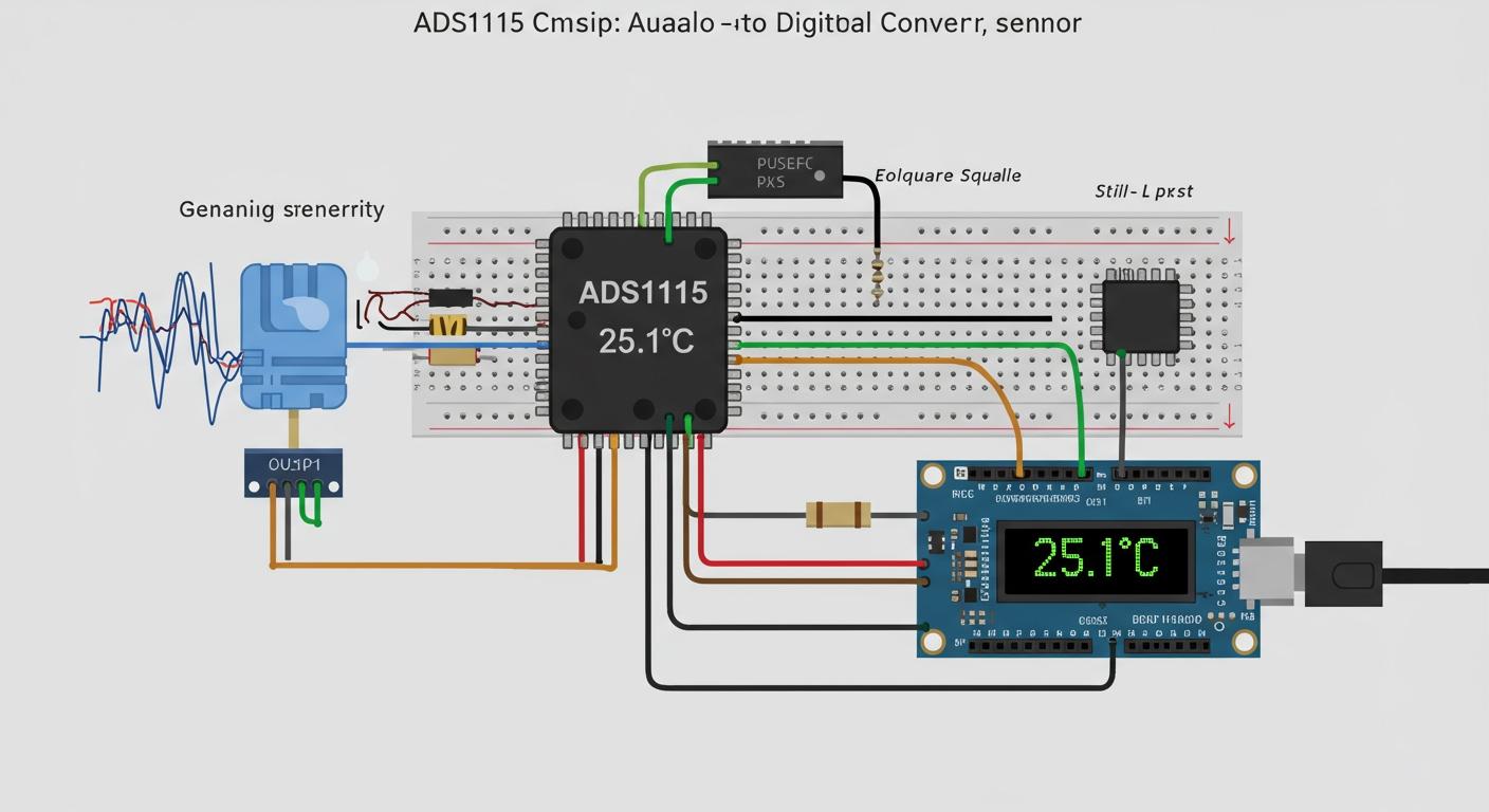
You might notice your sensor readings from an Arduino jump around. The built-in analog-to-digital converter (ADC) on an Arduino or ESP32 has limits. Your Arduino ADC provides steady readings, but an ESP32 ADC can be noisy. This affects how you read sensor data.
| Microcontroller | Resolution | Accuracy Characteristics |
|---|---|---|
| Arduino Uno R3 | 10-bit | Very little deviation between readings, great linearity across the whole 5V range. |
| ESP32 | 12-bit | Sizeable dead zone until ~0.05V, significant noise (large error bars), but good linearity after the dead zone up to 1V. |
The Solution: Meet the ADS1115, a powerful 16-bit differential ADC. This amazing ADC helps you read sensor data with high precision. The ADS1115 makes your analog signal reading reliable. The ADS1115 provides stable sensor data for your projects. You can trust the analog data from your sensor with the ADS1115. Your Arduino projects will see a huge improvement. The ADS1115 is the upgrade your Arduino needs for a better sensor ADC.
Key Takeaways
- The ADS1115 is a 16-bit ADC. It gives more accurate sensor readings than Arduino's built-in ADC.
- The ADS1115 has a Programmable Gain Amplifier (PGA). This helps to amplify small sensor signals for better accuracy.
- The ADS1115 uses differential inputs. This feature helps reduce noise in your sensor data.
- Wiring the ADS1115 is simple. It uses only two wires for data with the I2C protocol.
- You must choose the correct gain setting. This prevents inaccurate or damaged readings from your sensor.
KEY ADS1115 FEATURES FOR PRECISION
The ADS1115 is more than just an ADC; it's a toolkit for precision. It has specific features that help you get clean, reliable data from any analog sensor. Understanding these features allows you to move beyond the limitations of the standard Arduino ADC.
10-BIT VS. 16-BIT RESOLUTION
You can think of resolution like the markings on a ruler. Your Arduino Uno's built-in 10-bit ADC is like a basic ruler with 1,024 markings (2^10). For a 5V system, the smallest change it can detect is 4.88mV. This is often good enough, but for a sensitive sensor, it can miss small details.
The ADS1115 gives you 16-bit resolution. This is like upgrading to a precision caliper with 65,536 markings (2^16). On the same 5V system, the ADS1115 can detect a voltage change as small as 76 microvolts (µV). This massive increase in resolution means your readings will be far more detailed and accurate. This precision is essential when your sensor data needs to be exact.
USING THE PROGRAMMABLE GAIN AMPLIFIER
The ADS1115 includes a Programmable Gain Amplifier (PGA). This feature lets you "zoom in" on your analog signal. Many sensors only output a very small voltage. The PGA can amplify this small signal before the ADC performs the sampling. This allows the signal to use more of the ADC's full 16-bit resolution.
Note: The ADS1115 uses the simple I2C communication protocol. This means you only need two wires to connect it to your Arduino, which keeps your circuit clean.
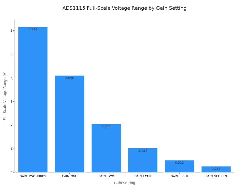
You can choose from several gain settings to match your sensor's output range. A higher gain is perfect for a sensor with a tiny voltage output, giving you much better sampling and more stable readings.
| Gain Setting | Full-Scale Voltage Range (V) |
|---|---|
GAIN_TWOTHIRDS | ±6.144 |
GAIN_ONE | ±4.096 |
GAIN_TWO | ±2.048 |
GAIN_FOUR | ±1.024 |
GAIN_EIGHT | ±0.512 |
GAIN_SIXTEEN | ±0.256 |
DIFFERENTIAL INPUTS FOR NOISE REDUCTION
Noise is a common problem in electronics. The ADS1115 helps you fight it with its differential input capability. Instead of measuring one analog signal against ground, this 16-bit differential ADC can measure the voltage difference between two input pins.
This is a powerful feature. Any electrical noise that affects both wires in the circuit will be ignored by the ADC. The ADS1115 only measures the true signal from the sensor. This is extremely useful for sensors that produce very small voltage changes, such as:
- Load Cells / Strain Gauges
- Pressure Sensors
- Thermocouples
Using differential inputs is a professional technique for getting clean data, and the ADS1115 makes it easy to implement in your Arduino projects, like a high-precision data logger. The simple I2C interface of the ADS1115 makes connecting it to your Arduino a breeze.
WIRING YOUR BREAKOUT BOARD
Getting the hardware connected is the first hands-on step to unlocking high-precision data. You will find that wiring the ADS1115 is straightforward thanks to its use of the I2C protocol. This section provides the essential steps to build your circuit correctly for your Arduino or Raspberry Pi projects.
REQUIRED COMPONENTS
Before you begin, you need to gather a few common components. Having these ready will make the process smooth and simple. Here is what you will need for your projects:
- A microcontroller (like an Arduino Uno or Raspberry Pi)
- An ADS1115 breakout board
- An analog sensor (a photoresistor or MQ-135 gas sensor are great starting points)
- A solderless breadboard
- Jumper wires
PINOUT AND WIRING DIAGRAM
The ADS1115 breakout board has several pins, but you only need to connect a few for basic operation. Understanding each pin's function is key to a successful circuit. The simple I2C communication interface on the ADS1115 makes it a favorite in many tutorials.
| Pin | Name | Description |
|---|---|---|
| VDD | Power | Connect this to the power supply of your microcontroller (5V for Arduino, 3.3V for Raspberry Pi). |
| GND | Ground | Connect this to the ground (GND) pin on your microcontroller. |
| SCL | Serial Clock | This is the I2C clock line. Connect it to the SCL pin on your Arduino or Raspberry Pi. |
| SDA | Serial Data | This is the I2C data line. Connect it to the SDA pin on your Arduino or Raspberry Pi. |
| ADDR | Address | This pin sets the I2C address of the ADC. |
| ALRT | Alert/Ready | This is an optional pin that can signal when a new ADC reading is ready. |
To get your ADS1115 running, you will connect the four main I2C pins. Connect VDD and GND from the ADS1115 to the corresponding power pins on your Arduino or Raspberry Pi. Then, connect the SCL and SDA pins to the matching I2C pins on your microcontroller. For the ADDR pin, you can set one of four different I2C addresses. This feature allows you to use up to four ADS1115 ADC modules on a single I2C bus. To use the default address (0x48), you simply connect the ADDR pin to GND. You can also connect it to VDD, SDA, or SCL to select other addresses.
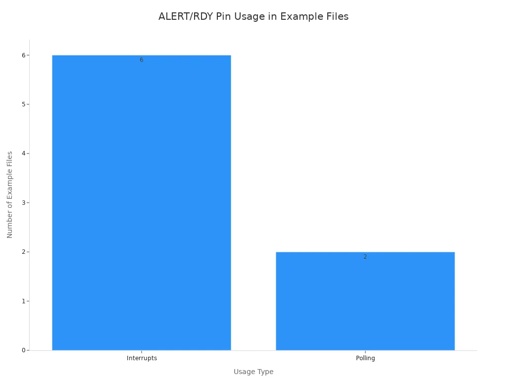
The ALERT/RDY pin is a powerful feature for advanced projects. You can use it to signal that an ADC conversion is complete. When the pin goes low, your Arduino or Raspberry Pi knows that new data is ready for sampling. This method is much faster than constantly asking the ADC if it's done. While optional, using this pin is great for a high-speed data logger. It operates as an open collector, so you will need to add an external pull-up resistor (10kΩ is common) to your circuit. You can use it for interrupts or for polling.
CONNECTING THE SENSOR
With the ADS1115 wired to your microcontroller, you are ready to connect your analog sensor. The ADS1115 has four analog input channels, labeled A0, A1, A2, and A3. You can connect your sensor's analog output pin to any of these channels. This setup allows you to get precise readings from your sensor.
For example, let's connect an MQ-135 gas sensor to your circuit. You will connect the sensor's VCC and GND pins to your power source and ground. Then, you connect the sensor's analog output pin (often labeled AOUT) directly to one of the ADS1115 input channels, such as A0. This simple connection allows the high-resolution ADC to perform its sampling on the sensor's signal. This is a common setup for both Arduino and Raspberry Pi. For a Raspberry Pi, you might use Python to read the data.
# read analog sensor on channel Ax [0-3]
result = adc.readADCSingleEnded(1, gain, sps) / 1000

# print result
print "MQ-2: %.6f" % (result)
This configuration ensures that the ADS1115 ADC captures the subtle voltage changes from the sensor, giving you far more accurate data than a standard Arduino ADC could provide. Your Raspberry Pi can also benefit from this precise analog input.
CODING WITH THE ADS1115
With your circuit wired, you are ready to bring your project to life with code. The software side is where you tell the microcontroller how to communicate with the ADS1115 and interpret its high-precision data. This section guides you through setting up the Arduino IDE, understanding a complete code example, and converting raw ADC values into useful voltage readings. You will find the process is very similar for Raspberry Pi projects using Python.
ARDUINO IDE LIBRARY SETUP
Your Arduino board does not know how to talk to the ADS1115 ADC by default. You need to install a library, which is a collection of pre-written code that handles the complex I2C communication for you. For the ADS1115, the "Adafruit ADS1X15" library is a popular and excellent choice for many tutorials.
You can install the library directly from the Arduino IDE. Follow these simple steps:
- Go to
Sketch->Include Library->Manage Libraries… - Type “Adafruit ADS1X15” into the search box.
- Find the library in the list and click the
Installbutton. - Close and restart the Arduino IDE. This action ensures the new library is loaded correctly.
After installation, you should verify that your Arduino can communicate with the ADS1115 sensor. You can use a short sketch to check the connection. If the I2C connection fails, the code will print an error message. This is a great way to debug your circuit early.
You can also use an I2C Address Scanner program. This tool scans for connected devices and tells you their address. It helps you confirm your ADS1115 is visible to the Arduino before you write your main code.
#include <Adafruit_ADS1X15.h>

Adafruit_ADS1115 ads;  /* Create an ADS1115 object */

void setup(void) {
  Serial.begin(9600);
  Serial.println("Getting ready to read from the ADS1115!");

  // Initialize the ADS1115
  if (!ads.begin()) {
    Serial.println("Failed to initialize ADS. Check your wiring!");
    while (1); // Halt the program if it can't connect
  }
}

void loop(void) {
  // You will add your sensor reading code here later
}
EXAMPLE CODE WALKTHROUGH
Now you can write the full code to get analog readings from a sensor. This example shows you how to read a single-ended input from channel A0. We will read the raw ADC value and print it to the Serial Monitor. This same logic can be applied to a Raspberry Pi using Python.
The code below sets up the ADS1115, configures the gain, and continuously reads the analog sensor value. Each part of the code has comments to explain what it does.
#include <Wire.h>
#include <Adafruit_ADS1X15.h>

Adafruit_ADS1115 ads;  /* Use this for the 16-bit ADS1115 ADC */

void setup(void) {
  Serial.begin(9600);
  Serial.println("Reading from the ADS1115 ADC!");

  // The ADC gain determines the voltage range.
  // GAIN_TWOTHIRDS: +/-6.144V  (1 bit = 0.1875mV)
  // GAIN_ONE:      +/-4.096V  (1 bit = 0.125mV)
  // GAIN_TWO:      +/-2.048V  (1 bit = 0.0625mV)
  // GAIN_FOUR:     +/-1.024V  (1 bit = 0.03125mV)
  // GAIN_EIGHT:    +/-0.512V  (1 bit = 0.015625mV)
  // GAIN_SIXTEEN:  +/-0.256V  (1 bit = 0.0078125mV)
  ads.setGain(GAIN_ONE); // Set gain to 1 for a +/- 4.096V range

  if (!ads.begin()) {
    Serial.println("Failed to initialize ADS. Check wiring!");
    while (1);
  }
}

void loop(void) {
  int16_t adc0; // Variable to store the 16-bit ADC value

  // Read the single-ended input from channel 0
  adc0 = ads.readADC_SingleEnded(0);

  Serial.print("A0 Raw Value: ");
  Serial.println(adc0);

  delay(1000); // Wait a second before the next reading
}
A Note on Sampling Speed: The ADS1115 can perform up to 860 samples per second (SPS). You can try to set this in the Adafruit library using
ads.setDataRate(RATE_ADS1115_860SPS);. However, the library has built-in delays that may prevent you from reaching the true maximum speed. For high-speed projects like a real-time data logger, you might explore other libraries. TheADS1115_WEorjrowberg/i2cdevliblibraries offer more direct control over sampling rates and are great alternatives for advanced Arduino or Raspberry Pi applications. A Raspberry Pi with Python can also achieve fast sampling.
CONVERTING RAW VALUES TO VOLTAGE
The readADC_SingleEnded() function returns a raw integer value. For the 16-bit ADS1115, this number ranges from -32,768 to 32,767. This raw data is not very useful on its own. You need to convert it into a meaningful voltage that relates to your sensor's behavior.
The conversion formula depends on the gain setting you chose. The gain sets the maximum voltage the ADC can measure. The library simplifies the math, but understanding the concept is key.
First, you find the voltage value of a single ADC count. You do this by dividing the full-scale voltage range by the total number of possible values (65,536).
Let's use the GAIN_ONE setting from our example, which has a range of ±4.096V.
- Full-Scale Voltage: 4.096 V
- ADC Resolution: 16-bit, so the positive range is 32,767 steps.
- Voltage per bit = 4.096 V / 32767 = 0.000125 V or 0.125 mV.
To get the final voltage, you multiply the raw ADC reading by this "voltage per bit" value. The Adafruit library provides a handy function, computeVolts(), that does this for you.
Here is how you would modify the loop() function to display the voltage:
void loop(void) {
  int16_t adc0;
  float volts0;

  adc0 = ads.readADC_SingleEnded(0);

  // The library function makes conversion easy!
  volts0 = ads.computeVolts(adc0);

  Serial.print("A0 Raw: ");
  Serial.print(adc0);
  Serial.print("\tVoltage: ");
  Serial.print(volts0, 4); // Print voltage with 4 decimal places
  Serial.println("V");

  delay(1000);
}
Now, your Serial Monitor will show both the raw value and the calculated voltage. This gives you accurate, easy-to-read data from your analog sensor, which is the ultimate goal when using a precision ADC like the ADS1115 in your Arduino or Raspberry Pi circuit. This precise sampling is what makes the ADS1115 so powerful.
TIPS FOR ACCURATE READINGS
You have your circuit and code ready. Now, you can fine-tune your setup to get the best possible data. These tips will help you solve common problems and ensure your sensor readings are always accurate for your Arduino or Raspberry Pi projects.
CHOOSING THE CORRECT GAIN
You must choose your gain carefully. Think of it like a microphone volume. Too low, and you will not hear the quiet sounds. Too high, and everything becomes distorted. Your goal is to match the gain to your sensor's maximum output voltage. If your analog sensor outputs a maximum of 2V, you should use the GAIN_TWO setting (±2.048V). This uses the full power of the ADC for the best sampling.
⚠️ Warning: Never let your sensor's input voltage exceed the gain's voltage range. An input voltage higher than the gain setting will "clip" the signal, causing maxed-out readings. Worse, an input voltage that exceeds the ADS1115 power supply (e.g., 4V into an ADC powered by 3.3V) can permanently damage the ADC chip. Always check your sensor datasheet. This applies to both Arduino and Raspberry Pi setups using Python.
SOLVING COMMON I2C ISSUES
Sometimes your Arduino or Raspberry Pi cannot find the ADS1115 on the I2C bus. If your I2C scanner sketch finds nothing, do not panic. First, check these common issues:
- You have a bad or loose connection in your circuit.
- The SCL and SDA wires are swapped.
- The ADS1115 address pin is not connected correctly.
An I2C scanner on your Arduino might detect the ADC, but you still get no data. This can happen if you use software I2C instead of the dedicated hardware I2C pins (A4/A5). Similarly, a Raspberry Pi using Python might see the sensor with a scanner tool but fail to get readings due to a library issue. Always start with the hardware I2C pins for the most reliable connection.
FIXING MAXED-OUT OR ZERO READINGS
If your ADC consistently returns the maximum value (like 32767), your gain is likely set too low for the sensor's voltage. If your ADC always returns zero, the problem can be in your software or hardware.
A hardware cause for zero readings is a "floating" analog input. This happens when the sensor pin is not properly connected. You can often fix this by connecting a 100kΩ resistor between the ADC input pin (e.g., A0) and Ground. This gives the ADC a stable reference point. This simple fix works for both an Arduino and a Raspberry Pi with Python.
The ADS1115 adc is a key upgrade for your Arduino and Raspberry Pi projects. This adc gives your Arduino precise sensor data. Your Arduino can now get better sensor readings. You can move past the limits of the built-in Arduino adc. Your Arduino and Raspberry Pi projects will improve. Your Raspberry Pi can use this adc, too. Start using this adc with your sensor. Your Arduino will see the better data. Your Raspberry Pi will get great sensor readings. Your Arduino is ready for this adc.
Now you have the tools and knowledge to achieve precision in your own projects. Start experimenting and see the difference for yourself!
FAQ
Can I use multiple ADS1115 modules in one project?
Yes, you can connect up to four ADS1115 modules to a single I2C bus. You give each module a unique address by connecting its ADDR pin to either GND, VDD, SDA, or SCL. Your arduino project can then read from all of them.
What is the difference between the ADS1115 and ADS1015?
The ADS1115 provides high-precision 16-bit resolution. The ADS1015 is a similar chip but offers 12-bit resolution. The ADS1015 is faster, but the ADS1115 gives you more detailed and accurate measurements for your sensors.
Does the ADS1115 work with 3.3V microcontrollers?
Yes, the ADS1115 is very flexible. It works perfectly with 3.3V logic and power, like on an ESP32 or Raspberry Pi. You just connect the VDD pin to your board's 3.3V output. This makes it a great choice for any modern arduino compatible board.
Why are my sensor readings negative?
You will see negative values when using the differential mode. This happens when the voltage on the second input pin is higher than the voltage on the first. The ADC is correctly measuring the negative voltage difference between the two inputs.