Arduino PID Controller A Complete Tutorial
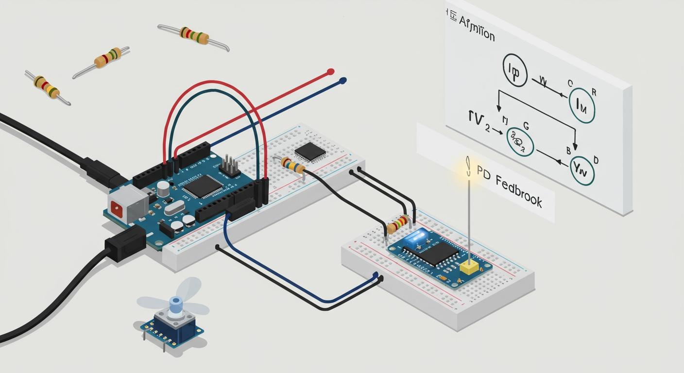
You can build your own Arduino PID controller. A PID controller works like you in a shower. You feel the water and adjust the knob. This is a simple feedback control system. Our PID design uses three parts for smart control. The Proportional part acts on the current error. The Integral part fixes past errors. The Derivative part predicts future errors. You will build a controller to precisely manage a DC motor's speed. The final step is the careful tuning of this PID controller.
Project Requirements ⚙️
- Hardware:
- Arduino Uno or similar
- DC Motor with Encoder
- L298N Motor Driver
- 12V Power Supply
- Jumper Wires
- Software:
- Arduino IDE
Key Takeaways
- A PID controller uses three parts: Proportional (P) for current error, Integral (I) for past errors, and Derivative (D) for future error prediction. This helps control things like motor speed.
- You need specific hardware like an Arduino, a DC motor with an encoder, and a motor driver. The encoder tells the Arduino the motor's speed.
- The Arduino code reads sensor data, calculates the error between the target and actual speed, and then uses PID logic to adjust the motor. This process repeats constantly.
- Tuning the PID controller means finding the right values for Kp, Ki, and Kd. This makes the motor reach the target speed quickly and smoothly without overshooting.
- The Arduino Serial Plotter is a key tool for tuning. It shows you how your motor reacts in real-time as you change the Kp, Ki, and Kd values.
PID Controller Fundamentals
A PID controller is a powerful tool for your projects. You can master its design by understanding its three core parts. This feedback control system intelligently adjusts its output to hold a variable, like motor speed, exactly where you want it. Let's break down the P, the I, and the D.
The Proportional (P) Term
The Proportional term is your controller's immediate reaction. It looks at the current error—the difference between your target and the actual value—and applies a corrective force proportional to that error. A large error gets a large response, while a small error gets a small one. Think of it as the main muscle of your PID control.
The Integral (I) Term
The Integral term looks at the past. It eliminates persistent errors by continuously accumulating the error over time. Imagine your motor is slightly under speed due to friction. The P term alone might not overcome it. The I term sums up this small, lingering error until its output is large enough to push the system to the target, ensuring zero steady-state error. This is a key part of feedback pid control.
The Derivative (D) Term
The Derivative term predicts the future. It looks at how quickly the error is changing. If the error is shrinking rapidly, the D term applies a braking force to prevent the system from overshooting the target and oscillating. This damping action is crucial for a fast and stable control response in your feedback pid control design.
💡 PID in the Real World: A PID controller is used everywhere!
- Robotics: Manages the precise position of robotic arms.
- Motion Control: Regulates the speed and position of CNC machine axes.
- Flow Control: Manages pumps to maintain liquid levels in tanks.
The PID Formula Explained
Your Arduino is a digital controller, so it uses a discrete-time version of the PID formula. It calculates the total output by adding the P, I, and D components together at regular time intervals. Your main job during tuning is to find the right constants (gains) for each term.
| Component | Discrete-time Calculation in Code |
|---|---|
| Proportional | Kp * error |
| Integral | Ki * integral_sum |
| Derivative | Kd * (error - last_error) |
P, PI, and PD Variations
You do not always need the full PID design. Simpler variations are often better for a specific control system. A PI controller, which removes the derivative term, is excellent for systems where you need stability and want to avoid noise. This makes it a popular choice for feedback pid control.
| System Type | Why a PI Controller Works Well |
|---|---|
| Level Control | Provides a smooth and stable response for maintaining liquid levels. |
| Flow Control | Offers gradual control with minimal oscillations, perfect for valves. |
Choosing the right controller type is a key part of your project's design. A full PID controller gives you the most precise control for complex systems like self-balancing robots or drones.
Hardware and Wiring
You will now assemble the physical components. A correct wiring setup is the foundation of your project design. This stage connects the brain (Arduino) to the muscle (motor) and is crucial for a successful PID controller. Let's look at each part before connecting them.
Component Overview
Your project uses three main parts. The Arduino is your controller. The L298N motor driver acts as a bridge. The DC motor with an encoder provides both motion and feedback. For this speed control design, the encoder is essential. It tells the Arduino how fast the motor is spinning. This is different from a temperature project, where you might use a thermistor for its high sensitivity in a limited range. For our motion control design, the encoder is the right sensor.
A motor like the 'Micro DC Motor with Encoder-SJ01' is a great choice. You can see typical specifications for such a motor below.
| Component | Specification |
|---|---|
| DC Motor | 24V/150W |
| Rated Speed | 2500 +/- 5 % RPM |
| Encoder | 600 Pulses Per Revolution |
Step-by-Step Wiring
You will now connect everything. Follow these steps carefully to complete the circuit design.
- Connect the L298N's
IN1andIN2pins to Arduino digital pins5and6. - Connect the L298N's
ENApin to Arduino PWM pin~3. This allows for speed control. - Connect the motor's two power wires to the L298N's
OUT1andOUT2terminals. - Connect the motor encoder's Channel A and Channel B to Arduino interrupt pins
2and4. - Connect a 12V power supply to the L298N's
12VandGNDterminals. - Finally, connect the Arduino's
GNDto the L298N'sGNDto create a common ground.
⚠️ Common Wiring Mistakes:
- Incorrect Polarity: Reversing the 12V and GND wires can damage the L298N. Always double-check your connections.
- Power Issues: A weak power supply will cause poor motor performance. Use a multimeter to verify your voltage.
- Electrical Noise: Erratic motor behavior can result from electrical noise. A clean ground connection is a key part of a stable design.
The Circuit Diagram
A clear circuit diagram is your best friend. It is a visual map of your electronic design. Tools like Fritzing use standard symbols to make these diagrams easy to read. For example, resistors are marked with 'R' and capacitors with 'C'. Following a clear diagram helps you avoid the common wiring mistakes that can stop a project in its tracks. A good diagram ensures your physical build matches the intended control logic.
Implementing PID Control in Code
You have wired the hardware. Now you will bring your PID controller to life with code. This section guides you through writing the Arduino sketch. A good software implementation is essential for precise control. You will learn to structure your code, read sensor data, and implement the core PID logic. This is the final step in your PID controller design.
Sketch Setup and Variables
First, you need to set up your sketch and define the necessary variables. A clean setup makes your code easier to read and debug. This initial implementation step is critical for a successful project.
You will define pins for the motor driver and encoder. You also need variables for your PID logic. Most of these PID variables should be double or float types. This choice allows for more precise computation in your controller. Whole numbers like int are not accurate enough for the small adjustments a PID controller makes.
- PID Gains:
Kp,Ki,Kd. You will tune these later. - PID Variables:
setpoint,input,output,error,lastError,integralSum. - Time Control: You need variables to manage the loop timing. The
millis()function helps you run the PID calculation at a consistent interval. This creates a stable rhythm for your controller.
// Motor and Encoder Pin Definitions
const int ENA = 3;  // PWM Speed Control
const int IN1 = 5;
const int IN2 = 6;
const int ENCODER_A = 2; // Must be an interrupt pin
const int ENCODER_B = 4;

// PID Variables
double Kp = 2.0;  // Proportional gain
double Ki = 5.0;  // Integral gain
double Kd = 1.0;  // Derivative gain

double setpoint = 100; // Target RPM
double input, output;  // PID input (current RPM) and output (PWM value)

double error, lastError, integralSum;

// Time variables for PID calculation
unsigned long currentTime, lastTime;
double elapsedTime;
Reading Sensor Input
Your controller needs to know the motor's current speed. You get this information from the encoder. The encoder sends out electrical pulses as the motor shaft spins. You will use Arduino interrupts to count these pulses without missing any. An interrupt immediately pauses the main loop to run a special function, making it perfect for capturing fast signals.
Sensor readings can be noisy. This noise can cause your controller to react erratically. You can smooth the input using a software filter. A simple and effective implementation is a moving average filter.
- Moving Average Filter: This filter averages the last several sensor readings. It smooths out random spikes and gives you a more stable
inputvalue for your PID calculation. - Median Filter: This is another option. It sorts recent readings and picks the middle value. This method is excellent at ignoring extreme, one-off glitches in the data.
Using a filter is a key part of a robust PID control implementation. It prevents the derivative term from overreacting to noise.
Calculating The Error
The next step in your PID implementation is to calculate the error. The error is the difference between where you want to be (the setpoint) and where you are (the process variable). The entire PID controller works to make this error zero.
The calculation is simple subtraction. You will perform this calculation at the start of every PID loop.
e(t) = Setpoint – Process Variable
In your code, this looks like:
// The process variable 'input' is the measured RPM from the encoder
error = setpoint - input;
This single line is the foundation of your feedback control. A positive error means the motor is too slow. A negative error means it is too fast. The controller will use this value to decide what to do next.
The Core PID Logic
Here you will implement the P, I, and D calculations. This is the brain of your PID controller. The logic combines the present error, past errors, and future error prediction to create a single output. A key part of this implementation is managing time. The integral and derivative terms depend on how much time has passed between calculations.
You will use millis() to calculate the elapsedTime. This ensures your I and D terms behave correctly regardless of how fast your loop runs.
currentTime = millis();
elapsedTime = (double)(currentTime - lastTime) / 1000; // Time in seconds

// Proportional Term
double p_term = Kp * error;

// Integral Term
integralSum += error * elapsedTime;
double i_term = Ki * integralSum;

// Derivative Term
double derivative = (error - lastError) / elapsedTime;
double d_term = Kd * derivative;

// Combine for total output
output = p_term + i_term + d_term;

lastError = error;
lastTime = currentTime;
⚠️ Preventing Integral Windup: A common problem in PID control is "integral windup." This happens if a large error persists, causing the integral term to grow huge. When the system can finally respond, this massive integral value causes a large overshoot. You can prevent this with an anti-windup scheme. One simple implementation is to stop accumulating the integral term when the controller's output is already at its maximum or minimum limit.
if (output < outMax && output > outMin) { integralSum += (Ki * error); }This small check adds significant stability to your controller's design and is a professional touch for any PID implementation.
Controlling The Actuator
The final step in the loop is to use the calculated output to control the motor. The output from your PID logic is a theoretical value. You need to translate it into a signal the L298N motor driver understands. You will use the analogWrite() function, which sends a PWM signal.
- Constrain the Output: The
analogWrite()function accepts values from 0 to 255. Your PID output can be much larger or smaller. You must constrain it to this range. - Set Motor Direction: You can use the sign of the output to control direction (forward or reverse). For this speed control design, we will focus on one direction.
- Apply the Signal: You send the constrained value to the motor driver's ENA pin.
// Constrain the output to the PWM range (0-255)
double constrainedOutput = constrain(output, 0, 255);

// Set motor direction to forward
digitalWrite(IN1, HIGH);
digitalWrite(IN2, LOW);

// Write the PWM signal to the motor driver
analogWrite(ENA, constrainedOutput);
This completes one full cycle of the PID control loop. This process repeats continuously, making small adjustments to keep the motor speed locked onto your setpoint. This is the power of a PID controller.
The Complete Arduino Code
Here is the complete sketch. This code combines all the pieces: variable setup, encoder reading via interrupts, the PID calculation loop, and actuator control. You can upload this code to your Arduino to get your PID controller running. This final implementation is the result of your hardware and software design.
/*
  Arduino PID Controller - DC Motor Speed Control
  This sketch implements a PID controller to regulate the speed of a DC motor with an encoder.
*/

// Pin Definitions
const int ENA = 3;  // PWM Speed Control for L298N
const int IN1 = 5;  // Motor Direction
const int IN2 = 6;  // Motor Direction
const int ENCODER_A = 2; // Interrupt Pin 0
const int ENCODER_B = 4; // A regular digital pin is fine for this simple implementation

// PID Gains - These will need tuning
double Kp = 2.0;
double Ki = 5.0;
double Kd = 1.0;

// PID Variables
double setpoint = 100; // Target RPM
double input, output;
double error, lastError, integralSum;

// Encoder Variables
volatile long encoderCount = 0;
const int pulsesPerRevolution = 600; // Update with your motor's spec

// Time Variables
unsigned long currentTime, lastTime;
double elapsedTime;

void setup() {
  Serial.begin(9600);

  // Setup pins
  pinMode(ENA, OUTPUT);
  pinMode(IN1, OUTPUT);
  pinMode(IN2, OUTPUT);
  pinMode(ENCODER_A, INPUT_PULLUP);
  pinMode(ENCODER_B, INPUT_PULLUP);

  // Attach interrupt for Encoder Channel A
  attachInterrupt(digitalPinToInterrupt(ENCODER_A), readEncoder, RISING);

  // Set motor to spin forward
  digitalWrite(IN1, HIGH);
  digitalWrite(IN2, LOW);

  lastTime = millis(); // Initialize time
}

void loop() {
  // --- 1. Calculate RPM (Process Variable) ---
  currentTime = millis();
  elapsedTime = (double)(currentTime - lastTime);

  if (elapsedTime >= 100) { // Calculate RPM every 100ms
    // Disable interrupts temporarily to read encoderCount safely
    noInterrupts();
    long pulseCount = encoderCount;
    encoderCount = 0;
    interrupts();

    // Calculate RPM
    input = (double)(pulseCount * (60000.0 / pulsesPerRevolution)) / elapsedTime;

    // --- 2. Calculate PID Error ---
    error = setpoint - input;

    // --- 3. Compute PID Terms ---
    // Integral term with anti-windup
    integralSum += error * (elapsedTime / 1000.0);

    // Derivative term
    double derivative = (error - lastError) / (elapsedTime / 1000.0);

    // --- 4. Calculate PID Output ---
    output = (Kp * error) + (Ki * integralSum) + (Kd * derivative);

    // --- 5. Control the Actuator (Motor) ---
    double constrainedOutput = constrain(output, 0, 255);
    analogWrite(ENA, constrainedOutput);

    // --- 6. Update variables for next loop ---
    lastError = error;
    lastTime = currentTime;

    // Print values for tuning via Serial Plotter
    Serial.print("Setpoint:");
    Serial.print(setpoint);
    Serial.print(", Input:");
    Serial.println(input);
  }
}

// Interrupt Service Routine to count encoder pulses
void readEncoder() {
  encoderCount++;
}
Practical PID Tuning
You have built the hardware and written the code. Now comes the most important part: PID tuning. Tuning is the process of finding the perfect values for your Proportional (Kp), Integral (Ki), and Derivative (Kd) gains. A well-tuned PID controller will give you fast and precise control. A poor tuning job will result in a system that is slow, unstable, or inaccurate. This is where your project's design truly comes to life.
The Goal of Tuning
The goal of tuning is to make your controller react perfectly to changes. You want the motor's speed (the process variable) to reach your target speed (the setpoint) quickly and smoothly. A great response has minimal overshoot and settles quickly without error. You can measure the quality of your control with a few key terms.
| Characteristic | What It Looks Like on a Graph |
|---|---|
| Rise Time | The time it takes for the motor speed to go from 10% to 90% of the target value. A shorter rise time is better. |
| Overshoot | The amount the motor speed goes past the target before coming back down. You want to minimize this. |
| Settling Time | The time it takes for the speed to get close to the target and stay there. A shorter settling time means a more stable controller. |
Your tuning effort aims to achieve a specific type of response. The ideal is often a critically damped system.
- Underdamped: The system is fast but overshoots the target and oscillates. It looks like a bouncing ball losing height.
- Overdamped: The system is very slow and sluggish. It creeps toward the target without ever overshooting.
- Critically Damped: This is the sweet spot. The system reaches the target as fast as possible without any overshoot. This is the ideal design for many applications.
Manual Tuning Method
You will use a manual tuning method, which is a form of trial-and-error. This approach is intuitive and helps you build a feel for how each of the PID gains affects the system. While other methods exist, this is the best way to start.
Visualize Your Success with the Serial Plotter! 📈 The Arduino IDE's Serial Plotter is your most powerful tuning tool. Go to Tools > Serial Plotter. It turns the data you print to the serial monitor into a real-time graph. Your code already prints the
setpointandinput. This graph lets you see the system's response instantly. You can watch for overshoot, oscillation, and settling time as you adjust your gains. This visual feedback is essential for effective PID tuning.
Follow these steps for a successful manual tuning session:
- Set Ki and Kd to Zero: Start with only the proportional term. Set
Ki = 0andKd = 0in your code. - Tune the Proportional Gain (Kp):
- Start with a small
Kpvalue, like0.5. Upload the code. - Observe the response on the Serial Plotter. The motor will likely be slow and may not reach the setpoint.
- Gradually increase
Kpand re-upload. You will see the system get faster and the rise time decrease. - Keep increasing
Kpuntil the system starts to oscillate or overshoot significantly. The motor speed will swing back and forth around the setpoint. When this happens, reduceKpby about half. This is a good starting point for your P-only controller.
- Start with a small
- Tune the Integral Gain (Ki):
- Now, you will eliminate the steady-state error. You may notice that with only
Kp, the motor speed settles just below the setpoint. - Keep your
Kpvalue. Start with a very smallKi, like0.1. - Increase
Kislowly. You will see the controller eliminate the steady-state error and bring the motor speed exactly to the setpoint. - If you increase
Kitoo much, the system will become unstable and start to oscillate. If this happens, reduceKi.
- Now, you will eliminate the steady-state error. You may notice that with only
- Tune the Derivative Gain (Kd):
- Finally, you will add the D term to reduce overshoot and dampen oscillations.
- Keep your
KpandKivalues. Start with a smallKd, like0.05. - Slowly increase
Kd. You should see the overshoot from theKiterm get smaller. The response will become less aggressive and more stable. - Be careful. Too much
Kdcan make your controller over-react to noise and cause high-frequency vibrations.
This iterative process is the heart of PID tuning. Make small changes, observe the results, and repeat. This hands-on tuning method gives you the best understanding of your PID control system.
| Feature | Manual Trial-and-Error | Ziegler-Nichols Method |
|---|---|---|
| Approach | Intuitive, based on visual inspection. | Rule-based, uses formulas. |
| Process | You adjust gains one by one. | You find the point of oscillation first. |
| Result | Can achieve a smooth, stable response. | Often results in an aggressive response with overshoot. |
| Best For | Beginners learning PID control. | Quick tuning for simple industrial loops. |
Troubleshooting Common Tuning Issues
During the tuning process, you will likely run into some common problems. Knowing how to identify and fix them is key to a successful PID design. Use the Serial Plotter to diagnose the behavior of your controller.
| Problem | Visual Symptom (on Serial Plotter) | Likely Cause & Solution |
|---|---|---|
| Constant Oscillation | The motor speed swings continuously above and below the setpoint, never settling. | Cause: Your Kp or Ki gains are too high. The controller is over-reacting. Solution: Reduce Kp first. If oscillation persists, reduce Ki. |
| Slow, Sluggish Response | The motor takes a very long time to reach the setpoint. It looks overdamped. | Cause: Your Kp gain is too low. The controller doesn't have enough power to act quickly. Solution: Increase Kp to make the response faster. You may also need to slightly increase Ki. |
| Large Overshoot | The motor speed shoots far past the setpoint before settling back down. | Cause: Your Ki is too high relative to Kd, or Kp is too aggressive. Solution: Increase Kd to dampen the overshoot. If that is not enough, slightly reduce Ki or Kp. |
| High-Frequency Vibration | The output line on the plotter is very noisy or "jittery," and the motor may buzz loudly. | Cause: Your Kd gain is too high. The derivative term is amplifying noise from the encoder sensor. Solution: Reduce Kd. You can also implement a filter on your sensor input to get a cleaner signal for the PID controller. |
Mastering PID tuning takes practice. Each system is different, so there is no single "magic" set of gains. By following this guide, you have the knowledge to tune your PID controller for optimal performance and achieve precise control.
You have successfully navigated the world of PID control. You learned the theory, wired the hardware, implemented the code, and tuned the system. This powerful control technique is now part of your skillset.
Ready for your next challenge? You can explore new areas.
- Use a pre-built Arduino PID library for faster development.
- Research advanced topics like Gain Scheduling or Cascaded PID.
- Build a controller for a different system, like temperature or level control.
Share your PID projects in the comments below. We would love to see what you create! 🚀
FAQ
Can I use a different motor for this project?
Yes, you can use a different DC motor. The most important part is the encoder. Your PID controller needs the encoder's feedback to measure speed. You must update the pulsesPerRevolution variable in your code to match your new motor's specification for accurate RPM calculation.
Should I use a PID library instead of writing my own code?
Using a library is a great idea for future projects. The official Arduino PID library simplifies your code. It also includes advanced features like automatic tuning modes and better anti-windup protection. You can find it in the Arduino IDE's Library Manager.
Note: Writing the code yourself first, as you did in this tutorial, gives you a much deeper understanding of how PID control works.
What if my motor does not have an encoder?
You cannot control motor speed precisely without feedback. An encoder provides the necessary speed data. If your motor lacks an encoder, you cannot complete this specific speed control project. You would need to add an external encoder or choose a different project, like temperature control.
Why is my motor making a high-pitched buzzing sound?
A buzzing or jittery motor usually means your Kd gain is too high. The derivative term amplifies any noise from your sensor. This makes the controller react too aggressively to tiny fluctuations.
To fix this, you should:
- Lower the
Kdvalue in your code. - Consider adding a software filter to your sensor input.